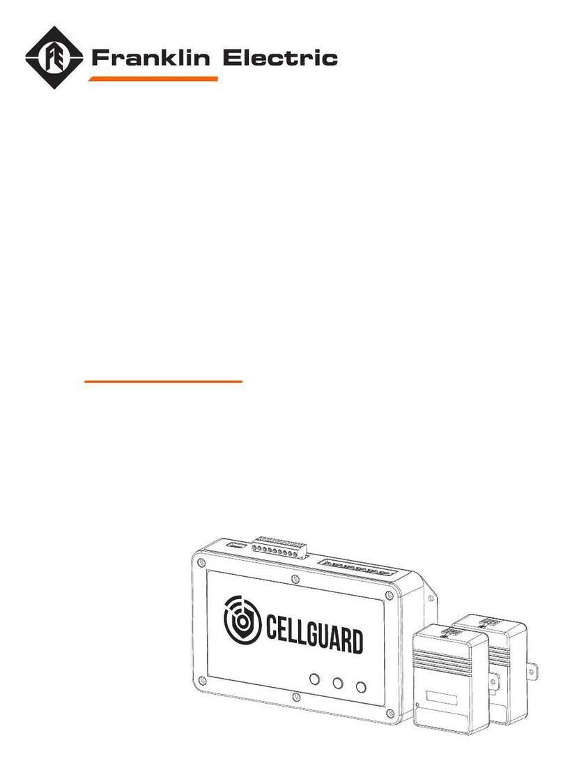
Franklin Electric CELLGUARD CGBC WD Series User manual

FUELING SYSTEMS
GRID SOLUTIONS
EV SYSTEMS
CELLGUARD™
WIRED BATTERY MONITORING SYSTEM
INSTALL GUIDE
167-000800 r2
CONTROL MODULES
CGBC-XXX-WD
STRING SENSOR MODULES
CGTC3-600-WD
BATTERY SENSOR MODULES &
ADDRESS MODIFIERS
CGS3-XXX-WD
CGS3-XX-WD
BATTERY HARNESSES &
INTERCONNECT CABLES
CGS3-XXBH-WD
CGS3-XXCBL-WD
CGS3-XXXCBL-WD
CGS3-XXXX-WD

The information in this publication is provided for reference only. While every eort has been made to ensure the reliability and accuracy of the information contained in
this document at the time of printing, we recommend that you refer to the appropriate website for the most current version of this manual. All product specifications, as
well as the information contained in this publication, are subject to change without notice. Franklin Electric does not assume responsibility and expressly disclaims liability
for loss, damage, or expense arising out of, or in any way connected with, installation, operation, use, or maintenance by using this document. Franklin Electric assumes
no responsibility for any infringement of patents or other rights of third parties that may result from use of this document or the products. We make no warranty of any kind
with regard to this material, including, but not limited to, the implied warranties of merchantability and fitness for a particular purpose.
Copyright © 2023 Franklin Electric Co., Inc., Madison, WI 53718. All world rights reserved. No part of this publication may be stored in a retrieval system, transmitted, or
reproduced in any way, including, but not limited to, photocopy, photograph, magnetic, or other record, without the prior written permission of Franklin Electric.
For technical support, please contact:
Franklin Electric Technical Support
Web: franklinfueling.freshdesk.com/support/home
Tel: +1 800 984 6266
For additional questions and concerns, please contact:
Franklin Electric
3760 Marsh Rd
Madison, WI 53718 USA
Web: franklingrid.com
Tel: USA & Canada +1 800 225 9787 • Tel: UK +44 (0) 1473 243300
Tel: Mex 001 800 738 7610 • Tel: DE +49 6571 105 380 • Tel: CN +86 10 8565 4566
CELLTRAQ is registered trademark of Franklin Electric Co., Inc.
167-000800 r2
CONVENTIONS USED IN THIS MANUAL
This manual includes safety precautions and other important information presented in the following format:
NOTE: This provides helpful supplementary information.
IMPORTANT: This provides important supplementary information and instructions to avoid damaging hardware or a potential hazard.
CAUTION: This indicates a potentially hazardous situation that could result in minor or moderate injury if not avoided. This may also be used to alert against
unsafe practices.
WARNING: This indicates a potentially hazardous situation that could result in severe injury or death if not avoided.
DANGER: This indicates an imminently hazardous situation that will result in death if not avoided.
OPERATING PRECAUTIONS
WARNING: Important safety instructions. Before installing any Franklin Electric equipment, read this document and follow safety and operating instructions.
Save these instructions.
WARNING: Risk of explosive gases: Batteries generate explosive gases during normal operation, and when discharged or charged.
WARNING: To reduce risk of battery explosion, follow these safety instructions and those published by the battery manufacturer and the manufacturer of any
equipment to be used in the vicinity of a battery. Review cautionary marking on these products and on the battery cabinets, battery racks, battery rooms, and on
equipment containing the battery.
WARNING: Do not disassemble any equipment; contact Franklin Electric when a repair is required. Incorrect reassembly may result in a risk of electric shock, fire or
other hazardous situation.
WARNING: Use Franklin Electric equipment in dry, well-ventilated area(s).
WARNING: Do not expose Franklin Electric equipment to rain, snow, or other moisture.
WARNING: To avoid electric shock when testing jars, abide by your company’s safety practices and the following guidelines:
WARNING: Service work may only be performed by authorized personnel for procedures which they have satisfactorily been trained to execute.
WARNING: Refer to NFPA 70E for electrical safety requirements.
WARNING: Use of Personal Protection Equipment (PPE) and Protective Clothing per NFPA 70E guidelines is required. Some examples of these (but not limited
to) are: Electrical-insulating, acid-resistant, and protective gloves and sleeves per ASTM D 120, OSHA 29 CFR 1910.137, and NFPA 70E requirements; Protective
footwear; Aprons (acid-resistant); Insulating blankets; On-site spill kits; Protective clothing for voltage levels, level of corrosive protection, and the amount of arc-flash
protection provided; Insulated rescue hooks or other means for pulling personnel from live circuits; Eyewash stations or portable eyewash bottles; Class “C” dry chemical
re-extinguishers instead of water around battery systems.
WARNING: Always have someone within vocal range, or close enough to come to aid, when working around lead acid batteries.
WARNING: Have plenty of fresh water and baking soda nearby in case battery acid contacts skin, clothing or eyes.
WARNING: If battery acid contacts skin or clothing, wash immediately with baking soda and water. If acid enters the eye, immediately flush with cold running water for
at least 10 – 15 minutes, and seek medical attention.
WARNING: Never smoke or allow a spark or flame in the vicinity of a battery or engine.
WARNING: Be extra cautious to reduce the risk of dropping a metal tool onto the battery or other component, potentially causing a spark, short circuit or other
electrical part to possibly explode.
WARNING: Before working with a lead-acid battery, remove personal metal items such as rings, bracelets, necklaces, watches, etc. A lead-acid battery can produce a
short circuit current high enough to weld such items causing a severe burn.
WARNING: Always wear safety glasses with side shields in the vicinity of battery work per 29CFR1910.133 (OSHA).
WARNING: Do not disconnect the battery cables from power systems during the test without authorization.
WARNING: Do not place yourself in an electrical circuit.
WARNING: Avoid simultaneous contact with the jar and with the battery cabinet, racks, or hardware that may be grounded.
WARNING: Battery posts, terminals, and related accessories contain lead and lead compounds, chemicals known to cause cancer and birth defects or other
reproductive harm. Wash hands after handling.

Contents
1 Introduction.......................................................................................................................5
1.1 Documentation..........................................................................................................5
1.1.1 Symbol Legend ...............................................................................................5
2 Safety/Security ..................................................................................................................6
2.1 General Safety Information.........................................................................................6
2.2 Hazard Assessment ...................................................................................................6
2.3 Required Personal Protective Equipment (PPEs) ........................................................7
2.4 Cyber Security ...........................................................................................................7
3 Technical Overview ............................................................................................................8
3.1 System Components..................................................................................................8
3.1.1 Base Controller Module (BCM) ........................................................................9
3.1.2 Battery (TA) Sensors .....................................................................................10
3.1.3 String (TC) Sensors .......................................................................................10
3.2 Accessories .............................................................................................................11
3.3 Dimensions & Identification .....................................................................................12
3.3.1 Base Controller Module (BCM) ......................................................................12
3.3.2 Battery Sensor Components (TA)...................................................................13
3.3.3 String Sensor Components (TC).....................................................................13
4 Installation.......................................................................................................................14
4.1 Pre-Installation Inspection .......................................................................................14
4.2 Required Tools.........................................................................................................14
4.3 Install Instructions ...................................................................................................15
4.3.1 Numbering Batteries.....................................................................................15
4.3.2 Sensor Installation ........................................................................................16
4.3.2.1 Installing Sensor Cables .................................................................17
4.3.2.2 Crimping Sensor Cables .................................................................17
4.3.2.3 Addressing Sensors........................................................................18
4.3.2.4 Addressing TCs ..............................................................................18
4.3.2.5 Connecting The BCM & TC .............................................................19
4.3.3 Wiring TAs.....................................................................................................20
4.3.3.1 Wiring Multiple String Sensors (Series) ...........................................21
4.3.3.2 Wiring Multiple String Sensors (Parallel) .........................................21
4.3.4 Wiring The BCM & TC....................................................................................21
4.3.5 Connecting The Current Transducer ..............................................................22
4.3.6 Powering The BCM........................................................................................23

4
4.3.7 Commissioning The BCM ..............................................................................23
4.3.7.1 Connecting The BCM Web Interface ...............................................23
4.3.7.2 Using The Integrator Tool................................................................24
4.3.7.2.1 Setting Up String Parameters........................................24
4.3.7.2.2 Changing Port Settings .................................................25
4.3.7.2.3 Changing IR Settings ....................................................26
4.3.7.2.4 Connecting The BCM Web Interface..............................26
4.3.7.2.5 Configuring Network Connections.................................27
4.3.7.2.6 Performing The Resistance Test ....................................28
4.3.7.2.7 Configuring The Franklin Interface ................................29
4.3.7.2.8 Starting The Franklin Interface (FI)................................30
4.3.7.3 Commissioning The Site .................................................................31
4.3.7.4 Setting Up Batteries .......................................................................32
4.3.7.5 Setting Alert Limits.........................................................................34
4.3.7.5.1 Setting Discharge Limits ...............................................35
4.3.7.6 Testing & Confirming Communication.............................................35
4.3.7.7 Editing IP Address Names ..............................................................36
5 Appendix.........................................................................................................................37
5.1 Related Documents .................................................................................................37
5.2 Glossary ..................................................................................................................37

5
1 Introduction
The CELLGUARD™ Wired Battery Monitoring System (BMS) delivers economical,
yet highly accurate and reliable remote health analysis of stationary batteries in
applications with high electromagnetic noise.
1.1 Documentation
• This document is intended for qualified and certified installation persons.
• Instructions of this document are in English. All other language versions are
translations of this original document.
• Illustrations in this document show a typical setup and are for instruction and
description purposes only.
• The information given in this document is given as a guide only. It is the
installer's responsibility to ensure that correct and safe procedures are followed.
1.1.1 Symbol Legend
Wear Protective Headwear Wear Eye Protection
Wear Protective Clothing Wear High-Visibility Clothing
Wear Protective Gloves Wear Safety Footwear
Refer to instruction guide. Connect an earth terminal to the ground
Disconnect main plug from electrical outlet.
Disconnect before carrying out maintenance or repair.
Warning: Electricity General Warning
Warning: Flammable Material
No open flame; Fire, open ignition source and smoking prohibited

6
2 Safety/Security
2.1 General Safety Information
• Only perform procedures in this document that you are qualified and certified to perform.
• Personnel working on or with energized equipment must be authorized by
relevant regulatory bodies to carry out such work and must have the appropriate
training. Check with your employer and relevant regulatory body’s rules for
working with energized equipment.
• Obey all local laws, rules, regulations, and instructions in this document. In
case of inconsistency or contradiction between information contained in this
document and any laws, rules and regulations, obey the stricter of the two.
• Keep unqualified personnel at a safe distance during installation.
• Always wear all required PPE on-site and during installation.
• If it is necessary to remove safety/security devices, immediately reinstall the
safety / security devices after completing the work.
2.2 Hazard Assessment
Prior to beginning work and prior to recommencing work after leaving and returning
to the worksite, a worksite, pre-job hazard assessment must be performed to identify
safety and environmental needs. At a minimum, this hazard assessment should:
• Identify possible hazards and risks.
• Identify the safety needs of the job.
• Identify the correct procedures, practices and equipment.
• Eliminate unsafe conditions and actions from the worksite.
• Identify the need for personal protective equipment.
• Inspect equipment before use.
• Confirm sheaths of all cables are secured and undamaged.
• Confirm plugs and connectors are properly connected and serviceable.
• Perform ongoing risk assessment during the project.

7
2.3 Required Personal Protective Equipment (PPEs)
These PPEs are required during all phases of installation.
Wear Protective Clothing Wear Eye Protection
Wear High-Visibility Clothing Wear Protective Gloves
Wear Protective Headwear Wear Safety Footwear
2.4 Cyber Security
This product is designed to be connected to and to communicate information and
data via a network interface. It is solely the owner’s responsibility to provide and
continuously ensure a secure connection between the product and Owner’s network
or any other network (as the case may be).
The Owner shall establish and maintain appropriate measures (such as but not limited
to the installation of firewalls, application of authentication measures, encryption of
data, installation of anti-virus programs, etc.) to protect the product, the network, its
system and the interface against any kind of security breaches, unauthorized access,
interference, intrusion, leakage and/or theft of data or information.
The manufacturer. Franklin Electric, and its aliates are not liable for damages and/ or
losses related to such security breaches, unauthorized access, interference, intrusion,
leakage and / or theft of data or information.

8
3 Technical Overview
3.1 System Components
1. Base Controller Module (BCM)
2. Battery Sensor Module (TA)
3. String Sensor Module (TC)
4. Current Transducer
5. CELLTRAQ™ data management software
Standard Configuration
• Allows online monitoring of cell voltage, internal resistance, temperature, string
voltage, charge / discharge current, and ambient temperature.
• Provides automatic over-limit alarms.
• Provides data storage functions and can upload data though an RS-485 or
network port.
• Has one dry-contact output.

9
3.1.1 Base Controller Module (BCM)
The BCM
• Is connected through either an
Ethernet (RJ-45) or a serial port
(RS-485) providing centralized
management and the ability to
view the health of battery string.*
• Can read monitoring values
one-by-one providing analysis and
processing of data received from
TAs and TCs.
• Has a maximum of six battery strings for each BCM and two strings per COM port.
• Uses Integrator software to configure the BCM during installation
• Sensors are connected through a UART bus, back to the BCM.
NOTE: *Monitoring software and middleware are required for viewing data.
Specific Functions
The BCM reads each sensor in series to the end strings or strings including a TC.
• Parameters for string(s) set up in the Integrator software, cover upper and lower
alarm limits.
• An automatic alarm function (when an alarm occurs, the E2 light illuminates).
• The LAN port is an Ethernet RJ45.
• The Upload port is Serial RS-485 (COM4).”
• “The COM ports are RJ22 (COM1–COM3).
• Power Options:
• CGBC-300-WD (BCM) 85 to 246 VAC / 110 VDC to 370 VDC, 10 W.
• CGBC-300-WD-48V (BCM) 36 to 72 VDC (DC ONLY), 15 W.

10
3.1.2 Battery (TA) Sensors
• Monitor voltage, internal resistance and temperature of each cell, uploading the
data through the COM port.
• Are powered by the monitored battery.
• 1 V Ni-Cd, 13 mA maximum.
• 6 V, less than 7 mA.
• 2 V current absorption, 7 mA maximum
(no more than 13 mA).
• 12 V current absorption, 3 mA maximum
(no more the 7 mA).
• Must be installed on a battery with the
appropriate voltage for the sensor or the unit
can be damaged:
• 1 V Ni-Cd only.
• 6 V battery only.
• 2 V battery only.
• 12 V battery only.
3.1.3 String (TC) Sensors
• Monitor ambient temperature and the charge / discharge current for one
battery string.
• Require separate TCs for each battery string.
• Communicates with the BCM through the COM1 and COM2 serial ports.
• The current threshold is -3 Amp with a sample rate every 20 seconds.

11
3.2 Accessories
• Battery tabs (acquisition terminal).
• The Address Modifier, p/n CGS3-AMM-WD is used to address TAs and TCs.
• The Interconnect cable is used to connect TAs and TCs to the BCM and is
included with sensors. Cables are available in 30, 70, 100 and 800 cm lengths.
• The Sensor-Battery cable is included with sensors. The cable is available in
25, 50 and 80 cm lengths..

12
3.3 Dimensions & Identification
3.3.1 Base Controller Module (BCM)
1. Alarm indicator lights
2. Power input
3. Power output
4. Dry contact
5. Upload port (COM4)
6. LAN port
7. Communication ports (COM1–COM3)
Indicator Lights
P – Power light
A – Alarm light
E1 – Communication failure
E2 – Battery alarm
R1 / T1 – Transmit and receive for COM1
R2 / T2 – Transmit and receive for COM2
R3 / T3 – Transmit and receive for COM3
R4 / T4 – Transmit and receive for COM4

13
3.3.2 Battery Sensor Components (TA)
1. Indicator light
2. Battery connection port
3. COM port (COM1–COM2)
3.3.3 String Sensor Components (TC)
1. Indicator light
2. Current transducer connection port
3. COM port (COM1–COM2)
4. Power input

14
4 Installation
NOTE: When the installation is complete, leave this guide for the owner or operator.
4.1 Pre-Installation Inspection
Upon Receipt of Item(s)
• Verify all items are in accordance with the order.
• Check all items for damage.
• If any item shows damage or is not in accordance with the order, inform
Franklin Electric immediately.
• Remove the packaging material.
• Follow all local laws, rules and regulations regarding disposal of discarded
parts, packaging material or items and any subsequent components.
4.2 Required Tools
NOTE: Tools listed here should be insulated for use around electricity and rated for the
energy level to which they may be exposed.
Permanent Marker
RJ-22

15
4.3 Install Instructions
4.3.1 Numbering Batteries
Before connecting the TAs to the batteries, label and number both the TAs and
batteries clearly.
Battery String
1 2 3 n n n
+ +
1 2
• The first battery, or battery NO.1, must be the first one on the string's most
positive terminal, the NO.2 is the battery following the NO.1 battery, and so on:
• Multiple strings with separate ports and sensors in parallel:
• Each string starts with 1 and continues to the last battery in the string.
• Each string requires a TC.
• Example: 120 Batteries consisting of two strings of 60:
• String 1: 1–60 (addressing).
• String 2: 1–60 (addressing).
• Multiple strings that use the same port (maximum two strings) with sensors
in series:
• String 1: 1–30 (addressing).
• String 2: 31–60 (addressing).
• Second TC (has an address dierent from the first TC).
• The last battery is the one attached closest to the string most negative terminal.
Number the batteries according to this practice.
NOTE: The BMS is a multiple string system. COM ports 1–3 on the BCM are capable of
supporting two strings for each COM port (six strings maximum).

16
4.3.2 Sensor Installation
Install the U-type acquisition terminals (provided) on each post on top of the batteries
to be monitored. Install the terminals in the following order:
• U-type acquisition terminals > Flat washer > Spring washer > Nut (or bolt).
Battery Connector
U-type Acquisition Terminal
Flat Washer
Spring Lock Washer
Hex Nut

17
4.3.2.1 Installing Sensor Cables
Attach the appropriate end of the sensor cable to the tabs on the U-type acquisition
terminal, and then plug the sensor cable into the sensor module connector.
4.3.2.2 Crimping Sensor Cables
IMPORTANT: You must use an RJ-22 crimping tool.

18
4.3.2.3 Addressing Sensors
1. Make sure the sensors are secured on the
batteries, and confirm the power light in
the lower left corner is green.
2. To use the TA address modifier (provided):
• Connect the connector wire to the TA
address modifier and COM1 of the
sensor.
• Press the up or down arrow at the
bottom of the TA address modifier
until the desired address number
appears on the TA address modifier
display (1–240).
• Press Enter (the Active light flashes
green).
• After the address is changed, the TA
address modifier changes to the next
address automatically.
• Connect the TA address modifier to the next sensor, and press Enter until
the entire string is addressed.
IMPORTANT: Sensors will not address if the cable is connected to COM2. Make sure
only the TA address modifier is connected to the sensor when you attempt to the
address the sensor.
4.3.2.4 Addressing TCs
The default TC address is 241, but you can choose an address from 241–247. If you
are monitoring only one battery string, the address can remain the default.
To change the address:
1. Connect the address modifier to COM1 on the TC.
2. Turn on the address modifier power switch.
3. Press the ESC button.
4. Use the arrow buttons to change the address.
5. Press Enter to select the next digit. After you set the last digit,
press Enter.
6. Press the arrow to select H-C, and then press Enter.
7. When “96” appears in the address modifier display, press
Enter. The address will appear in the display.
8. Press Enter. When the ACTIVE light turns green, the change
is complete.
Power Light
COM1

19
4.3.2.5 Connecting The BCM & TC
The BCM
• COM1 on the BCM:
• Left side to either COM port on the TC.
• Right side from COM2 of the last battery in string 1 or string 2, if using two
strings for each COM port.
The TC
• COM1 and COM2 operate identically once the TC is addressed.

20
4.3.3 Wiring TAs
TA 1
• COM1 and COM2 act identically once they are addressed.
• The last sensor in the string, COM2, has a home run back to the right port on
COM1 on the BCM.
BC
TC
Last sensor in string
This manual suits for next models
4
Table of contents
Other Franklin Electric Measuring Instrument manuals

Franklin Electric
Franklin Electric CELLTRON ADVANTAGE DIGITAL User manual

Franklin Electric
Franklin Electric CELLGUARD GEN III User manual

Franklin Electric
Franklin Electric CELLGUARD CGBC-350-HWD User manual

Franklin Electric
Franklin Electric INCON DTM-4 User manual

Franklin Electric
Franklin Electric Little Giant CONDALERT LC-110 User manual