Fraser IONFIX COMPACT User manual

IONFIXPRO
STATICGENERATORWITHREMOTE
MONITORINGANDCONTROLINTERFACE
QUICKSTARTGUIDE


3© Fraser Anti-Static Techniques Ltd 2017
Page
Safety 2
Introduction 3
Installation 3
CommissioningandOperation 4
RemoteInterface 4
TechnicalSpecifications 6
Troubleshooting 7
TheFraserIONFIXPROhasbeendesignedinaccordancewiththesafetyrequirementsof
EN62368-1:2014.
Thehigh-voltageoutputofthegeneratorisaClass2electricalenergysource,asdefinedin
EN623681:2014.Thismeansthatitiscapableofcausingpainifcontactismadewithabodypart,butis
notlikelytocauseaninjuryrequiringmedicalattention.
Ifthegeneratoristobeoperatedbyordinarypersons,itmustbeinstalledinsuchamannerthatthehigh
voltageoutputconnectorsarenotaccessibleinnormaloperation,forexamplebymountingwithinan
enclosureorprovidingappropriateguards.
Forfurtherdetails,seethefullgeneratormanual.
Explanation of Symbols
Throughoutthismanualthefollowingsymbolsareusedtodrawattentiontoimportantinformation.
Warning:Thissymbolreferstooperationswhich,ifcarriedoutimproperly, mayresultin
seriouspersonalinjuriesordamagetoproperty.
Information:Thissymbolreferstoinformationwhichrelatestoobtainingthebest
performanceandoperatinglifefromtheproduct.
Safety
Contents

4
IONFIX_PROGEN_QuickGuide_Iss.1
Thismanualprovidesa brief installation and commissioning guide for the FraserIONFIX PROStatic
Generatorproduct range(30and60kVvariants).Pleaserefertothefullmanualforinformationonall
functionsofthegeneratorand detailed instructions for remote interfacing and machinery integration.
Installation
• Installationmustonlybecarriedoutbysuitably qualified personnel.
• Thegeneratormust be earthed via both the power cable and externalearthwire.
• Disconnectthemainspowercablebeforestartinganywork on the generator.
• Connectonlyapprovedchargingelectrodestothegenerator.
• Donottouchthechargingelectrode(s)whenenergised.
• Refertothefullmanualfordetailedinstallationinstructions.
1. Ensurethatthegeneratoris correctly earthed as described above.
2. Securelymountthegeneratorin a visible, accessible and stable location using the supplied
mountingbracketsifnecessary.Ensurethatthelocationiscleananddry.
3. Connectthechargingelectrode(s)totheHVoutputsocketsattherearofthegenerator.The4
socketsareconnectedtogetherinternally.
• DonotrouteHVcablesneartosharpmetalcomponents.
• AvoidbendsorkinksintheHVcables.
• RouteHVcablesseparatelyfrom low-voltagecables.
• KeepHV cables as short as practicallypossible.
4. Ifusingtheremoteinterface,connectthecabletotheD-typeconnector.Fordetails, see ‘Remote
Interface’sectionofthefullgeneratormanual.
5. Connectthepowercabletothegeneratorand connect it to the mains supply.
Introduction

5©FraserAnti-StaticTechniquesLtd2017
Generator Controls
Onthefrontofthegeneratorthere is a power switch, a displayscreen,controlbuttonsandstatus
indicatorsasshownbelow.
• Display: Indicatesthe settings and output parametersofthegenerator, displaysthegenerator
configurationmenu and anywarningmessages.
• ‘HV’ indicator: Illuminates when the HV output is enabled.
• ‘Remote’ indicator: Illuminateswhenanyof the remote control functions are enabled.
• ‘Current Limited’ indicator: Illuminateswhen the output current reaches the limit value.
• RUN/STOP Button: Togglesthe high voltageoutputofthegeneratoronandoff.
• Voltage +/- Buttons: Allowthehighvoltageoutputlevelof the generatortobeadjusted.
• Current Limit +/- Buttons: Allowtheoutputcurrentlimitlevelofthegeneratortobeadjusted.
• 4-way keypad and OK Button: Usedto access the generatorconfigurationmenuandchange
parameters.
Controls and Operation

6
IONFIX_PROGEN_QuickGuide_Iss.1
Operating the generator
Powerup the generator,using the main power switch.
Afterastart-upmessage,thescreenwillshowthevoltageand current setpoint values (indicated by‘SP’
afterthevalues).
• Toadjusttheoutputvoltage,use the ‘Voltage+’ and ‘Voltage–‘buttons.
• Toadjustthecurrentlimit,usethe‘Current–’and ‘Current+’.
• Toturnonoroffthehighvoltageoutput of the generatorpressthe‘RUN/STOP’button.
Whenthehighvoltageis enabled, ‘OP’willbeshownaftertheactualoutputvaluesonthescreen.
Commissioning
Thefollowingisabriefguidetosettingupthegeneratorfor use as a continuous charging source.
Whendelivered,the output voltagesetpointwillbesettozero,andthecurrentlimitsettoitsmaximum
value.
• EnabletheHVoutput(press‘RUN/STOP’)andincreasetheoutputvoltageuntilthedesired
pinningeffectisachieved.Increasethevoltagebyaround 10% abovethistoaccommodate
processandmaterialvariations. Takeanoteofthecurrentdrawn.
• Tominimiseelectrodewearwhenthematerialisnotpresent,reducethecurrentlimitsetting
toabout10%abovethecurrentdrawnin operationensuringthatthe‘currentlimited’indicator
doesnotilluminatewhenthematerialispresent.
BydefaulttheHighVoltageOutput is off when the generatorispoweredup.Ifitisnecessarytohavethe
HVcomeonatpower-up,thiscanbeachievedusingtheremoteinterface.Seefullmanualfordetails.

7©FraserAnti-StaticTechniquesLtd2017
Generator conguration menu
Thegeneratorconfigurationmenuhasfoursections:
1. Remote Mode –allowsthegeneratorremote interface to be enabled and configured.
2. Advanced Settings –allowsvariousaspectsofgeneratoroperationtobeadjusted.
3. System Information –providesdiagnosticinformationaboutthegenerator.
4. Fault Count -providesdiagnostic information about the generator.
Seethefullmanualfordetailsoftheconfigurationmenu and settings/parameters.
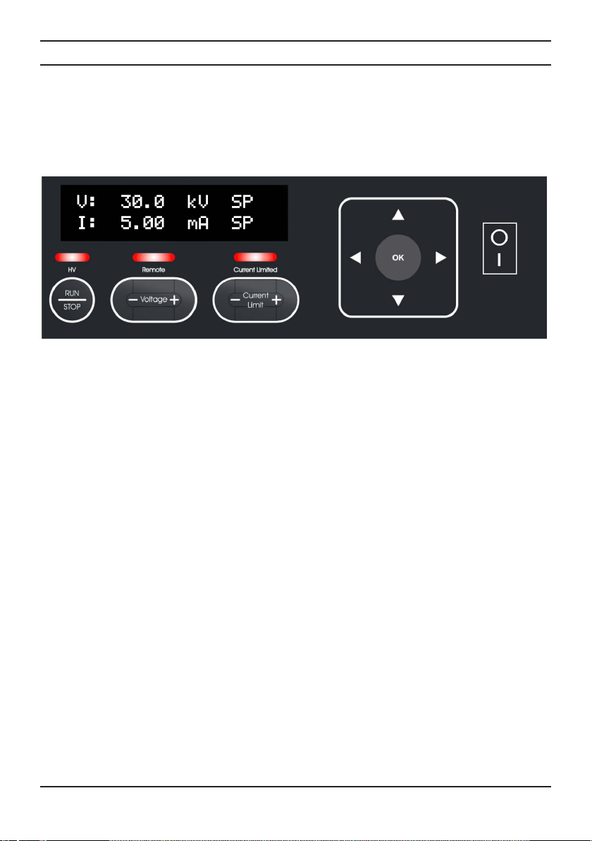
Toaccessthemenuthefollowingkeysareused:
• Right (►): Entermenusystem,movedowntoalowerlevel,accessparametertoadjust.
• Left (◄):Moveuptoahighermenulevel,exitmenu system.
• Up (▲):Moveupalistofmenuitems,increaseparametervalue.
• Down (▼): Movedownalistofmenuitems,decreaseparametervalue.
• OK: Movedowntoalowermenulevel,saveparametersetting.
Pressinganyof the setpoint adjustment buttons (Voltage+/-,Current +/-)whilstusingthemenuwillexit
themenusystem.
Remote Interface
Thegeneratoris equipped with a remote control and monitoring interface, providedona25-wayD-type
socketattherearofthegenerator.Thefunctionsandconnectionsareasfollows:
Pin No. Function Pin No. Function
1 Remoteon/offinput +ve 14 Remoteon/offinput -ve
2 Remotecurrentsetpointinput 15 GND(0V)
3 Remotevoltagesetpoint input 16 GND (0 V)
4 Remotevoltagemonitor output 17 GND (0 V)
5 Remotecurrentmonitorouput 18 Reserved,do not connect
6 Reserved,do not connect 19 GND(0V)
7 +12Vreferenceoutput 20 GND(0V)
8 Reserved,do not connect 21 Reserved,do not connect
9 Arc/Limitopencollector 22 Arc/Limitopen emitter
10 Operatingopen collector 23 Operatingopen emitter
11 Reserved,do not connect 24 GND(0V)
12 Notconnected 25 Reserved,do not connect
13 Notconnected

8
IONFIX_PROGEN_QuickGuide_Iss.1
Technical Specications
Electrical Characteristics
Input rating: 90–250VAC,47 – 63 Hz, 3 A max.
Input connector: IEC60320C14inlet.
Output rating, 30 kV variants: 0-30kVDC,5mAmax.
Output rating, 60 kV variants: 0-60kVDC,2.5mAmax.
Output connector type: 4xFraser30/60kVtubularspring-contactHVconnector.
Remote interface connector: 25-pinsubminiatureD-type,female.
MatingplugAmphenolL717DB25Porequivalent.
Environmental Conditions
Ambient temperature: 0–50°C
Relative humidity: Maximum70%,non-condensing.
Ingress protection: IP20.
Mechanical
Dimensions (D x W x H): 337mmx268mmx104mm
Weight: 8kg

9© Fraser Anti-Static Techniques Ltd 2017
Troubleshooting
Incaseofproblemswiththegenerator, consult the following table to aid diagnosis and remedy.
Problem Cause Remedy
Nooutputvoltage
Displayoff
Powersupply not connected or
energised. Checkpowersupplyconnections.
ACvariant: inlet fuse blown. Replace fuse.
Hardwarefault. Contactdistributor.
Nooutputvoltage
Displayon
Voltagesetpoint not changed
fromdefault0.0kVorremote
setpointnotprovided.
ChangesetpointusingVoltage+/-
buttonsorprovide0-10 V signal on
remoteinterface.
Remoteon/offenabled, but no
remoteon/offsignal provided. Provideremoteon/offsignal.
Currentlimitsettoolow. IncreasecurrentlimitusingCurrent
+/-buttons.
AllLEDsflashing
‘OVERLOAD’shownon
display
Arcingorshort-circuitonHV
outputduetoelectrodeorcable
fault.
Checkandrectifyelectrodeorcable
faults.
Generatoroverloaded. Movechargingelectrode(s)further
fromcounter-electrode.
AllLEDsflashing
‘OVERTEMP’shownon
display
Generatorinternal temperature
toohigh. Movegeneratortocoolerlocation.
Reduceloadingongenerator.
AllLEDsflashing
‘UNDERVOLTAGE’shown
ondisplay Supplyvoltagetoolow. Checksupply voltage.
AllLEDsflashing
‘OVERVOLTAGE’shown
ondisplay Supplyvoltagetoohigh. Checksupplyvoltage.
AllLEDsflashing
Anyother message shown
ondisplay Internalfault with generator. Contactdistributor.


ScottsBusinessPark,Bampton, Devon,GB,EX169DN
T+44(0)1398331114F+44(0)1398331411
E[email protected]W www.fraser-antistatic.com
Formoreinformationaboutstaticandtoviewthefullrange
ofourproducts,pleasevisitwww.fraser-antistatic.com
Other manuals for IONFIX COMPACT
1
Table of contents
Other Fraser Power Supply manuals
Popular Power Supply manuals by other brands

Moxa Technologies
Moxa Technologies DR-120 Series Hardware installation guide

Vimar
Vimar ELVOX 6837 instruction manual

Pulsar
Pulsar PSU-B-13,8V/S-5A/1/EL-TR-17Ah/MC quick start guide

Elektro-Automatik
Elektro-Automatik PS 800 R Series user guide

Allen-Bradley
Allen-Bradley 1606-XLE480FP installation instructions

Fire-Lite Alarms
Fire-Lite Alarms APS-6RF installation instructions