FS15-60-120 Rev0204
2
CONTENTS Table of Contents
CONTENTS ............................................................................................................... 2
List of Tables ......................................................................................................... 2
List of Figures ....................................................................................................... 2
INTRODUCTION ...................................................................................................... 3
Overview ............................................................................................................... 3
Features ................................................................................................................. 3
Specifications ........................................................................................................ 4
GENERAL DESCRIPTION....................................................................................... 6
Components........................................................................................................... 6
Controls and Indicators ......................................................................................... 8
INSTALLATION......................................................................................................10
Install Control Module ........................................................................................ 10
Install Metering Valve Assembly and Eductor....................................................10
Install Flow Sensor(s) ......................................................................................... 12
Install Summing Device ......................................................................................18
Install Cables ....................................................................................................... 18
THEORY OF OPERATION ..................................................................................... 20
OPERATION ............................................................................................................22
Static Operational Check.....................................................................................22
Pump Intake and Discharge Pressure Requirements...........................................23
Operational Check............................................................................................... 24
CALIBRATION........................................................................................................ 28
TROUBLESHOOTING TIPS .................................................................................. 30
MAINTENANCE.....................................................................................................31
Flushing the System ............................................................................................31
Cleaning the Paddlewheel Sensors ..................................................................... 31
List of Tables
Table 1. Pump Pressure Requirements ....................................................................23
List of Figures
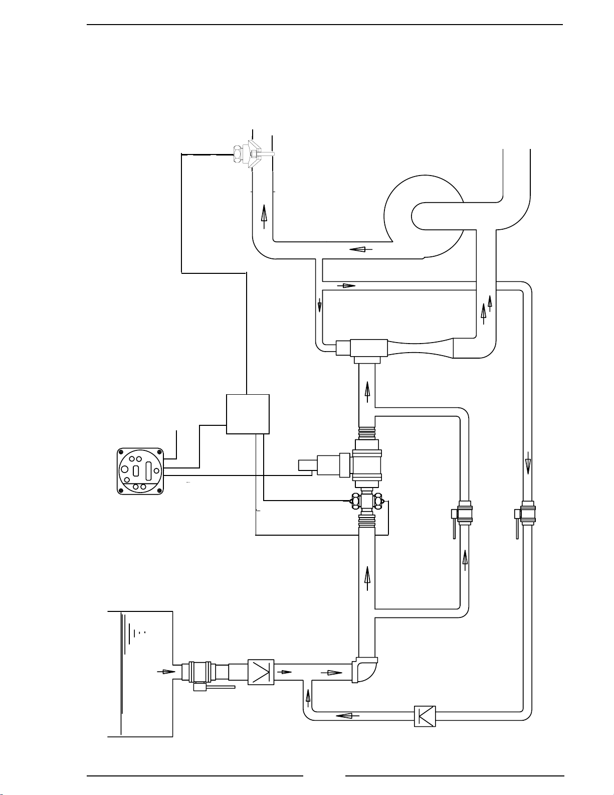
Figure 1. Plumbing Schematic ..................................................................................7
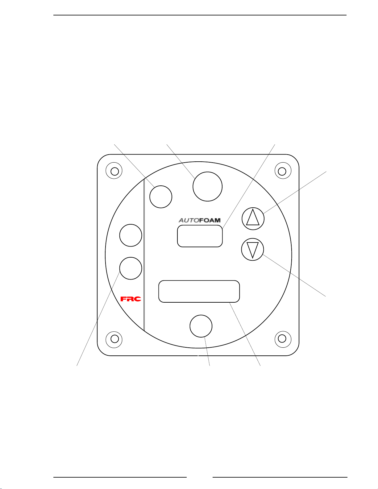
Figure 2. Controls and Indicators.............................................................................. 9
Figure 3. Control Module Dimensions ................................................................... 11
Figure 4. Meteing Valve Assembly and Eductor Installation ................................. 11
Figure 5. Flow Sensor Location Guidelines............................................................ 13
Figure 6. Saddle Clamp Installation........................................................................ 15
Figure 7. Weldment Installation ..............................................................................17
Figure 8. Cables....................................................................................................... 19
Figure 9. Sample Displays....................................................................................... 25
Figure 10. Summing Device.....................................................................................29
Figure 11. Drawings ................................................................................................. 32