FRC BRYTTE DAY Series User manual

OPA740 Rev1108
1
FIRE RESEARCH CORPORATION
www.fireresearch.com
26 Southern Blvd., Nesconset, NY11767
TEL ( 631 ) 724-8888 FAX ( 631 ) 360-9727 TOLL FREE 1-800-645-0074
BRYTTE DAY
PORTABLE LIGHTING
SYSTEM
MODELS: OPA740, OPA742,
OPA756, OPA769
Document Number:
XM-OPA74PM-R0A
HPA100
Power Pack
Standard with all
Brytte Day Systems
OPA742
Shown with optional
tripod carry handle.
OPA740
Matches the OPA700
Portable with a HPA100
Power Pack

OPA740 Rev1108
2
CONTENTS
Table of Contents
CONTENTS ................................................................................................................ 2
INTRODUCTION ...................................................................................................... 3
Overview ................................................................................................................ 3
Features .................................................................................................................. 3
Specifications ......................................................................................................... 4
SAFETY SUMMARY ................................................................................................ 6
CONTROLS AND INDICATORS ............................................................................. 7
ASSEMBLE ................................................................................................................ 8
Set Up .................................................................................................................... 8
Break Down ........................................................................................................... 8
OPERATION ............................................................................................................ 10
Emergency Back Up Mode ....................................................................................... 11
Power-Up ............................................................................................................. 12
Charge/Store Battery ............................................................................................ 13
MAINTENANCE ..................................................................................................... 14
Bulb Replacement ................................................................................................ 14
Cleaning ............................................................................................................... 14
List of Figures and Tables
Figure 1. Controls and Indicators ............................................................................... 7
Figure 2. Assemble ..................................................................................................... 9
Figure 3. Operation .................................................................................................. 10
Table 1. Battery Charge Levels ................................................................................. 12
Figure 4. Bulb Replacement .................................................................................... 15

OPA740 Rev1108
3
INTRODUCTION
Overview
The FRC BRYTTE DAY is a self contained high intensity Portable Scene Lighting
System that allows you to light a scene without the need for an on-site AC power
source. The BRYTTE DAY consists of an FRC Optimum HID lamphead, a telescopic
tripod, and a battery/charger unit that are all easily stored in a compartment or trunk
of a vehicle.
Features
Lamphead
The FRC Optimum lamphead contains a 70 or 150 watt HID (High Intensity
Discharge) bulb. The lamp head rotates 360 degrees and tilts both up and down. It has
a convenient carrying handle on top, a wire guard to protect the lamphead lens, and
comes with a vinyl carrying bag.
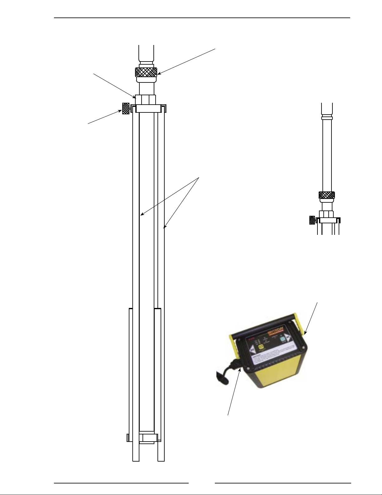
Telescopic Tripod
The tripod allows the lamphead to be extended up providing wide area coverage
by the lamphead. The tripod is designed to deploy all three legs at the same time,
allowing it to be set up quickly and easily at an incident. The telescopic pole includes
FRCs unique twist lock which makes raising and locking the telescopic pole in position
quick and easy. An internal brake lowers the pole slowly on a cushion of air. This helps
to prevent pinched fingers and damage to the bulb. An optional tripod carry handle is
available for OPA742 and OPA756 models.
Power Pack (HPA100)
The Power Pack battery/charger unit includes a 100% maintenance free sealed
AGM battery and a microprocessor controlled charger that are housed in a rugged
aluminum case. The battery unit powers the lamphead, and when fully charged
provides approximately 3 1/2 hours of scene lighting with a 70 watt HID bulb (1 3/4
hours with a 150 watt HID bulb). When plugged in to an AC outlet, the battery unit
provides continuous operation of the lamphead and simultaneously recharges the
battery. The battery/charger unit has an ON/OFF switch and LED, CHARGING and
DISCHARGING LEDs, CHECK CHARGE LEVEL switch with three LED level
indicators, built-in over-current and over temperature protection, and is available in
12 or 24 VDC models.
Emergency Back Up Mode
When programmed for the Emergency Back Up Mode the BrytteDay Power Pack
monitors the facility power via the AC charging cord. If AC power is lost the BrytteDay
light automatically comes on.

OPA740 Rev1108
4
Specifications
SCENE LIGHTING
Lamphead
Supply Voltage: 12 VDC
Bulb Type: 70 WATT HID, 6.0 AMPS, 5000 LUMENS
Bulb Type: 150 WATT HID, 12.5 AMPS, 11250 LUMENS
Supply Voltage: 24 VDC
Bulb Type: 70 WATT HID, 3.0 AMPS, 5000 LUMENS
Bulb Type: 150 WATT HID, 6.25 AMPS, 11250 LUMENS
Dimensions
Width: 9"
Depth: 9" (Including Wire Guard)
Height: 13"
Tripod
Material: Anodized Aluminum
Folded Lengths: OPA742 OPA756 OPA469
with Lamphead: 42 56 69
*w/o Lamphead: 32" 46" 59"
Extended Height: 62" 90" 115"
* Removable lamphead is optional.
Accessories
Removable Lamphead Option
Vinyl Carrying Bag for Lamphead (w/Removable Lamphead Option)
Tripod Carry Handle (OPA742 and OPA756 Only)
Safety Features
Wire Guard for Lamphead Lens
Air Brake Lowers the Telescopic Pole Slowly

OPA740 Rev1108
5
POWER PACK (Model HPA100 when ordered seperate)
Battery/Charger Unit
Battery Type: 33 Ah, Sealed AGM (Absorption Glass Mat)
* Must be ordered from the factory as a 12 or 24 volt model.
DC Connector: Marinco ConnectPro Twist Lock
Charger Supply Voltage: 88 to 132 VAC at 47 to 63 Hz
176 to 264 VAC (Option 240 VAC Unit)
Charger Supply Current: 3A at 120 VAC (2A at 240 VAC) Typical
Dimensions
Width: 11"
Depth: 6 1/2"
Height: 12"
Weight: 32.6 LBS (12V battery)
35.6 LBS (24V battey)
Accessories
AC Power/Charge Cord (Connector Options for 240 VAC Cord)
DC Charging Cord (12 VDC w/Cigarette Lighter Plug; 24 VDC w/pigtails)
Safety Features
Non-Spillable Battery
Built-in Over Current Protection
Built-in Over Temperature Protection
Battery/Charger Unit is Painted a Highly Visible Bright Yellow

OPA740 Rev1108
6
SAFETY SUMMARY
FRC lighting products are engineered and manufactured with safety in mind.
It is critical that FRC scene lights are maintained and operated correctly. Read and
understand all instructions before performing maintenance or operating.
The following safety precautions shall be observed while performing procedures
in thsi manual.
General Safety Precautions
Ensure power is off prior to connecting or disconnecting wires and plugs or
performing maintenance.
Lampheads are extremely hot when operating, do not use such that personnel or
equipment could inadvertently come in contact with the lamphead.
Operation Safety Precautions
Ensure that all lighting components are clear of obstructions when raising
telescopic poles.
Maintenance Safety Precautions
Refer to Maintenance section for procedures.
Ensure power is off prior to removing the front glass or opening covers.
Do not operate the light with the front glass removed or cover opened.
Ensure replacement bulbs have the same voltage and wattage.
When handling a new HID bulb avoid touching it except on the flat seal at either
end.
Use a clean soft cloth to wipe the reflector clean if necessary, do not use liquid
or aerosol cleaners.

OPA740 Rev1108
7
CONTROLS AND INDICATORS
DC Connector
Plug the power cord from the tripod or portable lamphead into this connector, also
used with DC charging cord.
CHECK CHARGE LEVEL and Level Indicating LEDs
When the button is pressed one of the three LEDs comes on to indicate the battery
charge level. No charging cords should be connected for the LEDs to give a correct
indication of the battery charge level. (Refer to Table 1. Battery Charge Levels.)
The three LEDs are used when the Emergency Back Up mode is activated and
when the battery is charging or in storage. (Refer to Operation Section.)
CHARGING/DISCHARGING LEDs
These LEDs indicate that the battery is charging or discharging. When the Power
Pack is connected to an AC power source, the CHARGING LED will be on.
OVERHEATING LED
Flashes to indicates an over heat condition.
ON/OFF Switch
This switch supplies DC voltage to the DC output connector. The green LED above
the switch indicates when the switch is on. Use this switch to turn the light on and off
and activate the Emergency Back Up mode. (Refer to Operation Section.)
AC Connector
Plug AC charging cord into this connector. The charging unit can charge the battery
and operate the light at the same time.
Figure 1. Controls and Indicators

OPA740 Rev1108
8
ASSEMBLE
Set Up
1. Hold the tripod near its top in a vertical orientation. Loosen the leg bracket
knurled knob allowing the three legs to be released. Lift the tripod and lower
the bracket to spread the legs (the wider the legs are spread, the more stable
the tripod will be).
2. Tighten the leg bracket knurled knob to lock the legs in place.
3. Removable Lamphead Only:
a. Remove the lamphead from the storage bag. Pull the pin and slip the lamphead
in the top of the telescopic pole. Insert the pin to hold the lamphead in place.
b. Connect the power cord to the lamphead.
4. Connect the power cord at the bottom of the tripod to the Power Pack DC
connnector.
5. If the Power Pack is to be connected to an AC source connect the AC cord,
the CHARGING LED comes on. (When the battery is trickle charging, the
CHARGING LED blinks.)
6. Adjust the lamphead angle then loosen the twist lock to raise the telescopic
pole. Tighten the twist lock to hold the pole in position.
Break Down
1. Press the ON/OFF button. The green LED and the DISCHARGING LED go
off. The light goes off.
2. If connected to an AC source the AC cord can be removed or left connected
to charge the battery.
3. Loosen the twist lock to lower the telescopic pole, the air brake helps lower
the pole slowly. Tighten the twist lock to hold pole in down position.
4. Disconnect the tripod power cord from the Power Pack DC connector.
5. Removable Lamphead Only:
a. Disconnect the power cord from the lamphead.
b. Pull the pin and slip the lamphead out of the telescopic pole. Place it in the
storage bag.
6. Loosen the leg bracket knurled knob and raise the bracket up to collapse the
legs. Tighten the leg bracket knurled knob to lock the legs in place.

OPA740 Rev1108
9
AC connector
for cord from AC
power source.
Lamphead
Not Shown
DC connector for
lamphead power cord.
Also used when
charging from a DC
power source
Twist Lock
Used to Raise and Lower Telescopic
Pole or Rotate the Lamphead
Leg Bracket
Knurled Knob
(Secures legs
in position.)
Leg
Bracket
Tripod
Legs
Telescopic Pole
Shown Raised
Figure 2. Assemble

OPA740 Rev1108
10
OPERATION
The 12 volt light operates under battery power for approximately two
hours with the 150 watt HID bulb when fully charged.
The light can be used for an extended period of time. Connect the Power
Pack to an AC power source. This provides for continuous use of the
light and recharges the battery at the same time. Not letting the battery
run down completely (light goes out) extends the life of the battery.
To ensure the battery is fully charged when needed it is recommended
that the Power Pack be stored plugged in to an AC or DC source in the
charge mode. This allows for a constant trickle charge. (When the battery
is trickle charging, the CHARGING LED blinks.)
Figure 3. Operation

OPA740 Rev1108
11
Emergency Back Up Mode
When programmed for the Emergency Back Up Mode the Power Pack monitors
the facility power via the AC charging cord. If AC power is lost the BrytteDay light
automatically comes on. When AC power is restored, the BrytteDay light goes off and
the Power Pack reverts back to monitor and charge mode.
1. Set up the BrytteDay and connect the AC power. (Refer to Assemble Section.).
The CHARGING LED comes on.
2. To set the emergency back up mode, press and hold the ON/OFF button until
the red LOW LED comes on. Release the ON/OFF button.
Results: The amber MED and green FULL LEDs alternately blink indicating
the emergency back up mode is activated.
In this mode the light operates normally:
Press the ON/OFF button, the green LED is on and the CHARGING LED is
on. The lamphead light comes on.
Press the ON/OFF button again, the green LED and the lamphead light go
off.
When AC power is lost:
The lamphead light automatically comes on. The CHARGING LED goes off
and the DISCHARGING LED comes on. The amber MED and green FULL
LEDs continue to alternately blink.
When AC power is restored:
The lamphead light automatically goes off. The DISCHARGING LED goes
off and the CHARGING LED comes on. The amber MED and green FULL
LEDs continue to alternately blink.
3. To exit the emergency back up mode, press and hold the ON/OFF button until
the red LOW LED comes on. Release the ON/OFF button.
Results: The amber MED and green FULL LEDs stop blinking indicating
the emergency back up mode is de-activated and the normal operating mode
resumes.

OPA740 Rev1108
12
Indicator Color 12 volt Battery Level 24 volt Battery Level
Green 12.45 to 12.8* volts 24.9 to 25.6* volts
Amber 12.06 to 12.45 volts 24.12 to 24.9 volts
Red Below 12.06 volts Below 214.12 volts
* Fully charged voltage level.
Table 1. Battery Charge Levels
This table is used when no charging cord is plugged in and
the CHECK CHARGE LEVEL button is pressed.
Power-Up
1. Set up the tripod and connect the cables. (Refer to Assemble Section.)
2. Press the ON/OFF button.
Result:The green LED is on and the DISCHARGING LED is on. The
lamphead light comes on. (If the Power Pack is connected to an AC source,
the CHARGING LED is on.)
3. Loosen the lamphead knurled knob to tilt the lamphead to desired angle.
4. Loosen the twist lock to extend the telescopic pole or rotate the lamphead,
tighten the twist lock to hold in position.
Checking the Charge Level:
Note: No charging cords should be connected for the LEDs to give a correct
indication of the battery charge level.
Press the CHECK CHARGE LEVEL button. One of the three LEDs comes
on to indicate the battery charge level
Refer to Table 1. Battery Charge Levels
Low Level Warning
When the light is operating from the battery and no charging cord is plugged in,
the red LOW LED blinks to warn that the battery power is getting low.
If the unit is stored and is not plugged in to trickle charge, the red LOW LED
blinks slowly to warn when the battery is at half charge.

OPA740 Rev1108
13
Charge/Store Battery
When depleated the battery should be charged for 11 hours to be fully charged.
To ensure the battery is fully charged when needed it is recommended that the
Power Pack be stored plugged in to an AC or DC source in the charge mode. This allows
for a constant trickle charge. When the battery is trickle charging, the CHARGING
LED blinks.
If the unit is stored and is not plugged in to trickle charge, the red LOW LED
blinks slowly to warn when the battery is at half charge.
AC Charging
Connect the AC charging cord to the Power Pack and plug it into an AC power
source. The CHARGING LED will come on to show the battery is charging. When
the battery is charged and switches over into trickle charging, the CHARGING LED
blinks.
The light can be connected and operated while the Power Pack is connected to an
AC source charging the battery.
When programmed for the Emergency Back Up Mode (refer to Operation Section.)
the Power Pack charges normally and monitors the facility power via the AC charging
cord. If AC power is lost the BrytteDay light automatically comes on. When AC power
is restored, the BrytteDay light goes off and the Power Pack reverts back to monitor
and charge mode.
DC Charging
With the vehicle running connect the DC charging cord to the Power Pack and
plug it into a cigarette lighter type receptacle. The CHARGING LED will come on to
show the Power Pack battery is charging. (The vehicle must be running to ensure the
charging voltage is high enough.)
The light can not be connected or operated while the Power Pack is charging from
a DC source.

OPA740 Rev1108
14
MAINTENANCE
Bulb Replacement
1. Ensure power is OFF and the lamphead is cool to the touch prior to replacing
the bulb.
2. Ensure the replacement bulb has the same voltage and wattage rating. (If there
are two bulbs installed, each bulb will be half the listed wattage.)
3. Remove the wire guard. Squeeze top to bottom and slip out of bezels.
4. Hold the glass in place while removing the bezels. Remove the four cap head
screws and remove the bezels. Remove the glass.
Note: Gasket is attached.
5. Slide the bulb sideways into the spring contact and lift it out from the opposite
side.
Note: When handling the new bulb avoid touching it except on the flat seal at
either end. (Grease or oily fingerprints can cause damage the quartz bulb.)
If the bulb is accidently touched, gently wipe it clean with alcohol.
6. Check both lamp base contacts to be sure they are perfectly clean.
7. Push one end of the bulb into the spring contact until the other end can be
placed into the opposite contact. Rotate the lamp back and forth about its axis
to ensure adequate seating of contacts.
Caution: Do not operate the light with the front glass removed.
8. Hold the glass in position. Ensure the glass is inside the lip on all four sides.
9. Install the bezels and secure with the four screws.
10. Install wire guard.
Note: Bulb life is extended when the lamphead is mounted so the bulb is in
a horizontal position.
Cleaning
High intensity lights may, over time, develop a powdery white film on the reflector.
If this happens remove the glass (see bulb replacement procedure) and gently wipe the
refelctor clean with a soft cloth.

OPA740 Rev1108
15
Figure 4. Bulb Replacement
OPTIMUM
LAMPHEAD
CAUTION
Position the glass inside the housing
lip on all four sides. Failure to do so
may result in cracking the glass when
the screws are tightened.
Lip
Glass
Housing
Lip
Housing
Glass
Bulb
ScrewBezel
The Wire Guard
is Not Shown
This manual suits for next models
4
Table of contents
Other FRC Lighting Equipment manuals
Popular Lighting Equipment manuals by other brands

SAKMA
SAKMA SPT 95 quick guide

Arpella
Arpella LEDWSM2430 installation instructions

Tridonic
Tridonic EM powerLED ST FX manual

AMP Lighting
AMP Lighting RenaissancePro ADL-2011-4-B-BZ Installation & maintenance guide

VS LIGHTING SOLUTIONS
VS LIGHTING SOLUTIONS LiCS OUTDOOR iCTT Mounting instruction

JB Systems
JB Systems Andromeda Operation manual