FRC OPTIMUM User manual

LGT100 Rev0309
1
FIRE RESEARCH CORPORATION
www.reresearch.com
26 Southern Blvd., Nesconset, NY11767
TEL ( 631 ) 724-8888 FAX ( 631 ) 360-9727 TOLL FREE 1-800-645-0074
GENERAL LIGHTING
Document Number:
XM-LGT1PM-R0A
OPTIMUM
FOCUS
NIGHTMASTER

LGT100 Rev0309
2
CONTENTS
Table of Contents
CONTENTS................................................................................................................ 2
INTRODUCTION ...................................................................................................... 4
Overview................................................................................................................ 4
Features.................................................................................................................. 4
Specications......................................................................................................... 5
SAFETY SUMMARY ................................................................................................ 6
INSTALLATION INSTRUCTIONS .......................................................................... 8
Install Lamphead on Telescopic Pole .................................................................... 8
Install Recessed Mount Models 200, 230, 250.................................................... 10
Install Aerial Mount Models 300......................................................................... 12
Install Top Mount Telescopic Pole Models 510, 512........................................... 14
Install Side Mount Telescopic Pole Models 530, 540, 542.................................. 16
Install Pedestal Mount Models 570, 580 ............................................................. 18
Install Quick Release Bracket Set for Tripod Models 600, 642, 656 ................. 20
Install Quick Release Bracket for Portable Model 700 ....................................... 22
Install Brow Mount Models 800, 850.................................................................. 24
MAINTENANCE ..................................................................................................... 26
Bulb Replacement Optimum and Focus .............................................................. 26
Cleaning............................................................................................................... 26
Bulb Replacement NightMaster........................................................................... 28
Bulb Replacement Triple Cluster......................................................................... 28
NO-SCRATCH FOR MODEL 530 TELESCOPIC POLE....................................... 30
Install No-Scratch Guide Collar and Guide Rail ................................................. 30
Install No-Scratch Rubber Bumpers (Focus Lamphead Only)............................ 30
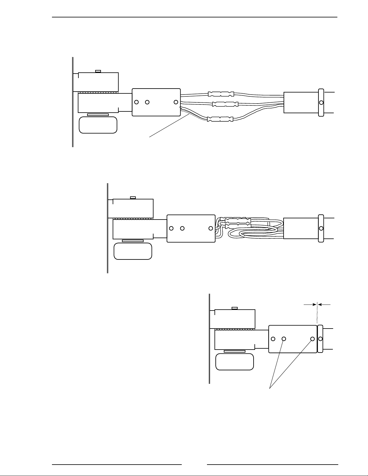
RAISED POLE WARNING SWITCH AND INDICATOR ..................................... 32
Overview.............................................................................................................. 32
Description........................................................................................................... 33
Parts List .............................................................................................................. 34

LGT100 Rev0309
3
List of Tables
Table 1. Lamphead Guide .......................................................................................... 5
Table 2. Recessed Mount Dimensions .................................................................... 11
List of Figures
Figure 1. Assemble Lamphead and Telescopic Pole.................................................. 9
Figure 2. Install Recessed Mount ............................................................................ 11
Figure 3. Install Under Aerial Mount....................................................................... 13
Figure 4. Install Top Mount Telescopic Pole ........................................................... 15
Figure 5. Install Side Mount Telescopic Pole .......................................................... 17
Figure 6. Install Pedestal Mount .............................................................................. 19
Figure 7. Install Tripod Quick Release Bracket Set................................................. 21
Figure 8. Install Portable Light Quick Release Bracket .......................................... 23
Figure 9. Install Contour and Flat Brow Mounts..................................................... 25
Figure 10. Bulb Replacement Optimum and Focus................................................. 27
Figure 11. Bulb Replacement NightMaster ............................................................. 29
Figure 12. No-Scratch ............................................................................................. 31
Figure 13. Raised Pole Warning Switch Housing Locations ................................... 33
Figure 14. Raised Pole Warning Switch Parts List .................................................. 34

LGT100 Rev0309
4
INTRODUCTION
Overview
OPTIMUM Lampheads utilize a super-efcient design to offer a maximum transfer
of light from bulb to scene. The newest addition to the FRC lighting series includes
HIR and HID bulb options not available on classic Focus lights.
FOCUS Low Prole Lampheads introduced the concept of re-directing light with
50 parabolic curved and aimed surfaces. The innovative design directs light where it
is needed. The low prole of the classic FOCUS offers mounting options that many
other lights cannot.
NIGHTMASTER Lampheads are affordable scene lights that have a proven track
record on emergency apparatus. Simple, functional, and available in multiple styles
and mounting congurations.
Features
EFFICIENCY The brightest and best designed lights in the industry. A unique
reector design transfers more light from the bulb to the scene.
NO WASTED LIGHT Focus 100% of the light directly where it is needed.
RELIABLE and PROVEN Manufactured from heavy duty, thick extruded
aluminum for long life and many hours of dependable performance. Proven
under actual emergency situations.
COMPACT Focus lights will not take up valuable space on your vehicle.
ATTRACTIVE Modern design and stylish look of all our lights enhances the
appearance of emergency apparatus.
VERSATILE Choose from 70W to 1500W and from 12V to 240V capabilities.
MOUNTING CHOICES FRC lampheads can be mounted virtually anywhere as
telescopic poles, portable, xed, brow mounted, recessed, or under aerial.
OPTIONS Include multiple size mounting brackets, costum length poles, wire
guard, on/off power switch, raised pole indicator,and no scratch for Focus.
SAFETY TWIST LOCK Easy to use and standard on all FRC telescopic poles,
the locking mechanism has no metal to metal contact, it can not jam or be over
tightened.

LGT100 Rev0309
5
Series
O=Optium
F=Focus
L=NightMaster
Lapmhead
Style
Bulb Type Watts Volts Amps
O, F H70 HID 70 12 6.0
O, F H15 HID 150 12 12.5
O E70 HID 70 24 3.0
O E15 HID 150 24 6.25
F D15 Quartz Halogen 150 12 12.5
F D30* Quartz Halogen 300 12 25.0
F H30 Quartz Halogen 300 24 12.5
L DT0 Quartz Halogen 250 12 20.0
L TC0 Quartz Halogen 300 12 25.0
O, F, L S30 Quartz Halogen 300 120 2.5
O, F, L S50 Quartz Halogen 500 120 4.2
L P50 Quartz Halogen 500 120 4.2
O, F S75 Quartz Halogen 750 120 6.3
O, F, L M10 Quartz Halogen 1000 120 8.3
O, F S72 Quartz Halogen 750 240 3.1
O R90 HIR 900 240 3.75
O, F, L M12 Quartz Halogen 1000 240 4.2
O, F, L M15 Quartz Halogen 1500 240 6.25
* Two 150 watt bulbs are installed.
RESTRICTION NOTES
12/24 VDC lampheads are not available on 600 and 700 type mounts.
240 VAC lampheads are not available on 700 type mounts.
LT series lampheads are not available on 200, 230, 250, 300, 800, and 850 type mounts.
FOCUS HID lamphead is only available on 800 and 850 type mounts.
.
Table 1. Lamphead Guide
Specications
Note: All Optimum, Focus, and NightMaster lampheads are available
seperately or as part of a lighting assembly.

LGT100 Rev0309
6
SAFETY SUMMARY
FRC lighting products are engineered and manufactured with safety in mind. It is
critical that FRC scene lights are installed, maintained, and operated correctly. Read and
understand all instructions before installing, performing maintenance, or operating.
All components, equipment, and installation procedures shall conform to NFPA
1901, Standard for Automotive Fire Apparatus and NFPA 70 National Electrical
Code.
The following safety precautions shall be observed while performing procedures
in this manual.
General Safety Precautions
Ensure power is off prior to connecting or disconnecting wires and plugs or
performing maintenance.
Scene lighting lampheads are designed for outdoor use and will be extremely
hot when operating. Do not use in areas of limited ventilation.
Installation Safety Precautions
Ensure power is off prior to connecting wires or cable to the power source.
Connect only to the type of power source as indicated on the lamphead
identication label.
Ensure an appropriate sized circuit protection device is installed (circuit breaker
or fuse).
Use a minimum of 16 AWG wire to connect AC lights and 12 AWG to connect
DC lights.
FRC lights are intended for mounting to a noncombustible surface only. Do not
install insulation within 76 mm (3 in) of any part of the light, lighting xture,
or its components.
Install approved rubber or plastic grommets or bushings where wires or cable
will pass through a surface.
Ensure all wire connectors or terminals provide a positive mechanical and
electrical connection.
Electrical connections not enclosed in a box must be covered with an insulation
equivalent to that on the conductors.
Lampheads will be extremely hot when operating, do not mount such that personnel
or equipment could inadvertently come in contact with the lamphead.
Recessed lights require a minimum of 3 inch clearance between wall insulation
and the light housing.

LGT100 Rev0309
7
Operation Safety Precautions
Operate portable lighting products only from the type of power source indicated
on the identication label.
During operation use the handle to move the light, the housing will be extremely
hot.
Ensure that all lighting components are clear of obstructions when raising
telescopic poles.
Ensure that telescopic poles are lowered and stowed before moving the
vehicle.
Maintenance Safety Precautions
Ensure power is off prior to removing the front glass or opening covers.
Do not operate the light with the front glass removed or cover opened.
Ensure replacement bulbs have the same voltage and wattage.
When handling a new quartz halogen, HIR, or HID bulb avoid touching it except
on the at seal at either end.
Use a clean soft cloth to wipe the reector clean if necessary, do not use liquid
or aerosol cleaners.

LGT100 Rev0309
8
INSTALLATION INSTRUCTIONS
Install Lamphead on Telescopic Pole
Lampheads and telescopic poles are shipped apart and need to be assembled
Note: The 512 telescopic pole must be installed before the lamphead is
attached if the small diameter hole is used. Refer to Install Models 510,
512 Top Mount Telescopic Poles.
1. Place the lamphead and the pole on a at surface.
2. Connect the lamphead wires to the pole wires. (Refer to Figure 1.)
a. Ensure that 3/8 inch of bare conductor shows at the end of each wire.
b. Insert the wires in the butt connectors and crimp.
For DC lights:
Connect black to black, white to red.
For AC lights:
Connect black to black, white to white, silver braid to green.
3. Ensure the crimps are tight. (Test by lightly tugging on the wires.)
4. Loop the excess wire in a zig-zag fashion to take up the slack.
Note: Ensure that the wires are not caught and squeezed by the lip of the
pole. If this happens the wire insulation may be cut and short the wires
to the pole.
5. Slide the lamphead onto the pole tucking the wires into the pole.
6. Apply thread lock and tighten the set screws to secure the lamphead on the pole.
(A medium strength locking compound like Loctite blue is recommended.)

LGT100 Rev0309
9
For DC Powered Lights:
Connect black to black, white to red
For AC Powered Lights:
Connect black to black, white to white, silver braid to green.
Figure 1. Assemble Lamphead and Telescopic Pole
Dimension A should be less than 0.015"
(The thickness of a folded piece of paper).
If A is larger, a wire is probably caught.
Disassemble and check the for wire
insulation damage. If there is no damage,
reassemble.
Loop the excess wire in a
zig-zag to take up the slack
and tuck into the pole.
Slide the lamphead assembly onto the pole.
Make sure that the wires are not caught and
squeezed by the lip of the pole.
Note: The 512 telescopic pole must be
installed before the lamphead is attached
if the small diameter hole is used. Refer
to Install Models 510, 512 Top Mount
Telescopic Poles.
Apply thread lock and
tighten the set screws.
A
BLACK
WHITE
SILVER
BRAID
BLACK
WHITE
GREEN
DC powered lights will
only have two wires.
Green Wire
Optimum lamphead only.

LGT100 Rev0309
10
Install Recessed Mount Models 200, 230, 250
1. Measure and mark mounting location for cutout.
2. Cut out mounting hole.
3. Place the light in position to check for fit and mark mounting screw
locations.
4. Double check the clearance around and behind the light housing. Recessed
lights require a minimum of 3 inch clearance between wall insulation and the
light housing.
5. Drill mounting screw holes.
Note: Wires may need to be connected before installing the recessed light.
6. Ensure that approved strain relief for the wiring is installed.
7. Secure the housing with mounting screws.
Wiring
12/24 VDC
Connect the BLACK wire to GROUND.
Connect the RED (or WHITE) wire to POWER.
120/240 VAC
Connect the SILVER BRAID or GREEN wire to chassis GROUND.
Connect the WHITE wire to RETURN.
Connect the BLACK wire to POWER.
FCA200
OPA200, OPA230
OPA250

LGT100 Rev0309
11
Figure 2. Install Recessed Mount
Model W D H W2H2
FCA200-
D15, H30, S30, S50, S72, S75 11 2 5 5/8 9 3/4 4 1/4
D30, M10, M12, M15 17 1/2 25 5/8 16 1/8 4 1/4
OPA200-
S30, S50, S72, S75 11 2 5 5/8 9 3/4 4 1/4
M10, M12, M15, R90 17 1/2 25 5/8 16 1/8 4 1/4
OPA230-
E15, E70, H15, H70 10 3/16 3 1/4 4 3/4 8 3/4 3 7/8
OPA250-
S30, S50, S72, S75 11 3/16 4 1/8 7 1/2 9 9/16 5 3/4
M10, M12, M15, R90 16 9/16 3 1/4 7 1/2 15 5 3/4
Note: W2and H2will be
the cutout dimensions.
OPA250
FCA200
OPA200
OPA230
OPA230 is the only recessed
light available with HID bulb.
Table 2. Recessed Mount Dimensions
Hardware Recommendations
For 200 mounts:
10-32 SS
Hardware Recommendations
For 230 mounts:
1/4-20 SS
Hardware Recommendations
For 250 mounts:
10-32 SS
H
W
W2
H2
D1 1/4"
W
W2
HH2
D3 3/4"
W
H2
W2
H
D3 1/8"
W
W2
H
D
H2
1 3/4"

LGT100 Rev0309
12
Install Aerial Mount Models 300
Before mounting check the identication label on the lamphead for specic voltage
and current requirements. Check that the length of the power cord is correct.
Note: Before drilling holes place the light in position to check for t. Ensure
that the lamphead will clear all obstructions.
1. Place the light in position.
2. Mark the mounting hole locations and through hole for the wiring. Use the
lamphead and attached brackets as a template.
3. Drill mounting holes.
4. Secure the mounting bracket(s). Use 5/16-18 SS hardware.
5. Ensure that approved strain relief for the wiring is installed.
6. Adjust the lamphead angle by loosing the nuts at the bracket pivot point, set
at desired position and tighten nuts.
Wiring
12/24 VDC
Connect the BLACK wire to GROUND.
Connect the RED (or WHITE) wire to POWER.
120/240 VAC
Connect the GREEN wire to chassis GROUND.
Connect the WHITE wire to RETURN.
Connect the BLACK wire to POWER.
FCA300

LGT100 Rev0309
13
Figure 3. Install Under Aerial Mount
Note: It is best to use the lamphead and attached
brackets as a template to mark mounting holes.
Adjust the lamphead angle
by loosing the nuts at the
bracket pivot point.
Required Clearance
Aimed directly forward 4 inches
Aimed at 30° downward 6.5 inches
Aimed at 45° downward 6.75 inches
Aimed directly down 7.5 inches
Hardware Recommendations
For 300 mounts:
5/16-18 SS

LGT100 Rev0309
14
Install Top Mount Telescopic Pole Models 510, 512
When positioning a telescopic pole ensure that the lamphead will clear all
obstructions and the twist lock will be accessible.
Note: The 512 telescopic pole should be installed before the lamphead is
attached. Two set screws allow the ange to be removed and the pole will
t up through a 1 5/8" hole. To install a fully assembled 512 pole down
through the roof, a 2 1/2" hole will be needed so the handle and twist lock
will t through.
1. Check the light position for t and freedom of operation
2. Mark the footprint of the mounting ange.
3. Drill mounting holes.
Note: The 512 requires a bead of RTV or similar sealant be applied between
the mounting surface and the bottom outer edge of the ange.
4. For 512 apply a bead of sealant around the bottom outer edge of the ange.
5. Secure the mounting ange. Use 1/4-20 SS hardware. Install a backing plate
if necessary for a sturdy mounting.
6. Ensure that approved strain relief for the wiring is installed.
Wiring
12/24 VDC
Connect the BLACK wire to GROUND.
Connect the RED wire to POWER.
120/240 VAC
Connect the GREEN wire to chassis GROUND.
Connect the WHITE wire to RETURN.
Connect the BLACK wire to POWER.
510
Top Mount
Pull Up
512
Thru-The-Roof
Push Up

LGT100 Rev0309
15
Figure 4. Install Top Mount Telescopic Pole
Drawings may not be to scale.
DO NOT USE AS A TEMPLATE
Round or Square
Flange
1 3/4"
Diameter
Cutout
2 5/8"
1 7/8"
Flange
Diameter
3 1/4"
510
Top Mount
Note: The 512 telescopic pole
should be installed before the
lamphead is attached. Two set
screws allow the ange to be
removed and the pole will t
up through a 1 5/8" hole. To
install a fully assembled 512
pole down through the roof, a
2 1/2" hole will be needed so
the handle and twist lock will
t through.
512
Thru-The-Roof Mount
1 5/8"
Diameter
Cutout
2 1/2"
Diameter
Cutout
Apply a bead of
sealant around the
bottom outer edge
of the ange.
3"
Flange
Diameter
4"
Hardware Recommendations
For 510, 512 mounts:
1/4-20 SS

LGT100 Rev0309
16
Install Side Mount Telescopic Pole Models 530, 540,
542
When positioning a telescopic pole ensure that the lamphead will clear all
obstructions and the twist lock will be accessible.
1. Place the light in position to check for t and freedom of operation.
2. Slide the brackets up or down into required position. The set screws may need
to be loosened.
3. Tighten set screws.
4. Mark the footprint of the mounting bracket(s).
5. Drill mounting holes.
6. Secure the mounting bracket(s). Use 5/16-18 SS hardware. Install a backing
plate if necessary for a sturdy mounting.
7. Ensure that approved strain relief for the wiring is installed.
Wiring
12/24 VDC
Connect the BLACK wire to GROUND.
Connect the RED wire to POWER.
120/240 VAC
Connect the GREEN wire to chassis GROUND.
Connect the WHITE wire to RETURN.
Connect the BLACK wire to POWER
530
Side Mount
Push Up
540
Side Mount
Pull Up
542
Side Mount
Pull Up
Typical Bracket
Slide bracket up or
down into required
position and tighten
set screws.

LGT100 Rev0309
17
Figure 5. Install Side Mount Telescopic Pole
Drawings may not be to scale.
DO NOT USE AS A TEMPLATE
3 13/16"
1"
2"
3"
Side Mount Bracket Footprint
The footprint is the same for
all side mount and steady rest
brackets.
3"
1 1/2"
3"
2 1/8"
530, 540, 542
Side Mount Brackets
530, 540, 542
Flush Mount Brackets
Hardware Recommendations
For 530, 540, 542 mounts:
5/16-18 SS

LGT100 Rev0309
18
Install Pedestal Mount Models 570, 580
When positioning a pedestal mount light ensure that the lamphead will clear all
obstructions.
1. Place the light in position to check for t and freedom of operation.
2. Mark the footprint of the mounting ange/bracket.
3. Drill mounting holes.
4. Ensure that approved strain relief for the wiring is installed.
5. Secure the mounting ange/bracket. Use 5/16-18 or 1/4-20 SS hardware. Install
a backing plate if necessary for a sturdy mounting.
Wiring
12/24 VDC
Connect the BLACK wire to GROUND.
Connect the RED (or WHITE) wire to POWER.
120/240 VAC
Connect the SILVER BRAID or GREEN wire to chassis GROUND.
Connect the WHITE wire to RETURN.
Connect the BLACK wire to POWER.
OPA570
FCA580

LGT100 Rev0309
19
Figure 6. Install Pedestal Mount
Drawings may not be to scale.
DO NOT USE AS A TEMPLATE
Side Mount Bracket Footprint
The footprint is the same for
all side mount and steady rest
brackets.
3"
1 1/2"
3"
2 1/8"
580
Side Mount Brackets
570
Pedestal Mount
5/8"
Diameter
Cutout
2 7/8"
Flange
Diameter 3
1/2"
Hardware Recommendations
For 570, mounts:
1/4-20 SS
Hardware Recommendations
For 580, mounts:
5/16-18 SS

LGT100 Rev0309
20
Install Quick Release Bracket Set for Tripod Models
600, 642, 656
The quick release mounting bracket set will hold an FRC tripod securely on the
vehicle. The mounting bracket set consists of a lower base into which the bottom of
the tripod legs rest, and an upper locking bracket, which has a quick release knob on
the right side.
1. Place the tripod in position to check for t.
Note: The mounting brackets are aligned left and not centered on each
other.
2. Mark the mounting hole locations.
a. Align the left sides of the brackets and the left side mounting holes for
the tripod to t correctly.
b. The upper bracket is mounted with the pull knob to the right side.
c. Use the brackets as templates.
Helpful Hint: Mount the bottom bracket rst. Attach the quick release bracket
to the hole on the upper slide casting of the tripod. Rest the tripod legs
in the base, and push the upper bracket in position ush to the mounting
surface. Mark the top bracket hole locations.
3. Dill the mounting holes. The mounting brackets are predrilled for 1/4-20
hardware.
Note: Tripods with Focus lampheads require that 3/4" spacers be installed
between the mounting surface and the brackets so the back of the lamphead
will clear the mounting surface.
4. Install the mounting brackets (and spacers with Focus lamphead).
642
Tripod
w/Focus
Lamphead
Quick Release Bracket Set
(Shown with Focus lamphead spacers.)
This manual suits for next models
2
Table of contents
Other FRC Lighting Equipment manuals
Popular Lighting Equipment manuals by other brands

GVM
GVM GVM-480LS manual

Strand
Strand Acclaim LED PLE quick start guide

Lithonia Lighting
Lithonia Lighting ELU 4 installation instructions

MICROPURE
MICROPURE 3600 Installation & operation manual

Chroma
Chroma Color One 100 user manual

Home Accents Holiday
Home Accents Holiday TY477-1611-0 Use and care guide