Speck pumpen BADU Jet Perla User manual

Inhaltsverzeichnis
05/2013 VG 766.2330.061 EN 35
EN Original Operating Instructions for
BADU®Jet
BADU®JetBADU®Jet
BADU®Jet

1 Manual Introduction
36 EN VG 766.2330.061 05/2013
Table of Contents
1Manual Introduction..................................................................38
1.1 Preface...............................................................................38
1.2 Related Documentation......................................................38
1.2.1 Icons and Symbols..................................................38
2Safety .........................................................................................40
2.1 Introduction ........................................................................40
2.1.1 Possible Misuse ......................................................40
2.2 Precautions and Qualifications...........................................40
2.3 Safety Regulations .............................................................41
2.4 Protective Cover.................................................................41
2.5 Structural Changes and Replacement Parts ......................41
2.6 Signs 41
2.7 Other Risks ........................................................................42
2.7.1 Falling Parts ............................................................42
2.7.2 Rotating Parts .........................................................42
2.7.3 Electrical Power ......................................................42
2.7.4 Hot Surfaces ...........................................................43
2.7.5 Entrapment Hazard.................................................43
2.7.6 Entrapment Hazard of sensitive body parts. ...........43
2.8 Malfunctions .......................................................................43
2.9 Prevention of Material Damage..........................................44
2.9.1 Leakage and Burst Pipes ........................................44
2.9.2 Protection against Running Dry ..............................44
2.9.3 Overheating ............................................................44
2.9.4 Seized Pump...........................................................44
2.9.5 Drainage .................................................................44
2.9.6 Frost protection .......................................................45
3Description ................................................................................46
4Transport and Interim Storage.................................................47
4.1 Lifting the counter swim unit...............................................47
5Installation .................................................................................48
5.1 Location..............................................................................48
5.1.1 Mounting site...........................................................48
5.1.2 Checklist .................................................................48
5.1.3 Position ...................................................................48
5.1.4 Securing the unit .....................................................48
5.1.5 Insert the brass dowels ...........................................48
5.1.6 Secure the unit........................................................48

1 Manual Introduction
05/2013 VG 766.2330.061 EN 37
5.1.7 Distance equalization..............................................48
5.1.8 Power supply ..........................................................48
5.2 Assembly Recommendation...............................................49
5.3 Electrical Connection..........................................................49
5.4 Additional parts required ....................................................50
6Start Up ......................................................................................51
Protection against Running Dry..........................................51
6.1 Filling the pump..................................................................51
6.2 Start-up after prolonged downtime .....................................52
6.3 Switching ON .....................................................................52
7Operation ...................................................................................53
7.1 Operating the overhang counter swim unit.........................53
7.1.1 Turning the unit ON and OFF..................................53
7.1.2 Air Regulation Function...........................................53
7.1.3 Light operation ........................................................53
7.1.4 Setting the ball nozzle.............................................53
7.1.5 Cover damage. .......................................................53
7.1.6 Optimal water level..................................................53
7.2 Massage hose....................................................................54
7.2.1 Instructions for the massage hose. .........................54
7.2.2 Air regulation and the massage hose......................54
8Malfunctions ..............................................................................55
8.1 Failures ..............................................................................55
8.1.1 Overload switch has triggered.................................56
9Maintenance/Service.................................................................57
9.1 Care Instructions ................................................................57
10 Appendix I..................................................................................58
10.1 Technical Information.........................................................58
10.2 Dimensions ........................................................................59
10.3 Wiring diagrams .................................................................60
10.4 Information on Safety Position Switch................................61
10.5 Securing the unit to the ground ..........................................62
10.6 Securing the unit with the telescopic support foot. .............64
10.7 Various Drawings ...............................................................65

1 Manual Introduction
38 EN VG 766.2330.061 05/2013
1 Manual Introduction
1.1 Preface.
This manual contains important information for reliable and efficient
operation of the overhang counter swim units. Compliance with the
operating instructions is of vital importance to ensure reliability and a
long service life of the product and to avoid any risks.
These units have been developed using state of-the-art-technology and
manufactured with utmost care and have been subjected to the strin-
gent Speck Pumpen testing facilities and continuous quality control.
Speck Pumpen Verkaufsgesellschaft GmbH does not accept any liabil-
ity for damage and injury caused by not observing the directions and
instructions in this manual. This also applies in cases of carelessness
during the installation procedure, use and maintenance of the product.
Non-compliance with the safety instructions can jeopardize the safety of
personnel, the environment and the product itself. Non-compliance with
the instructions will also lead to forfeiture of any and all rights to claims
for damages
Keep the instructions available for the life of the product.
Make sure the instructions are accessible to all operators and ser-
vice personnel.
Ensure the instructions are passed on to each owner or user of the
product.
1.2 Related Documentation
Replacement parts list
Packing list
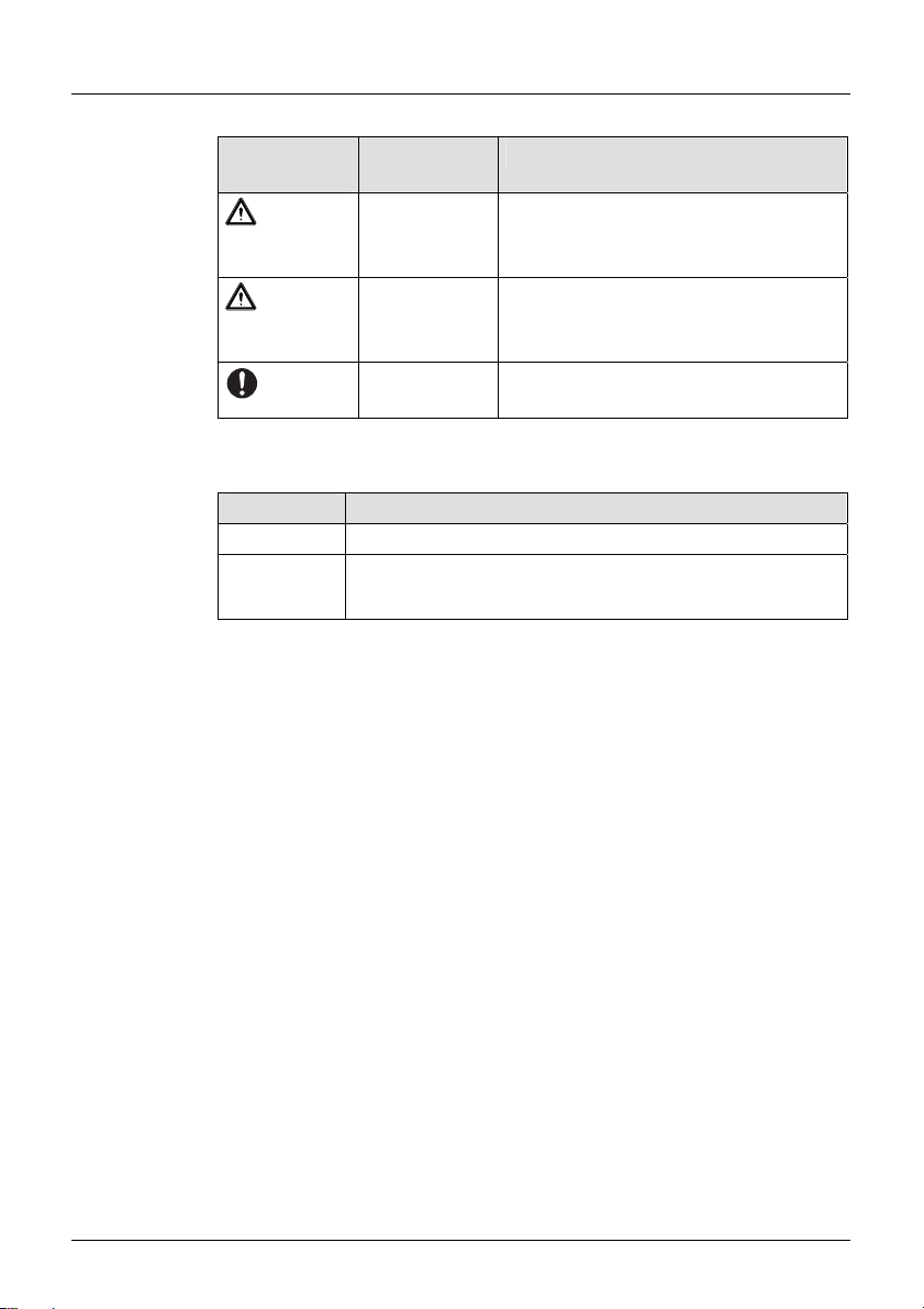
1.2.1 Icons and Symbols
Icons and symbols are used to introduce safety instructions whose non-
observance can lead to personal injury.
Always read and follow the warnings.
Icons &
Symbol
Warning Meaning
DANGER Physical Danger
Non-observance can result in death
or severe injury.
1 Manual Introduction
05/2013 VG 766.2330.061 EN 39
Icons &
Symbol
Warning Meaning
WARNING Physical Danger
Non-observance can result in death
or severe injury.
CAUTION Physical Danger
Non-observance can result in per-
sonal injury.
– Instructions to prevent material dam-
age, and optimize operation.
To ensure easy and correct operation, important technical information
in a step by step procedure have been highlighted.
Symbol Meaning
Single step action
1.
2.
Multi-step action
Follow the sequence of steps.
This manual suits for next models
2
Table of contents
Other Speck pumpen Lighting Equipment manuals


