Frick LZWII-2M Owner's manual

This manual contains rigging, assembly, start-up, and maintenance
instructions. Read thoroughly before beginning installation. Failure
to follow these instructions may result in personal injury or death,
damage to the unit, or improper operation.
LaZerWeld II Plate Heat Exchangers
LZWII-2M, LZWII-4B, LZWII-4E, LZWII-6B,
LZWII-8K, LZWII-8B, and LZWII-12M
Check www.FrickCold.com for the latest version of this publication.
Form 190.210-IOM (FEB 2020)
INSTALLATION–OPERATION–MAINTENANCE
File: SERVICE MANUAL–Section 070
Replaces: NOTHING
Dist: 3, 3a, 3b, 3c

190.210-IOM (FEB 20)
Page 2
LAZERWELD II PLATE HEAT EXCHANGER
INSTALLATION - OPERATION - MAINTENANCE
Indicates an imminently hazardous situation which, if not avoided, will result in death or seri-
ous injury.
Indicates a potentially hazardous situation or practice which, if not avoided, will result in death
or serious injury.
SAFETY PRECAUTION DEFINITIONS
Indicates a potentially hazardous situation or practice which, if not avoided, will result in damage
to equipment and/or minor injury.
Indicates an operating procedure, practice, etc., or portion thereof which is essential to highlight.
WARNING
CAUTION
DANGER
NOTICE
Contents
General Information
Preface..............................................................................3
Safety considerations........................................................3
Warranty conditions.......................................................... 3
Advice...............................................................................3
Environmental compliance ................................................ 3
Unpacking.....................................................................3
Maintenance................................................................. 3
Scrapping .....................................................................3
Main components.............................................................. 3
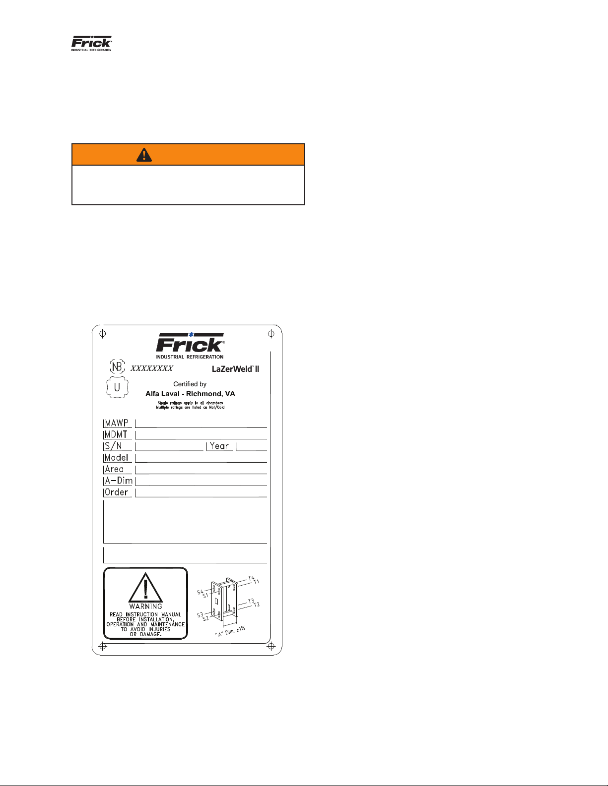
Nameplate......................................................................... 5
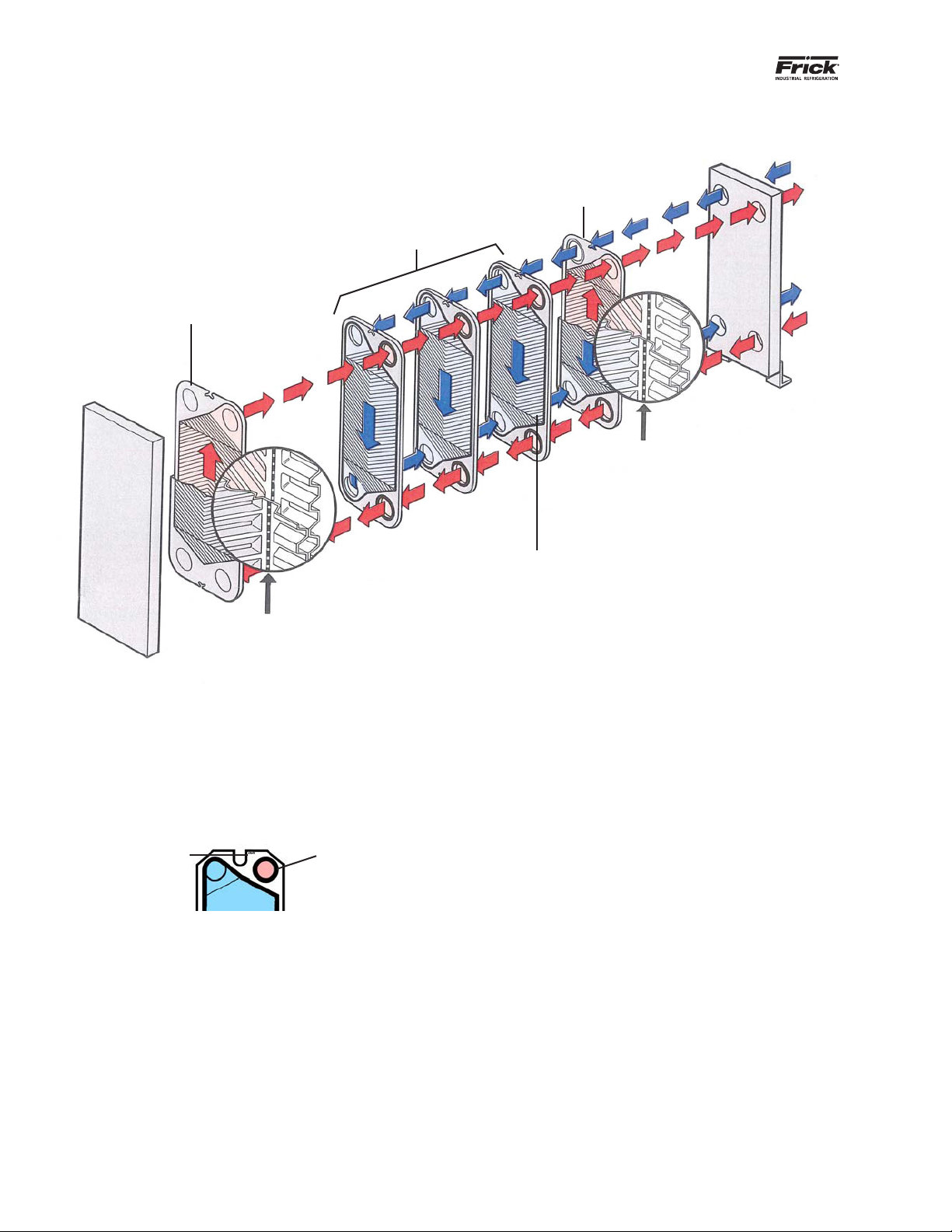
Function ............................................................................5
Identication of plate side................................................. 6
Installation
Before installing ................................................................ 7
Requirements.................................................................... 7
Space ...........................................................................7
Foundation ...................................................................7
Elbow ...........................................................................7
Shut-off valve...............................................................7
Drip tray (optional) ....................................................... 7
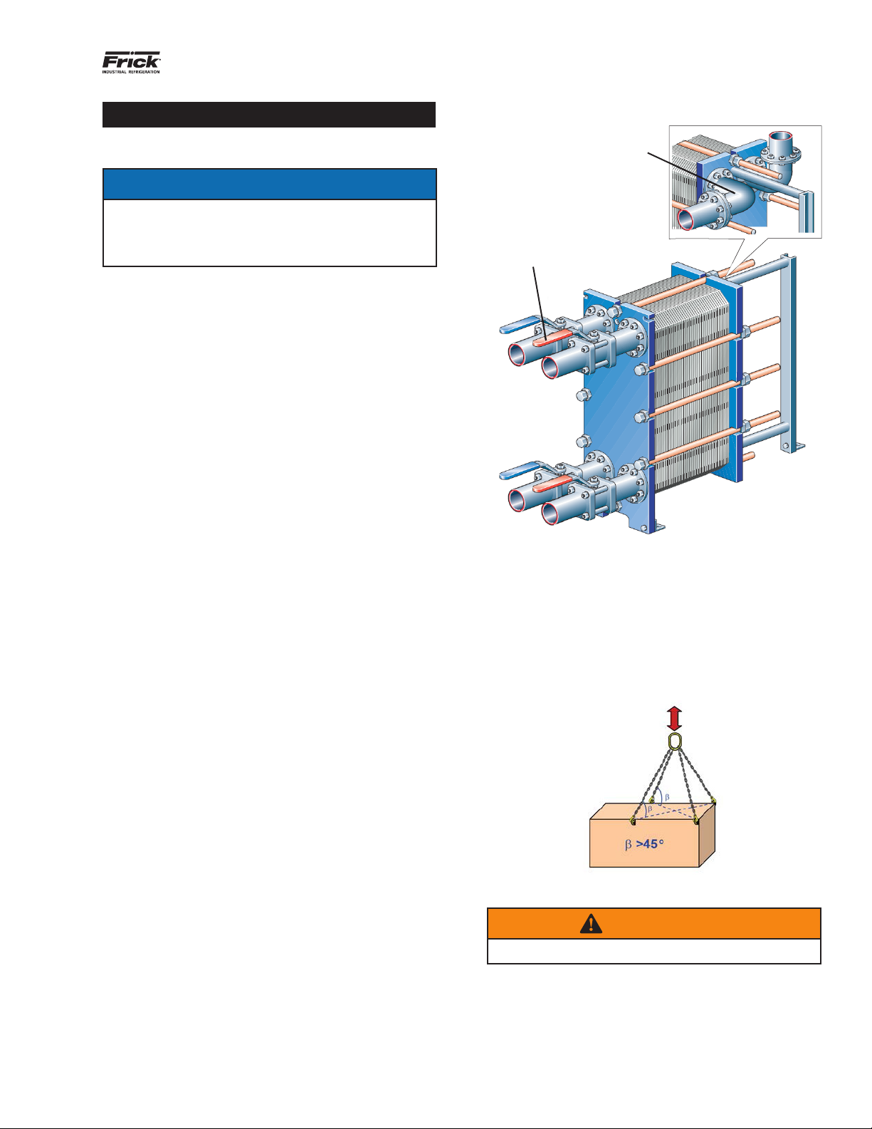
Connections in the pressure plate ................................7
Lifting ...............................................................................7
Raising .............................................................................8
Connecting to the system .................................................9
Operation
Start-up ..........................................................................11
Unit in operation ............................................................. 12
Shut-down ...................................................................... 12
Maintenance
Cleaning-In-Place (CIP)...................................................13
Manual cleaning .............................................................. 13
Opening......................................................................13
Manual cleaning of opened units..................................... 15
Deposits removable with water and brush ................. 15
Deposits not removable with water and brush ..........16
Regasketing .................................................................... 16
Clip-on and Clip-Grip ................................................. 16
Adhesive tape............................................................. 17
Glued gaskets............................................................. 17
Closing ............................................................................17
Max tightening torque................................................18
Pressure test after maintenance ..................................... 19
Storage of the LZWII....................................................... 19
Storage in packing box...............................................19
Taken out of service...................................................20
Installation after long-term storage ........................... 20

190.210-IOM (FEB 20)
Page 3
LAZERWELD II PLATE HEAT EXCHANGER
INSTALLATION - OPERATION - MAINTENANCE
General Information
PREFACE
This manual provides information needed to install, oper-
ate and carry out the maintenance of the LaZerWeld II
(LZWII) plate heat exchanger.
SAFETY CONSIDERATIONS
Use and maintain the LZWII in accordance with FRICK’s
instructions in this manual. Faulty handling of the heat
exchanger may result in serious consequences with inju-
ries to persons and/or property damage. FRICK does not
accept responsibility for any damage or injury that has
resulted from not following the instructions in this manual.
Use the heat exchanger in accordance with the specied
conguration of material, media types, temperatures, and
pressure for the specic LZWII.
The following models are covered in this manual:
• LZWII-2M
• LZWII-4B
• LZWII-4E
• LZWII-6B
• LZWII-8K
• LZWII-8B
• LZWII-12M
WARRANTY CONDITIONS
The warranty conditions are usually included in the signed
sales contract before the order of the delivered LZWII.
Alternatively, the warranty conditions are included in
the sales offer documentation or with a reference to the
document specifying the valid conditions. If faults occur
during the specied warranty period, always consult your
local FRICK Representative for advice.
Report the date when the heat exchanger was put into
operation to the local FRICK Representative.
ADVICE
Consult your local FRICK representative for information on
the following:
• New plate pack dimensions if you intend to change the
number of cassettes (twin plates)
• Selection of gasket material if operating temperatures
and pressures are permanently changed, or if another
medium is to be processed in the LZWII
ENVIRONMENTAL COMPLIANCE
FRICK endeavours to perform its own operations as cleanly
and efciently as possible, and to take environmental
aspects into consideration when developing, designing,
manufacturing, servicing, and marketing its products.
Unpacking
Packing material consists of wood, plastics, cardboard
boxes and, in some cases, metal straps.
• Wood and cardboard boxes can be reused, recycled, or
used for energy recovery.
• Ensure plastics are recycled or burnt at a licensed
waste incineration plant.
• Send metal straps for material recycling.
Maintenance
• Send all metal parts for material recycling.
• Oil and all non-metal wear parts must be taken care of
in agreement with local regulations.
Scrapping
At end of use, recycle the equipment in accordance with
the relevant, local regulations. Besides the equipment
itself, any hazardous residues from the process liquid must
be considered and dealt with in a proper manner. When in
doubt, or in absence of local regulations, contact the local
FRICK sales company.
MAIN COMPONENTS
The following section details the main components of the
LZWII.

190.210-IOM (FEB 20)
Page 4
LAZERWELD II PLATE HEAT EXCHANGER
INSTALLATION - OPERATION - MAINTENANCE
Table 1: LZWII main components
Bolt protection Plastic tubes that protect the threads of the tightening bolts
Carrying bar Carries the plate pack and the pressure plate
Frame plate Fixed steel plate with a number of port holes for the connection of the piping system. The carrying
and guiding bars are supported by the frame plate
Guiding bar Keeps the channel plates and the pressure plate in line at their lower end
Plate pack
Heat is transferred from one medium to the other through the plates. The plate pack consists of semi
welded plates in pairs which form a cassette (twin plate), gaskets, and distance sheets. The measure
of the plate pack is the measurement between the frame plate and pressure plate. Refer to the sub-
mittal drawing for this dimension
Port holes with stud
bolt connections
Port holes through the frame plate allow the media to enter into or exit from the heat exchanger.
Different types of connections can be used to connect the piping system to the apparatus. Threaded
stud bolts around the port holes secure the connections to the apparatus. The port holes may be
protected against corrosion by metal linings. The LZWII can be equipped with different connection
types. For details, refer to LZWII drawings supplied with product
Flanged pipe
connection Illustration of connection type used for LZWII-4B
Pressure plate Moveable steel plate that can contain a number of port holes for the connection of the piping system.
Covers Used as blind ange or inspection cover at the LZWII port holes
Supporting column Supports carrying and guiding bars
Tightening bolts Compress the plate pack between the frame and pressure plate
Figure 1: LZWII main components
Port hole with stud
bolt connections
Tightening bolts
Frame plate
Distance sheets
Carrying bar
Bolt protection
Supporting column
Pressure plate
Guiding bar
Plate pack
Partition plate
Flanged pipe connection

190.210-IOM (FEB 20)
Page 5
LAZERWELD II PLATE HEAT EXCHANGER
INSTALLATION - OPERATION - MAINTENANCE
NAMEPLATE
On the nameplate you can nd the type of unit, manufac-
turing number, and manufacturing year. You can also nd
pressure vessel details in accordance with the applicable
pressure vessel code. The nameplate is most commonly
xed to the frame plate, or the pressure plate.
WARNING
For each unit, the mechanical design pressures and
temperatures are marked on the nameplate. These
must not be exceeded.
The mechanical design pressure and the design tempera-
ture as given on the name plate are the values to which
the plate heat exchanger (PHE) is approved to the pressure
vessel code in question. The mechanical design tempera-
ture may exceed the maximum operating temperature
established for the gasket material lifetime. If the operat-
ing temperatures as specied on the assembly drawing are
to be exceeded, consult the supplier.
Figure 3: Nameplate
Material No.
FRICK Sales Order No.
Tag No. (Optional)
FOR PARTS, SERVICE AND AFTER MARKET ASSISTANCE
CALL 1-717-762-2121 | www.frickcold.com
FUNCTION
The LZWII consists of a set of corrugated metal plates
with port holes for inow and outow of two separate
uids. The plates are arranged as cassettes (twin plates) in
such a way that every second channel is welded, and ev-
ery other channel is gasketed. The heat transfer between
the two uids takes place through the plates. The cassette
concept gives rise to two different types of channel -
welded channels used for the aggresive primary media and
gasketed channels used for the non-aggresive secondary
media.
The plate pack is assembled between a frame plate and
a pressure plate and compressed by tightening bolts. The
plates are tted with a gasket that seals the channel and
directs the uids into alternate channels. The plate cor-
rugation promotes uid turbulence and supports the plates
against differential pressure.

190.210-IOM (FEB 20)
Page 6
LAZERWELD II PLATE HEAT EXCHANGER
INSTALLATION - OPERATION - MAINTENANCE
Figure 4: Cassette arrangement forming the plate pack
IDENTIFICATION OF PLATE SIDE
The A orientation of the cassette is identied by the stamp
with the letter A or the model name, in some cases both,
at the top of the plate. See Figure 4. The separate ring
gaskets always point to the right when the cassette is
oriented as A.
End cassette II
End single plate
Channel cassettes
End cassette I
End single plate
Gasketed channel
created between
two cassettes
(blue)
Two plates which
form the welded
channel inside
the cassette (red)
Identication stamp Ring gasket

190.210-IOM (FEB 20)
Page 7
LAZERWELD II PLATE HEAT EXCHANGER
INSTALLATION
Installation
BEFORE INSTALLING
NOTICE
Before start-up, check that all tightening bolts are
rmly tightened and that you use the correct mea-
surements of the plate pack. See LWZWII drawing
and Closing section.
• To avoid water hammer, do not use fast-closing valves.
• Install safety valves according to current pressure ves-
sel regulations.
• If the LZWII surface temperature is expected to be hot
or cold, insulate the heat exchanger.
• Use protective sheets to cover the plate pack.
• For each model, design pressures and temperatures are
marked on the identication plate. These must not be
exceeded.
• Full vacuum conditions apply at start up for refrig-
eration duties to avoid moisture and air in the heat
exchanger.
REQUIREMENTS
Space
A minimum free space is needed for lifting cassettes in
and out. Refer to the delivered drawing.
Foundation
Install on a at foundation giving enough support to the
frame.
Elbow
To allow easier disconnection of the LZWII, connect an el-
bow to the pressure plate using a ange, directed upwards
or sideways, and with another ange located just outside
the contour of the heat exchanger.
Shut-off valve
To be able to open the LZWII, install shut-off valves at all
connections.
Drip tray (optional)
Depending on the type of uid in the LZWII and the type of
installation, a drip tray (drainage box) may be necessary to
avoid injury to personnel and damage to equipment.
Note: Put the drip tray in place before positioning the LZWII
Connections in the pressure plate
Ensure the plate pack is tightened to the correct dimen-
sion A before the pipe system is connected. Verify on the
nameplate.
Figure 5: Shut-off valve and elbow location
LIFTING
Use straps when lifting the LZWII. Attach the straps as il-
lustrated in with a minimum angle of 45°.
Position straps as illustated in Figure 7 to Figure 10.
Figure 6: Lifting straps
WARNING
Never lift by the connectors or studs.
Shut-off valve
Elbow

190.210-IOM (FEB 20)
Page 8
LAZERWELD II PLATE HEAT EXCHANGER
INSTALLATION
Figure 7: Lifting divice for LZWII-2M and LZWII-4B
Figure 8: Lifting divice for LZWII-6B
Figure 9: Lifting device for LZWII-8K and LZWII-8B
Figure 10: Lifting divice for LZWII-12M
RAISING
This instruction is valid when raising the LZWII after
delivery. The strap is approved for the weight of the heat
exchanger to be used.
CAUTION
The straps is long enough to rotate the PHE without
obstructions. Pay particular attention to the space
required for the support column
1. Place two timber posts on the oor.
2. Lift the LZWII off the pallet using straps.

190.210-IOM (FEB 20)
Page 9
LAZERWELD II PLATE HEAT EXCHANGER
INSTALLATION
3. Position the LZWII on the timber posts.
4. Place straps around one bolt on each side.
5. Lift the LZWII off the timber posts.
6. Lower the LZWII onto the oor in a horizontal position.
CONNECTING TO THE SYSTEM
Remove sealing blind covers from the port holes before
connecting the piping system.
When connecting the piping system, make sure the pipes
do not subject the LZWII to stress or strain.
Before connecting any piping, make sure that no foreign
objects have been left in the system which connects to
the LZWII. Install a strainer or lter with 0.5 mm to 1.0 mm
mesh size to prevent problems with foreign objects in the
piping system.

190.210-IOM (FEB 20)
Page 10
LAZERWELD II PLATE HEAT EXCHANGER
INSTALLATION
This page is intentionally left blank

190.210-IOM (FEB 20)
Page 11
LAZERWELD II PLATE HEAT EXCHANGER
OPERATION
Operation
START-UP
During start-up, check that no visible leakages appear
from the plate pack, valves, or piping system.
NOTICE
If several pumps are included in the system, make
sure you know which one to activate rst.
NOTICE
Make adjustments of ow rates slowly in order to
avoid the risk of pressure surge (water hammer).
Water hammer is a short-lasting pressure peak that
can appear during start-up, or shut-down of a sys-
tem, causing liquids to travel along a pipe as a wave
at the speed of sound. This can cause considerable
damage to the equipment.
NOTICE
Charging liquid ammonia into a refrigeration circuit
under vacuum results in low temperatures. Such
temperature levels might be lower than any elasto-
meric materials can seal against.
In applications where the eld side is used for a two-
phase refrigerant, for example cascade CO2/NH3 ap-
plications, it is very important to ll the two-phase
refrigerant in gas phase. This to avoid temperature
chocks for the gaskets and to avoid temporary leak-
ages due to the natural fact that the metal is shrink-
ing very fast.
1. Before start-up, check that all tightening bolts are
rmly tightened and that the dimension A is correct.
See LZWII drawing.
2. Check that the valve is closed between the pump and
the unit controlling the system ow rate.
3. If there is a valve at the exit, make sure it is fully open.
4. Open the air vent and start the pump.
5. Open the valve slowly.
NOTICE
Avoid rapid temperature changes in the LZWII. With
media temperatures over 212°F (100°C), slowly in-
crease the temperature, preferably at least for one
hour.
Closed
Open
Open
Open slowly

190.210-IOM (FEB 20)
Page 12
LAZERWELD II PLATE HEAT EXCHANGER
OPERATION
6. When all air is expelled, close the air vent.
7. Repeat steps 1 to 6 for the second media.
UNIT IN OPERATION
Make adjustments of ow rates slowly in order to protect
the system against sudden and extreme variations of tem-
perature and pressure.
During operation, check that media temperatures and
pressures are within the limits stated on the LZWII drawing
and identication plate.
SHUT-DOWN
If several pumps are included in the system, make sure
you know which one to stop rst.
1. Slowly close the valve controlling the ow rate of the
pump you are about to stop.
2. After closing the valve, stop the pump.
3. Repeat steps 1 to 2 for the other side for the second
media.
4. If the LZWII is shut down for several days or longer,
drain it. Also drain if the process is shut down and the
ambient temperature is below the freezing temperature
of the media. Depending on the media processed, rinse
and dry the heat exchanger cassettes and connections.
Closed
Closed

190.210-IOM (FEB 20)
Page 13
LAZERWELD II PLATE HEAT EXCHANGER
MAINTENANCE
Maintenance
To keep the LZWII in good condition regular maintenance
is required.
The plates (cassettes) need to be cleaned on a regular ba-
sis. The frequency depends on several factors such as type
of media and temperatures. Three methods can be used
for cleaning. See Cleaning-In-Place (CIP), Manual cleaning,
or a reconditioning at an FRICK authorized service center.
NOTICE
If cleaning in place, use modulating or soft pumps to
avoid high ow rates and pressure shocks.
CLEANING-IN-PLACE (CIP)
The Cleaning-In-Place (CIP) equipment permits cleaning of
the PHE without opening it. Benets of CIP inlcude:
• Removal of fouling and lime scale deposits.
• Passivation of cleaned surfaces to reduce susceptibility
to corrosion.
• Neutralization of cleaning liquids before draining.
See CIP equipment instructions.
WARNING
Use proper protective equipment, such as safety
boots, safety gloves and eye protection, when using
the cleaning agents.
WARNING
Corrosive cleaning liquids can cause serious injuries
to skin and eyes!
FRICK guarantees that plates (cassettes), gaskets, and ad-
hesive cannot be damaged if the procedures and cleaning
agents specied are used.
If CIP is inappropriate, cleaning must be done manually.
See Manual cleaning.
MANUAL CLEANING
To perform manual cleaning it is necessary to open the
LZWII and lift out the cassettes to clean them. Only every
second channel (gasketed) is feasible to clean.
Note: For manual cleaning of heat exchangers in refrigerant ser-
vices, contact your FRICK representative.
Opening
NOTICE
Before opening the PHE check the warranty condi-
tions. If in any doubt, contact a FRICK sales repre-
sentative. See Warranty conditions.
WARNING
If the PHE is hot, wait until it has cooled down to
about 104°F (40°C).
WARNING
If necessary, use proper protective equipment, such
as safety boots, safety gloves and eye protection,
depending on type of media in the PHE.

190.210-IOM (FEB 20)
Page 14
LAZERWELD II PLATE HEAT EXCHANGER
MAINTENANCE
1. Drain the LZWII.
2. Brush the threads of the bolts clean, using a steel
wire brush or the FRICK thread cleaner. Lubricate the
threads with a thin layer of grease, such as Gleitmo
800 Lubriplate or equivalent.
3. Inspect the sliding surfaces of the carrying bar and
clean and grease it.
4. Mark the cassette assembly on the outside with a
diagonal line.
5. Measure and note the dimension A.
NOTICE
Brush the threads of the tightening bolts with a steel-
wire brush and then grease before loosening them.
6. Keep the four bolts in position, according to the gure
below. Loosen the other bolts and remove them.
Inspect
Mark
Keep the two
bolts closest
below the upper
port holes
Keep the two
bolts closest
above the lower
port holes

190.210-IOM (FEB 20)
Page 15
LAZERWELD II PLATE HEAT EXCHANGER
MAINTENANCE
7. Open the remaining four bolts alternately and diago-
nally in two steps, see gures below.
Be careful to ensure that the frame plate and pressure
plate are always in parallel. Skewing of the pressure
plate during opening must not exceed 10 mm (2 turns
per bolt) across the width and 25 mm (5 turns per bolt)
vertically.
a. Loosen the four bolts alternately and diagonally until
the plate package is approximately 5% greater than
the A dimension (1.05A).
b. Loosen the two diagonal pairs of bolts alternately, as
shown in the gure below.
8. Open the plate pack by letting the pressure plate glide
on the carrying bar.
CAUTION
To avoid hand injuries from sharp edges, always wear
protective gloves when handling cassette s and pro-
tective sheets.
NOTICE
Number the Cassettes before removing them.
Cassettes do not need to be removed if cleaning is
done using only water, or without cleaning agent.
WARNING
The plate pack may still contain a small residual
amount of liquid after draining. Depending on the
type of product and type of installation, special ar-
rangements, such as drainage box, may be necessary
to avoid injury to personnel and damage to equip-
ment.
MANUAL CLEANING OF OPENED UNITS
CAUTION
Never use hydrochloric acid with stainless steel
plates. Water of more than 330 ppm Cl may not be
used for the preparation of cleaning solutions. It is
very important that carrying bars and support col-
umns in aluminium are protected against chemicals.
NOTICE
Be careful not to damage the gasket during manual
cleaning.
Deposits removable with water and brush
Cassettes do not need to be removed from the PHE during
cleaning.
Note: For manual cleaning of heat exchangers in refriger-
ant services, contact your FRICK representative
WARNING
If necessary, use proper protective equipment.
Consider risks like loose particles and what kind of
media has been used in the PHE.
A
A

190.210-IOM (FEB 20)
Page 16
LAZERWELD II PLATE HEAT EXCHANGER
MAINTENANCE
1. Start cleaning when the heating surface is still wet and
the cassettes are hanging in the frame.
2. Remove deposits using a soft brush and running water.
3. Rinse with water using a high pressure hose.
Deposits not removable with water and brush
Cassettes must be removed from the PHE during cleaning.
WARNING
Use proper protective equipment, such as safety
boots, safety gloves and eye protection, when using
the cleaning agents.
WARNING
Corrosive cleaning liquids can cause serious injuries
to skin and eyes!
1. Brush with cleaning agent.
2. Rinse immediately with water.
NOTICE
Long exposure to the cleaning agents can damage
the gasket glue.
REGASKETING
These procedures apply to eld gaskets and ring gaskets
afxed to the cassettes using glue free Clip-on tabs.
NOTICE
Before removing the old gaskets check how they
are placed and attached. Especially the end cassette
gasket conguration needs attention.
Clip-on and Clip-Grip
1. Open the LZWII (see Opening) and remove the cassette
that is to have a new gasket.
NOTICE
Before opening the LZWII check the warranty condi-
tions. If in any doubt, contact a FRICK sales repre-
sentative. See Warranty conditions.
2. Remove the old gasket.
3. Ensure that all sealing surfaces are dry, clean, and free
of foreign matter such as fat, grease, or similar.
4. Check the gasket and remove rubber residual before
attaching it.
5. Attach the Clip gasket to the cassette. Slip the gasket
prongs under the edge of the plate. Fix the eld gasket
diagonal using tape on the small tabs. The gasket
placement of the respective cassette type can be ad-
vised by your FRICK representative.
Ring gasket
Field gasket
diagonal
Field gasket

190.210-IOM (FEB 20)
Page 17
LAZERWELD II PLATE HEAT EXCHANGER
MAINTENANCE
NOTICE
Make sure the two gasket prongs of the Clip-on tabs
are in the correct position.
6. Repeat the procedure until all cassettes that are
needed to be regasketed are done. Close the LZWII
(see Closing).
Adhesive tape
The procedures below apply to end cassette gasket sup-
ports and distance rings fastening by means of adhesive
tape around the ports and along the sides.
Adhesive tape (GC1) is a simple and secure way to position
gasket. Afx the gasket to the groove using a special tape
gun which enables you to apply the tape exactly where
required.
1. Open the LZWII (see Opening) and remove the cassette
to be regasketed.
NOTICE
Before opening the LZWII check warranty terms and
conditions. If in doubt, contact your FRICK sales rep-
resentative. See Warranty conditions.
2. Remove the old gasket.
3. You do not need to remove any old tape because the
lm is very thin. Ensure that the gasket groove is clean
and dry however.
4. Apply tape using the tape gun.
5. Attach the gasket to the cassette. The gasket place-
ment of the respective cassette type can be advised by
your FRICK representative.
6. Close the heat exchanger, (see Closing).
Glued gaskets
Use glue recommended by FRICK. Separate gluing instruc-
tions are delivered together with the glue.
Note: Glued gaskets are not allowed in refrigerant side of
the heat exchanger.
CAUTION
Other glues than those recommended can contain
chlorides that can damage the plates.
CAUTION
Do not use sharp tools when removing the glued
gasket to avoid damage to the plates.
CLOSING
Follow the instructions below to ensure that the LZWII is
properly closed.
1. Check that all the sealing surfaces are clean.
2. Brush the threads of the bolts clean using a steel wire
brush or thread cleaner. Lubricate the threads with a
thin layer of grease, such as Gleitmo 800 Lubriplate or
equivalent.
3. Attach gaskets to the cassettes or check that all the
gaskets are properly attached.
NOTICE
If the gasket is wrongly positioned, it can rise out
of the gasket groove or be positioned outside the
groove.
4. Insert the cassettes in alternate directions and with
the gaskets turned towards the frame plate or pres-
sure plate as specied on the plate hanging list. Use
the marked line that was done when the LZWII was
opened. See step 3 in the Opening section.

190.210-IOM (FEB 20)
Page 18
LAZERWELD II PLATE HEAT EXCHANGER
MAINTENANCE
5. If the cassettes are correctly assembled, the edges
form a honeycomb pattern, see picture below.
6. Press the plate assembly together. Tightening is done
in two steps, see substeps below. Be careful to ensure
that the frame plate and the pressure plate are always
in parallel.
a. Tighten the two diagonal pairs of bolts alternately
until the plate package measures 1.10A.
Be careful to ensure that the frame plate and pres-
sure plate are always in parallel. Skewing of the
pressure plate during opening must not exceed 10
mm (2 turns per bolt) across the width and 25 mm (5
turns per bolt) vertically.
b. After that, bolts are tightened alternately and diago-
nally. Check the dimension A during tightening at the
positions of the bolts that are being used.
NOTICE
For the nal tightening, alternate between bolts to
reach dimension A.
Max tightening torque
When a pneumatic tightening device is used see Table 3
for maximum torque. Measure dimension A during tight-
ening.
Table 3: Torque measurement
Bolt size Bolt with
bearing box Bolt with wash-
ers
N·m kpm N·m kpm
M24 450 45
M30 585 58 900 90
M39 1300 130 2000 200
M48 2100 210 3300 330
For manual tightening, the tightening torque has to be
estimated.
If dimension A cannot be reached:
• Check the number of cassettes and the dimension A.
• Check that all the nuts and bearing boxes are running
freely. If not, clean and lubricate, or replace.
• Leave the LZWII between 24 to 48 hours, the longer
the better, for gaskets to relax.
1.10A
1.10A

190.210-IOM (FEB 20)
Page 19
LAZERWELD II PLATE HEAT EXCHANGER
MAINTENANCE
7. Place the other bolts in position.
• Inspect the washers.
• When fully tightened, ensure the bolts are all equally
tensioned.
PRESSURE TEST AFTER MAINTENANCE
Before start-up of production, whenever cassettes or gas-
kets have been removed, inserted or exchanged, perform
a pressure test to conrm the internal and external sealing
function of the LZWII. During this test, one media side at a
time must be tested with the other side open to the ambi-
ent pressure.
CAUTION
Perform the pressure testing at a pressure equal to
the operating pressure of the actual unit, but never
above the design pressure as stated on the name-
plate.
The required test time is 10 minutes for each media.
Always check that the local regulations of this procedure
are fulled.
Note: LZWII units for refrigeration applications and units with me-
dia not mixable with water must be dried after hydrostatic
pressure testing. If refrigerants are in the welded channels,
they must be tested with inert gas, such as N2.
Consult the local ofce/representative of the supplier for
advice on the pressure testing procedure.
STORAGE OF THE LZWII
FRICK delivers the LZWII ready to be put into service upon
arrival if nothing else has been agreed. However, keep the
heat exchanger in the packing box until installation.
Regarding storage for longer periods of time, one month
or more, it is necessary to make certain precautions to
avoid unnecessary damage to the LZWII.
NOTICE
FRICK and its representatives reserve the right to in-
spect the storage space and/or equipment whenever
necessary until the date of expiry of the warranty
period stipulated in the contract. Notication has to
be given 10 days before the date of inspection.
If there is any uncertainty about the storage of the PHE,
consult your FRICK Representative.
Storage in packing box
If the storage environment is known in advance, inform
FRICK when ordering the heat exchanger to ensure that it
is properly prepared for storage before packing.
Indoor storage
Ensure the following when storing indoors:
• Store inside a room with the temperature between 60°F
and 70°F (15°C and 20°C) and humidity around 70%. For
outdoor storage see Outdoor storage.
• To prevent damage to the gaskets, ensure there is no
ozone-producing equipment in the room such as elec-
tric motors or welding equipment.
• To prevent damage to the gaskets, do not store organic
solvents or acids in the room and avoid direct sunlight,
intensive heat radiation or ultraviolet radiation.
• Cover the tightening bolts well with light grease
coating.
Outdoor storage
If the LZWII is stored outdoors, follow all the precautions
mentioned in Indoor storage. Protection against environ-
mental conditions is also very important.
Visually check the stored heat exchanger every third
month. The check includes:
• Greasing of the tightening bolts
• Metal port covers
• Protection of the plate pack and gaskets
Long time storage
If the LZWII is stored for a long period of time, follow the
same advice as in the previous sections. For long term
storage, the LZWII must be lled with inert gas, such as
N2, in order to keep the gaskets in good condition. This
prevents moisture and oxygen from reaching the gaskets.

190.210-IOM (FEB 20)
Page 20
LAZERWELD II PLATE HEAT EXCHANGER
MAINTENANCE
Taken out of service
If, for any reason, the LZWII is shut down and taken out of
service for a long period of time, follow the same instruc-
tions as in the previous section Indoor Storage. Before
putting into storage, perform the following actions:
• Check the measurement of the plate pack. Measure
between the frame and pressure plate, A dimension.
• Drain both media sides of the LZWII.
• Depending on the media, rinse and then dry the LZWII.
• Cover the connection if the piping system is not con-
nected. Use a plastic or plywood cover for the connec-
tion.
• Cover the plate pack with non-transparent plastic lm.
Installation after long-term storage
In cases when the LZWII has been taken out of service for
an extented period of time, for example, longer than one
year, the risk of leakage when starting up increases. To
avoid this problem let the gasket rubber rest and regain
most of its elasticity.
1. If the LZWII is not in position, follow the instructions in
the Installation section.
2. Note the measurement between the frame and pres-
sure plate (A dimension).
3. Remove feet attached to the pressure plate.
4. Loosen the tightening bolts. Follow the instructions in
the Opening section. Open the LZWII until the measure
is 1.25A.
5. Leave the LZWII for between 24 hrs and 48 hrs, the
longer the better, for gaskets to relax.
6. Re-tighten according to the instructions in the Closing
section.
7. Perform a leakage test. Add the media, usually water
(hydraulic test), at intervals to avoid sudden shocks to
the heat exhanger, and test up to the design pressure.
Refer to LZWII drawing.
8. If refrigerants are in the welded channels, they must be
tested with inert gas, such as N2.
This manual suits for next models
6
Table of contents
Other Frick Industrial Equipment manuals