To run the unit temporarily
without external control
select mode 0.
Each unit should have
a unique ID on its
SIReB1X card.
Quick guide/start up
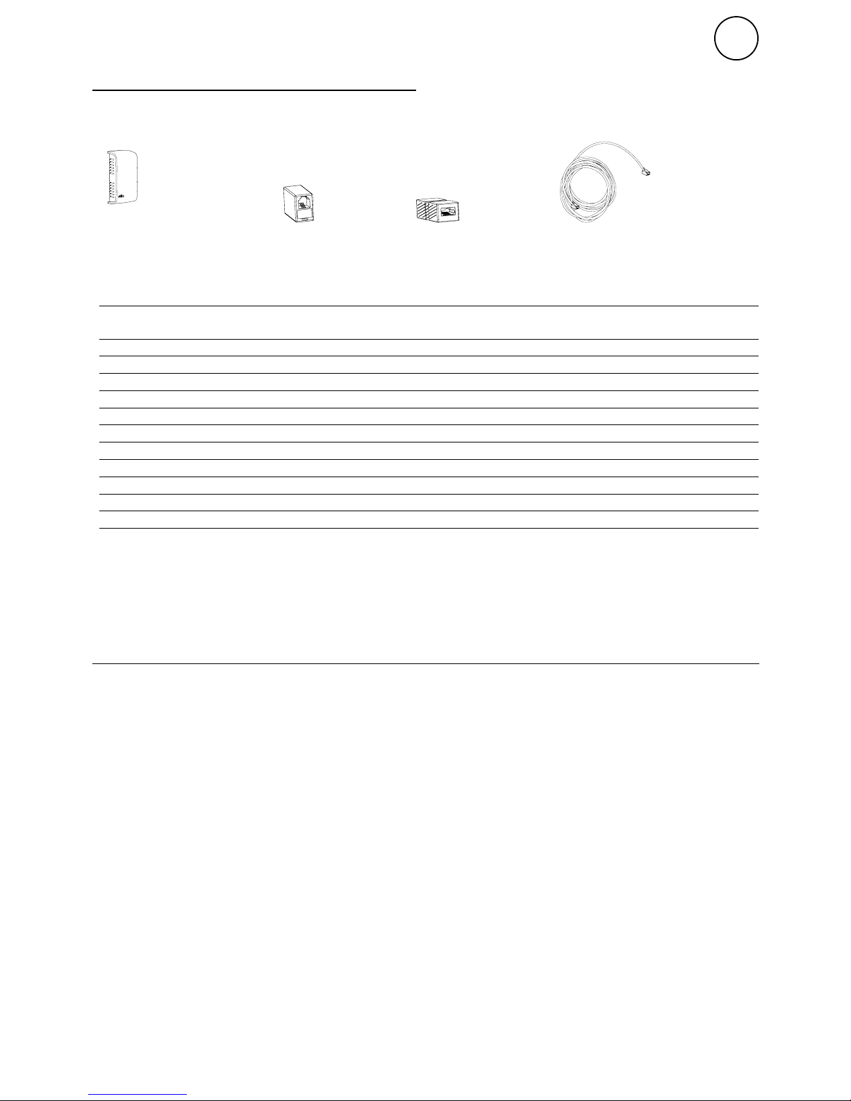
Check that all constituent parts are present
(see section Constituent parts).
Advice about location
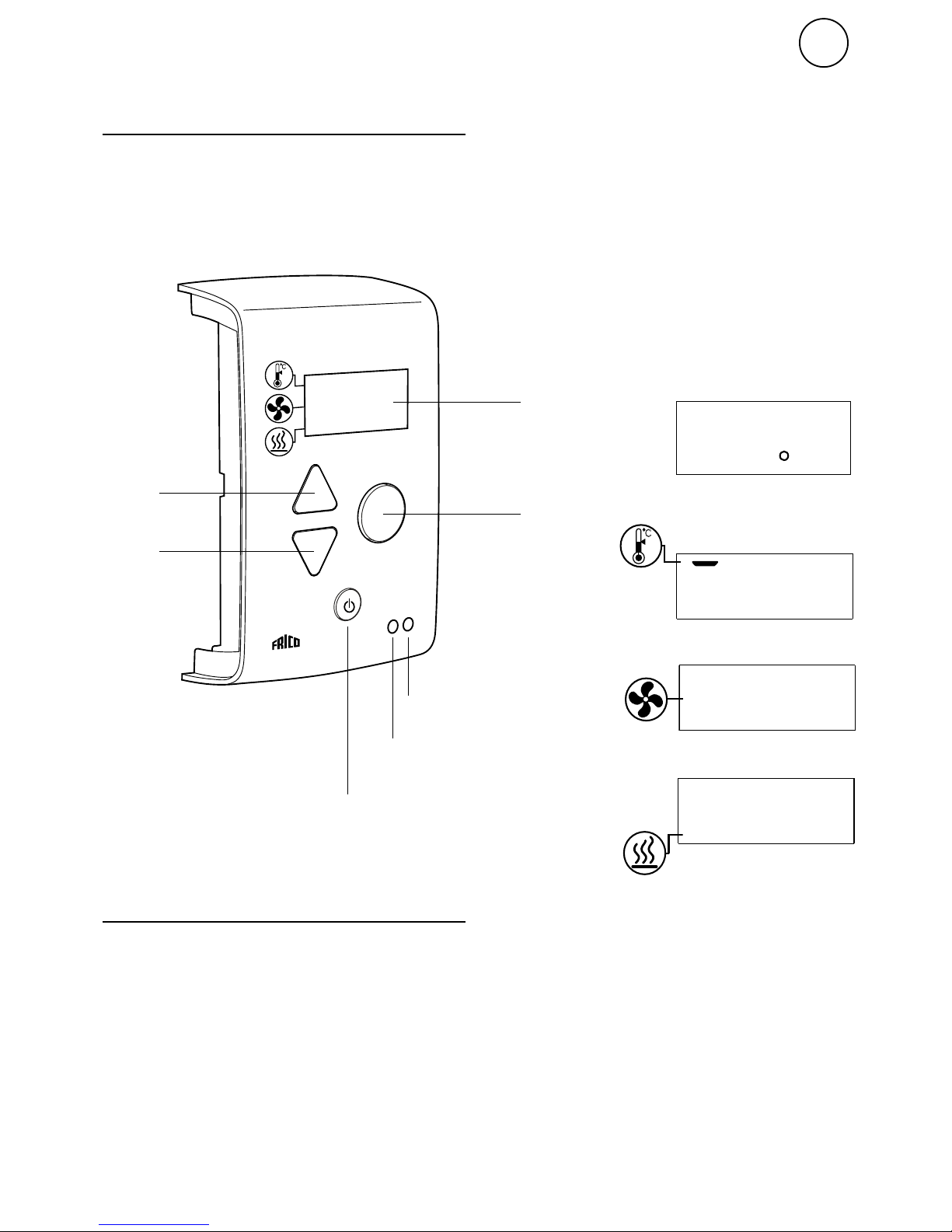
Control unit SIReUB1 has an integrated room
temperature sensor and is installed so that it
is easily accessible to the user.
RJ12 (6p/6c) modular cables, which are
available in different lengths, are used to
connect the PC board and the control unit.
Longer cables are available as options.
Maximum cable lengths see section Options.
To prevent unauthorised people from
accessing the Control unit it can instead
be placed in another area and an external
room sensor, SIReRTX (option), can be
installed in the premises to sense the correct
temperature.
Connect the system
In PC board Base SIReB1(X) the unit is
connected further with RJ12 (6p/6c) modular
cable if several units are to be connected in
parallel. If an external room temperature
sensor SIReRTX is used it is connected using
modular cable RJ11 (4p/4c) on SIReB1(X).
PC board Base SIReB1X in/at the unit and
control unit SIReUB1 is connected with
RJ12 (6p/6c) modular cable when the other
units are powered up. For fixed installation
requirements, remove the supplied cable and
plug. Perform the installation in accordance
with applicable regulations.
Power supply for electric heat must be
connected separately (check manual for the
air curtain unit).
Wiring diagrams
The wiring diagrams are in a separate section
at the end of this manual.
When external PC board Base SIReB1X is
used, wiring between the PC board base and
the air curtain unit must be done. Please see
separate manual for SIReB1X.
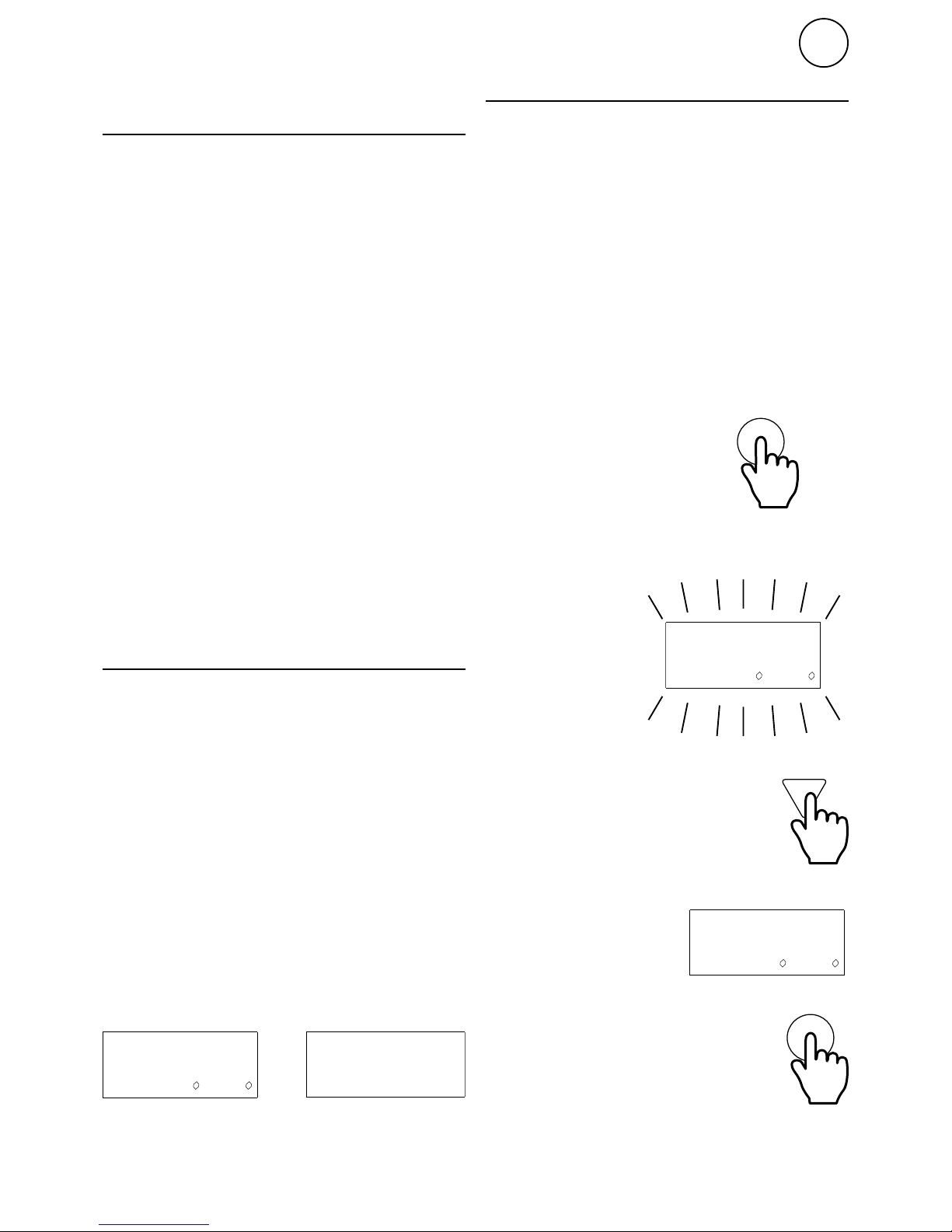
Enter ID/Operation without control unit
The control system can control one or more
units in parallel (max 9). Each unit must get
a unique ID number (1-9) which is set in the
ID selector of the PC board. E.g. Unit 1: ID=1,
unit 2: ID=3
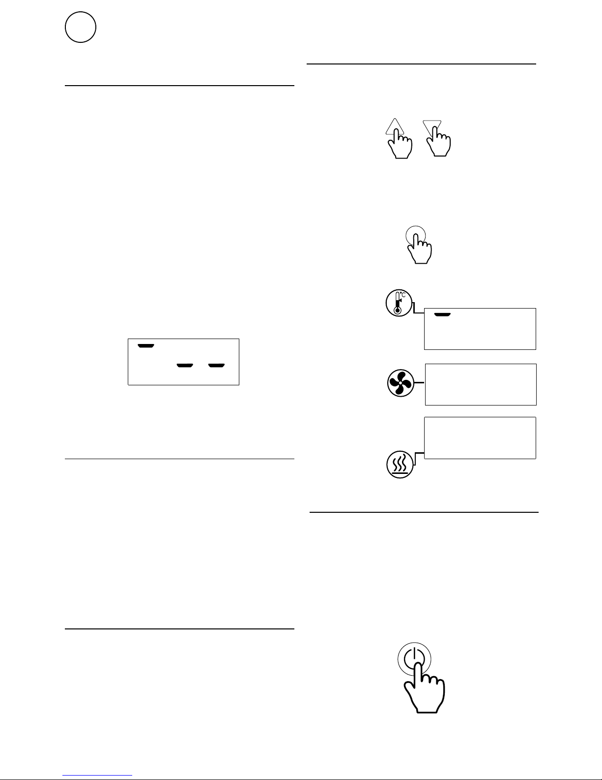
If the external control for some reason has
not been installed the unit can still be run
temporarily. The ID selector is then set to
mode 0 see the image below.
The function is half speed and half heating
output
When the ID number must be changed the
unit must be disconnected from power.
SIRe Basic Air Curtains Electric
11
GB
0
1
2
3