FRIEDHELM LOH Rittal MC3 User manual

Operating instructions
Support rail cutter MC3
4050.437

Foreword
2 We reserve the right to make technical modifications Rittal Support rail cutter MC3
EN Foreword
Dear Customer,
We thank you for choosing our Rittal product. Read these operating instruc-
tions carefully before using your new unit for the first time and retain them to-
gether with the supplied Product Control Card so they can be consulted when
required.
We wish you every success.
Kind regards,
Rittal GmbH & Co. KG
Auf dem Stützelberg
35745 Herborn
Germany
Phone: +49(0)2772 505-0
Fax: +49(0)2772 505-2319
E-mail: info@rittal.com
www.rittal.com
We are always happy to answer any technical questions regarding our entire
range of products.

Contents
Rittal Support rail cutter MC3 We reserve the right to make technical modifications 3
EN
Contents
1Safety instructions ............................................................. 4
1.1 Symbols in these operating instructions .................................................4
1.2 Symbols on the unit ...............................................................................4
1.3 General safety instructions .....................................................................4
1.4 Personal safety equipment .....................................................................5
1.5 Residual risks when using the unit..........................................................5
2Intended use...................................................................... 6
3Technical specifications ..................................................... 6
4Unit description.................................................................. 6
5Assembly and commissioning............................................ 8
6Operation......................................................................... 10
7Maintenance and inspection ............................................ 12
7.1 Maintenance and inspection of the shear plate ....................................12
7.2 General maintenance and inspection ...................................................13
8Dismantling and disposal ................................................. 14
9Contacts.......................................................................... 15

1 Safety instructions
4 We reserve the right to make technical modifications Rittal Support rail cutter MC3
EN 1Safety instructions
1.1 Symbols in these operating instructions
The following symbols are used in this documentation:
Warning!
Hazardous situation which may lead to death or serious
injury if the instructions are not followed.
Caution!
Hazardous situation which may lead to (minor) injuries if the
instructions are not followed.
Note:
Important notes and the identification of situations that can result
in material damage.
This symbol indicates an "action point" and shows that you should perform
an operation or work step.
1.2 Symbols on the unit
The following symbols are attached to the unit.
Risk of being crushed or cut by moving unit components.
Observe the operating instructions.
Wear safety goggles.
Wear protective gloves.
Wear safety shoes.
1.3 General safety instructions
When working with the support rail cutter, improper handling and/or poor
maintenance can damage the unit and cause severe injuries. Consequently,
observe all the following safety instructions and contact our service team
should you have any questions.

1 Safety instructions
Rittal Support rail cutter MC3 We reserve the right to make technical modifications 5
EN
Caution…
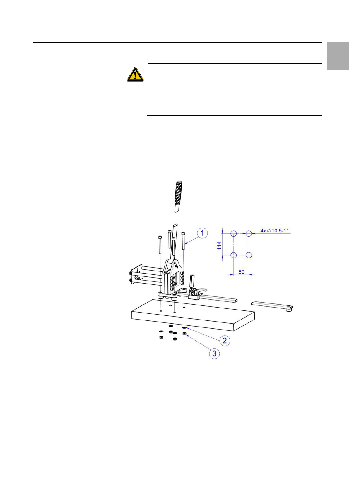
–… The unit may be commissioned only when it is fully mounted permanently
on a sturdy, tip-proof surface. The material for attaching the unit is not in-
cluded. Use a suitable, sturdy fastening material appropriate for the sur-
face.
Always...
–… ensure a stable footing and mount the cutting unit permanently.
–… wear safety goggles, gloves and safety boots when working.
–… remove swarf and other cutting waste from the unit.
–… observe the instructions of these operating instructions.
–… instruct new users in the safe use of the cutting unit.
–… store and deploy in a dry environment.
Never...
–… touch the cutting area of the blade.
–… cut cables with the unit.
–… cut several workpieces concurrently.
–… machine rails made of high-strength steels.
–… deploy the cutting unit when parts are damaged or missing.
–… work with a blunt shear blade.
–… subject the unit to corrosive materials.
–… deploy the unit unless the operating instructions have been read and un-
derstood completely.
1.4 Personal safety equipment
The operating and maintenance personnel must always wear personal protec-
tive equipment when working on the unit. The personal protective equipment
comprises at least the following components:
–Safety shoes: for all work on the unit
–Safety goggles: for all work on the unit
–Gloves: for all work on the unit
1.5 Residual risks when using the unit
There is the danger of being injured by the shear blade when using the unit.
Wear your personal protective equipment for all work performed on the unit
(see section 1.4 "Personal safety equipment") and never place hands and
fingers in the area of the shear blade.

2 Intended use
6 We reserve the right to make technical modifications Rittal Support rail cutter MC3
EN 2Intended use
Mounting angles and support rails made of soft to medium-strength metals
appropriate for the blade geometry can be cut with the “Rittal support rail cut-
ter MC3”. The unit has only limited suitability for processing mounting angles
made of stainless steel. The unit may be deployed only indoors in a dry envi-
ronment.
3Technical specifications
Technical specifications
Model No. and designation
4050.437 support rail cutter MC3
Standard support rails
TS 35/7.5
TS 35/15
C 30 x 15
Support rail material
Medium-strength steel, aluminium, copper
Length of the ruler
100 cm (40.75")
Possible cutting dimensions
4 to 100 cm
Tare weight
14.0 kg (30.8 lbs)
Storage temperature
-30 °C to +60 °C (-22 °F to +140 °F)
Operating temperature
-10 °C to +60 °C (+14 °F to +140 °F)
Tab. 1: Technical specifications
4Unit description
The support rail cutter is a manual cutting unit for mounting angles or support
rails made of metal. The guide plate on the left side exactly positions long
semi-finished products and so improves the cutting quality. The desired
mounting angle length is set precisely and reproducibly using the ruler and the
adjustable end stop. Depending on the profile, the stop flap can be rotated
easily.
The long handle rod and the eccentric level press the shear blade inside the
unit downward, and the workpiece is separated without burrs. Springs press
the shear blade back to its initial position when the level is reset.
The unit stands on four metal feet with through-holes and must also be screw-
fastened by the operator onto the workbench in order to ensure a stable and
tip-proof footing.

4 Unit description
Rittal Support rail cutter MC3 We reserve the right to make technical modifications 7
EN
Fig. 1: Overall view
Legend
1Hand lever
2Eccentric lever
3Front panel with profile opening
4Guide plate
5Metal feet with screw-on points
6Shear plate
7Adjustable limit stop
8Ruler
9Stop flap
Fig. 2: Dimensions in mm
* Possible cutting dimension with limit stop: 40 – 1000 mm

5 Assembly and commissioning
8 We reserve the right to make technical modifications Rittal Support rail cutter MC3
EN 5Assembly and commissioning
You receive all required parts as well as detailed operating instructions.
On receiving the goods, check them for possible transport damage and the
delivery for completeness.
In the event of problems, contact the manufacturer or your vendor without
delay.
In any case, read the complete operating instructions as well as all supplied
documents before commissioning the unit.
Assembly
First screw-in the hand lever into the eccentric lever (fig. 3, item 1) and tight-
en.
Then push the labelled ruler on the shoulder of the base plate and fasten with
the M10x16 bolt and washer (fig. 3, item 5).
Now move the limit stop (fig. 3, item 3) on the ruler, as shown, and click the
individual metal foot (fig. 3, item 4) into the rear opening of the ruler.
The ruler should now be set to the exact dimension.
To do this, set the limit stop with the read-off edge (fig. 3, item 6), e.g. at
118 mm, and measure the distance between the stop flap (fig. 3, item 2) and
the shear plate with a steel scale.
Because the moveable shear plate is 18 mm thick, move the ruler so that a
distance of exactly 100 mm results between the shear plate and the stop
flap.
Tighten the M10x16 bolt (fig. 3, item 5) so that the ruler is positioned exactly.
Fig. 3: Assembly sequence

5 Assembly and commissioning
Rittal Support rail cutter MC3 We reserve the right to make technical modifications 9
EN
Through-holes for four bolts (M10) are provided to attach the support rail cutter
on a sturdy and tip-proof surface.
Caution!
If the support rail cutter is not attached to a sturdy surface,
there is the danger of tipping and so cause injury.
Place the support rail cutter into operation only when it is
completely mounted permanently on a sturdy tip-proof
surface.
First, specify the position of the unit on the surface and accept the fastening
points of the unit.
Fasten the support rail cutter with the following bolts on the surface:
4 x M10 cylinder head bolts, tensile strength 800 N/mm²; the length of the
bolts depends on the thickness of the surface.
Fasten each of the bolts from below with a washer and nut.
Tighten the nuts with a tightening torque of 15 – 20 Nm.
Fig. 4: Support rail cutter attachment

6 Operation
10 We reserve the right to make technical modifications Rittal Support rail cutter MC3
EN 6Operation
After being assembled and attached to a sturdy surface, the support rail cutter
should be operated as follows:
Set the desired length of the support rail at the length stop and fix the posi-
tion using clamping levers.
Fig. 5: Length stop setting
Place the support rail in the appropriate profile of the guide plate and move
through the cutting unit to the limit stop. Ensure there is no jamming and the
free movement of the profile.
Note:
Beforehand, check the support rail for crushed corners and sur-
face coating residues that protrude out of the rail. If possible, re-
move any protruding material so that the support rail can be
moved easily in the cutting unit.
Fig. 6: Support rail insertion
To perform cutting, pull the manual lever downwards and return it upwards
after the cutting operation.

6 Operation
Rittal Support rail cutter MC3 We reserve the right to make technical modifications 11
EN
Fig. 7: Cutting operation
To remove the cut support rail, move the gripping rail backwards fully to its
initial position (fig. 8, item 1).
Depending on the length of the workpiece, it might be necessary to swivel
the stop flap to the side (fig. 8, item 2); then remove the completed profile.
Fig. 8: Support rail removal
Note:
To ensure an optimum cutting result and the correct functioning of
the unit, the shear blade and the eccentric lever must always be
well lubricated.

7 Maintenance and inspection
12 We reserve the right to make technical modifications Rittal Support rail cutter MC3
EN 7Maintenance and inspection
7.1 Maintenance and inspection of the shear plate
The support rail cutter normally requires minimum maintenance and has a long
service life. If, however, impairments occur during operation so that the shear
plate no longer returns to its initial position, this can be caused by inadequate
lubrication or jammed swarf.
Warning!
The profile cut-outs of the shear plate have very sharp edg-
es!
Wear protective gloves for maintenance and cleaning
work.
Also wear safety boots and safety goggles.
To clean the shear plate and the interior of the cutting unit, the following pro-
cedure is possible:
Fold the actuating lever (fig. 9, item 1) completely back.
Loosen the two M8 bolts (fig. 9, item 2) on the lower side of the unit.
Because these bolts pretension the return springs, they must be released al-
ternately in small steps to prevent jamming of the lower plate.
Remove the shear plate from the unit from below (fig. 9, item 3).
If the shear plate is jammed excessively, loosen the eight M10 bolts at the
side by one half turn and press out the shear plate.
Inspect the shear plate for damage and scratches or breakouts at the cutting
edges.
Clean the shear plate thoroughly, remove any adhering swarf and apply uni-
versal grease copiously on all sides.
Clean the interior (fig. 9, item 4) of the cutting unit and purge with com-
pressed air.
Relubricate all surfaces thoroughly with universal grease.
Warning!
When working with compressed air, flying parts or swarf
can cause injuries.
Wear safety goggles.
Ensure no persons are in the vicinity.
When assembling the shear plate, insert the springs in the lower holes of the
shear plate and tighten the lower plate alternately in small steps with the two
M10x25 bolts.
If necessary, also retighten the eight bolts at the side.
Torque for these M10 bolts, each 20-30 Nm.
Check the correct functioning and the smooth-action.

7 Maintenance and inspection
Rittal Support rail cutter MC3 We reserve the right to make technical modifications 13
EN
Fig. 9: Shear plate maintenance
7.2 General maintenance and inspection
The user is obliged to maintain and service the cutting unit in accordance with
the details in the operating instructions, and in accordance with country-
specific standards and regulations.
The maintenance intervals are classified in accordance with the recommended
frequency:
Before each use…
… visually inspect the cutting unit for damage.
… clean the profile openings.
Weekly…
… check the correct functioning of the operating lever and of the shear
blade.
… clean the contact surface and profile openings with compressed air.
… check the sturdy bearings of the stop flap.
… check the sturdy footing of the unit on the workbench.
Monthly…
… check the markings and the labels for readability and damage, and re-
place if necessary.
… coat the running surface of the eccentric lever with copious universal
grease.
… lightly grease with a brush and corrosion protection oil the blade and the
cutting unit to protect against corrosion.
… check the sharpness of the shear blade and, if necessary, replace the
blade. Increased formation of burrs on the profile is a sign of wear on the
shear plate.

8 Dismantling and disposal
14 We reserve the right to make technical modifications Rittal Support rail cutter MC3
EN
Note:
Use only original spare parts
8Dismantling and disposal
Wear your personal protective equipment, in particular gloves and safety
shoes, also for the dismantling and disposal of the unit (see section 1.4
"Personal safety equipment").
The support rail cutter must be disposed of or recycled appropriately in ac-
cordance with the country-specific regulations.

9 Contacts
Rittal Support rail cutter MC3 We reserve the right to make technical modifications 15
EN
9Contacts
For technical queries, please contact:
–Phone: +49(0)2772 505-9052
–E-mail: info@rittal.com
–Homepage: www.rittal.com
For sales or service requests, please contact your local Rittal organisation
which can be found at www.rittal.com/contact.

You can find the contact details of all
Rittal companies throughout the world here.
www.rittal.com/contact
RITTAL GmbH & Co.
KG
Auf dem Stuetzelberg · 35745 Herborn · Germany
Phone +49 2772 505
-0
E-mail: info@rittal.de · www.rittal.com
08.2020 / D-0100-00000215-01-EN
◾
Enclosures
◾
Power Distribution
◾
Climate Control
◾
IT Infrastructure
◾
Software & Services
This manual suits for next models
2
Table of contents