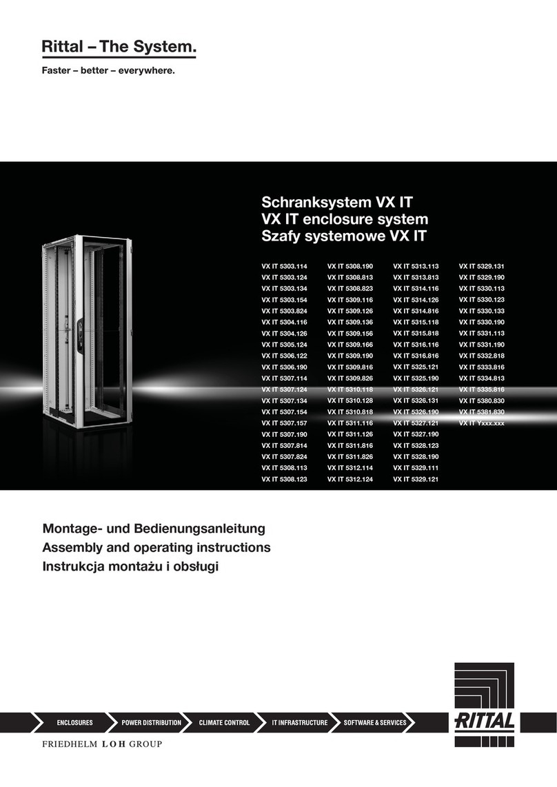
FRIEDHELM LOH RITTAL 7888.390 User manual

Montage- und Bedienungsanleitung
Assembly and operating instructions
Notice de montage et d’emploi
Netzwerkschrank TE 8000
Verteilerrahmen TE 8000 open
Network enclosures TE 8000
Distributor racks TE 8000 open
Baies réseaux TE 8000
Ossature de répartiteur TE 8000 open
7888.390
7888.410
7888.430
7888.440
7888.500
7888.510
7888.460
7888.520
7888.530
7888.532
7888.840
7888.850
7888.875
7888.882
7888.892
7888.940
7888.944

2 TE 8000 Montageanleitung/TE 8000 assembly instructions/TE 8000 – Notice de montage
Lieferumfang 4
Technische Daten 5
Hinweise zur Dokumentation
– Verwendete Symbole 5
Sicherheitshinweise 6 – 7
Bestimmungsgemäße Verwendung und
Einschränkung 7
Montage
– Niveauregulierung 8
– Tiefenverstellung der Ebenen 8
– Aktivierung der Kabeleinführung 8
– Montage Rollen 9
– Montage Sockel VX 10
– Bodenbefestigung 11
– Passive und aktive Belüftung 12
– Montage Kabeltrasse 13
– Montage Seitenwand 14
– Türanschlag wechseln
für Tür mit Grischale 15
– Demontage Grischale 16
– Montage Ergoform-S-Schwenkhebel
für Profilhalbzylinder 16
– Einsatz Verschlussstange 16
– Austausch Logo 16
– Türanschlagwechsel mit
Ergoform-S-Schwenkhebelgri 17 – 18
– Erdung und Potenzialausgleich 19
– Innenausbau-Möglichkeiten 20 – 21
Garantie 22
Kundendienstadressen 22
Scope of supply 4
Technical data 5
Notes on documentation
– Symbols used 5
Safety notes 6 – 7
Intended use and limitation 7
Assembly
– Level control 8
– Depth adjustment of the levels 8
– Activation of cable entry 8
– Fitting the castors 9
– Fitting the VX base/plinth 10
– Base mounting 11
– Passive and active ventilation 12
– Fitting the cable route 13
– Fitting the side panels 14
– Switching the door hinges
for a door with moulded handle 15
– Removing the moulded handle 16
– Installing the Ergoform-S
swing lever handle for semi-cylinder 16
– Inserting the locking bar 16
– Replacing the logo 16
– Switching the door hinges with
Ergoform-S swing lever handle 17 – 18
– Earthing and potential equalisation 19
– Interior installation options 20 – 21
Warranty 22
Customer service addresses 22
Composition de la livraison 4
Caractéristiques techniques 5
Remarques relatives à la documentation
– Symboles utilisés 5
Consignes de sécurité 6 – 7
Utilisation correcte de l’appareil et
restrictions 7
Montage
– Réglage à niveau 8
– Réglage en profondeur des
plans de montage 8
– Ouverture des passages de câbles 8
– Montage des roulettes 9
– Montage du socle VX 10
– Fixation au sol 11
– Ventilation passive et active 12
– Montage du chemin de câbles 13
– Montage des panneaux latéraux 14
– Changement du sens d’ouverture
pour porte avec poignée coquille 15
– Démontage de la poignée coquille 16
– Montage de la poignée
pivotante Ergoform-S pour
serrure semi-cylindrique 16
– Montage de la crémone 16
– Remplacement du logo 16
– Changement du sens d’ouverture
pour porte avec poignée pivotante
Ergoform-S 17 – 18
– Mise à la terre et équipotentialité 19
– Possibilités d’équipement
intérieur 20 – 21
Garantie 22
Adresses des services après-vente 22
Inhaltsverzeichnis/Contents/Sommaire

3TE 8000 Montageanleitung/TE 8000 assembly instructions/TE 8000 – Notice de montage
Inhaltsverzeichnis/Contents/Sommaire
4–7,
22 8 101112
12 14 15 19
91316
17–18 20–21
Inhaltsverzeichnis/Contents/Sommaire

4 TE 8000 Montageanleitung/TE 8000 assembly instructions/TE 8000 – Notice de montage
max. 400 kg max. 400 kg max. 700 kg max. 700 kg
Breite/Width/Largeur mm 600 800 800 600 800 600 800
Best.-Nr. TE
Model No. TE
Référence TE
7888.390
7888.410
7888.430
7888.440
7888.500
7888.510
7888.460
7888.520
7888.530
7888.532
7888.840
7888.850 7888.875
7888.882 7888.892 7888.940 7888.944
DK 7888.610
DK 7888.612 – – 2 x – – 1 x 2 x
4 x 4 x 4 x 4 x 4 x 4 x 4 x
M10 4 x 4 x – 4 x 4 x 4 x 4 x
2 x 2 x 2 x 2 x – – –
nicht bei
not with
sauf pour
7888.532
nur bei
only with
uniquement
sur
7888.875
SZ 4943.000 – – 6 x – – – –
DK 7111.000 – – 10 x – – – –
EL 2094.500 M5 – – 50 x – – – –
DK 7094.130 M5 x 16 – – 50 x – – – –
PS 4612.000 M12 – – 4 x – – – –
VX 8100.770 – – 1 x – – – –
VX 8620.003 – – 2 x – – – –
VX 8620.091 – – 2 x – – – –
TE 7888.640 –
nur bei
only with
uniquement
sur
7888.532
– 4 x 4 x – –
Lieferumfang/Scope of supply/Composition de la livraison

5TE 8000 Montageanleitung/TE 8000 assembly instructions/TE 8000 – Notice de montage
Hinweise zur Dokumentation/Notes on documentation/
Remarques relatives à la documentation
Die Montageanleitung richtet sich an alle
Personen, die über eine entsprechende
Fachausbildung verfügen, um Schaltschränke
normgerecht mit elektrischen, elektronischen,
mechanischen und pneumatischen Betriebs-
mitteln auszurüsten bzw. zu montieren und
betriebsfertig anzuschließen.
Diese Anleitung richtet sich an das Bedien-
personal und entsprechend ausgebildete
Fachkräfte für elektronische und mechanische
Instandhaltung.
The assembly instructions are aimed at
personnel who have completed correspond-
ing technical training and are thus qualified to
set up enclosures with electrical, electronic,
mechanical and pneumatic equipment in
accordance with applicable standards and to
erect, assemble and connect such enclosures
at the place of use.
These instructions are aimed at operating
personnel and correspondingly trained
specialists for electrical and mechanical
maintenance.
La notice de montage s’adresse à toutes
les personnes qui possèdent la formation
technique susante pour le montage, l’instal-
lation sur site et le raccordement d’armoires
électriques selon les normes électriques,
électroniques, mécaniques et pneumatiques
en vigueur.
Cette notice s’adresse aux opérateurs et
aux spécialistes formés pour la maintenance
électrotechnique.
Technische Daten
Temperatureinsatzbereich:
+15 °C bis +45 °C
Lagerungstemperatur:
-20 °C bis +80 °C
Technical data
Operating temperature range:
+15 °C to +45 °C
Storage temperature:
-20 °C to +80 °C
Caractéristiques techniques
Plage de température de fonctionnement :
+15 °C à +45 °C
Plage de température de stockage :
-20 °C à +80 °C
Verwendete Symbole
Beachten Sie folgende Sicherheits- und sons-
tige Hinweise in der Anleitung:
Symbol für eine Handlungsanweisung:
䡲Der Blickfangpunkt zeigt an, dass Sie eine
Handlung durchführen sollen.
Sicherheits- und andere Hinweise:
Gefahr!
Unmittelbare Gefahr für Leib
und Leben.
Achtung!
Mögliche Gefahr für Produkt
und Umwelt.
Hinweis:
Nützliche Information und
Besonderheiten.
Symbols used
Observe the following safety and other notes
in the instructions:
Symbol identifying required actions:
䡲The bullet point indicates an action to be
performed.
Safety and other notes:
Danger!
Immediate danger to life and
limb.
Caution!
Potential threat to the product
and its environment.
Note:
Useful information and special
features.
Symboles utilisés
Tenir compte des consignes de sécurité et
autres directives contenues dans cette notice :
Symbole indiquant une action à eectuer :
䡲Le pictogramme en caractère gras indique
que vous devez exécuter une action.
Consignes de sécurité et
autres directives :
Danger !
Risque de blessure grave, voire
mortelle.
Attention !
Danger éventuel pour le produit
et l’environnement.
Remarque :
informations utiles
et particularités.
Technische Daten/Technical data/Caractéristiques techniques

6 TE 8000 Montageanleitung/TE 8000 assembly instructions/TE 8000 – Notice de montage
Sicherheitshinweise/Safety notes
Gefahr!
Unmittelbare Gefahr für Leib
und Leben.
Entpacken und bewegen
䡲Achtung, das TE 8000 Rack ist kopflastig
und kann umkippen. Beim Bewegen und
Auspacken des Racks werden mindestens
2 Personen benötigt.
䡲Bei Nichtbeachtung dieser Vorschrift kann
es zu folgenschweren Verletzungen
und/oder zu Sachschäden kommen.
Betriebsumgebung
䡲Achtung, das TE 8000 Rack ist nur für die
sachgerechte Anwendung im Innenbereich
und in geschützter Umgebung bestimmt;
nicht im Außenbereich, in rauer Umgebung
oder in Belüftungsbereichen verwenden.
䡲Bitte beachten Sie hierzu auch die Herstel-
lerangaben der zu verbauenden Kompo-
nenten. Es sind besonders die zulässigen
Umgebungsparameter wie Temperatur,
Luftfeuchtigkeit (keine Betauung) und die
Anforderungen an die Umgebungsluft zu
berücksichtigen.
䡲Achtung, das TE 8000 Rack muss, bei
Installation mit oenen oder teilweise
geöneten, elektrischen Komponenten und
einer leicht entflammbaren Oberfläche am
Aufstellungsort, zusätzlich von unten mit
Bodenblechen verschlossen sein.
482.6 mm (19˝)-Verstellung
䡲Achtung, Gefahr durch herabfallende
Geräte. Beim Verstellen der Profilschienen
dürfen keine Geräte auf diesen eingebaut
sein.
䡲Die 19˝-Ebene des TE 8000 bildet ein
gehäusestabilisierendes Element, daher darf
jede Ebene nur separat voneinander gelöst
und verschoben werden. Erst wenn eine
Ebene wieder sicher verschraubt ist, darf
eine andere gelöst und verschoben werden.
䡲Bei Nichtbeachtung kann es zu schweren
Verletzungen und/oder zu Schäden an
Geräten kommen.
Rackstabilisierung
䡲Je nach Aufstellungsort und/oder Rack-
Konfiguration sind Stabilisierungsmaß-
nahmen empfehlenswert bzw. erforderlich.
Rackbestückung
䡲Die Installation der Geräte muss den
jeweiligen Bestimmungen für die Installation
von elektrischen Geräten und Geräten der
Datenverarbeitungstechnik entsprechen.
䡲Die Installation darf nur von geschultem
Fachpersonal mit entsprechender Zulassung
durchgeführt werden.
䡲Bevor Sie das TE 8000 Rack bestücken,
sollten Sie die Platzierung aller Komponen-
ten festlegen. Die Faktoren der jeweiligen
Komponenten, wie Gewicht, Erreichbarkeit
sowie Anforderungen an Stromversorgung,
Temperatur und Luftzirkulation, haben einen
Einfluss auf die Reihenfolge und den Ort,
an dem Sie die Komponenten im Rack
platzieren.
Platzieren Sie die schwersten Komponen-
ten stets unten im TE 8000 Rack. Dadurch
erhöhen Sie die Standsicherheit.
䡲Für Bauteile oder Komponenten, die mehr
als 22,5 kg wiegen, werden für die Montage
und Demontage mindestens zwei Personen
benötigt.
䡲Es ist stets auf eine ordnungsgemäße Befes-
tigung bzw. auf eine gesicherte Lage aller
Komponenten und Rack-Bauteile zu achten.
䡲Vor der Inbetriebnahme müssen die
TE 8000 Racks mit geeigneten Seitenwän-
den verschlossen werden.
Vorsicht bei Auszugskomponenten und
Gerätebodenauszug
䡲Zur Vermeidung von Verletzungen oder
Sachschäden müssen Sie das TE 8000
Rack angemessen stabilisieren, bevor Sie
eine Komponente oder einen Geräteboden
aus dem Rack herausziehen.
䡲Ziehen Sie immer nur eine Komponente/
einen Geräteboden heraus. Das Rack kann
instabil werden, wenn mehrere Komponen-
ten gleichzeitig herausgezogen werden.
Danger!
Immediate danger to life
and limb.
Unpacking and moving
䡲Attention: The TE 8000 rack is top-heavy
and can tilt over. At least two persons are
required when moving or unpacking the
rack.
䡲Failure to observe this rule may lead to seri-
ous injuries and/or material damage.
Operating environment
䡲Attention: The TE 8000 rack is exclusively
designed for indoor use and protected
environments; do not use outdoors, in harsh
environments or air-handling spaces.
䡲Also observe the information provided by
the manufacturer(s) of the components to be
installed. Particular attention must be paid to
the permissible environmental parameters,
such as temperature and humidity (non-
condensing), and to the demands placed on
the ambient air.
䡲Attention: In case of installations with
exposed or partially exposed electrical
components located near an inflammable
surface, the TE 8000 rack must also be
sealed in the base with gland plates.
482.6 mm (19") level adjustments
䡲Attention: Hazards due to falling devices and
equipment. If the mounting levels are to be
adjusted, no devices or equipment must be
installed on the levels concerned.
䡲Because the 19" level of the TE 8000 is an
element that serves to stabilise the housing,
each level may be released and moved only
separately from each other. Only when one
level has been securely fastened again, may
another level be released and moved.
䡲Failure to observe this rule may lead to seri-
ous injuries and/or damage to the devices or
equipment.
Rack stabilisation
䡲Stabilisation measures are recommended or
even imperative, depending on the place of
installation and/or the rack configuration.
Rack configuration
䡲The installation of devices and equipment
must comply with the applicable regulations
pertaining to the installation of electrical and
data processing devices and equipment.
䡲Installation work must only be performed by
trained expert personnel holding corre-
sponding certificates of qualification.
䡲Determine the positions of the individual
components before starting the actual
configuration of the TE 8000 rack. Factors
such as weight, accessibility, power supply
requirements, temperature and air circulation
influence the order of installation and the
positioning of the individual components in
the rack.
The heaviest components should always be
installed in the bottom of the TE 8000 rack,
as that increases the stability of the rack.
䡲At least two persons are required to install
or remove equipment or components which
weigh more than 22.5 kg.
䡲Always ensure proper fixing and safe place-
ment of all components and rack elements.
䡲TE 8000 racks must always be closed with
appropriate side panels prior to commis-
sioning.
Caution in case of withdrawable
components and component shelves
䡲To avoid injuries or material damage, the
TE 8000 rack must be stabilised appropri-
ately before pulling out any withdrawable
components or component shelves.
䡲Always pull only one component or com-
ponent shelf out at a time. The rack may
become unstable if several components are
pulled out at once.
7TE 8000 Montageanleitung/TE 8000 assembly instructions/TE 8000 – Notice de montage
Consignes de sécurité
Danger !
Risque de blessure grave,
voire mortelle.
Déballage et transport
䡲Attention, la baie TE 8000 est lourde à
l’avant et peut basculer. Deux personnes, au
minimum, sont nécessaires pour le transport
et le déballage de la baie.
䡲Le non-respect de cette consigne peut
entraîner des blessures conséquentes et/ou
des dommages matériels.
Milieu ambiant
䡲Attention, la baie TE 8000 est exclusivement
destinée à une mise en œuvre dans des
environnements protégés et en intérieur ; ne
pas l’utiliser en extérieur dans des environ-
nements sévères.
䡲Veuillez également respecter les indications
du fabricant pour les composants à intégrer.
Il faut, en particulier, tenir compte des para-
mètres ambiants comme la température,
l’humidité de l’air (sans condensation) et les
exigences vis à vis de l’air ambiant.
䡲Attention, dans le cas de l’installation
d’équipements électriques ouverts ou
partiellement ouverts sur un site où certaines
surfaces sont facilement inflammables,
alors la baie TE 8000 doit être équipée de
plaques passe-câbles étanches.
Réglage 19"
䡲Attention, risque dû aux appareils qui
chutent. Aucun appareil ne doit être installé
sur les montants 19" lors du réglage de
ceux-ci.
䡲Le plan de montage 19" de la baie TE 8000
forme un élément qui rigidifie l’ossature, ce
qui fait que chaque plan de montage doit
être desserré et déplacé indépendamment
l’un de l’autre. Vous pouvez desserrer et
déplacer un nouveau plan de montage
uniquement après avoir solidement vissé la
précédente.
䡲Le non-respect peut entraîner des bles-
sures graves et/ou des dommages sur les
appareils.
Stabilisation des baies
䡲Des mesures de stabilisation sont conseil-
lées ou nécessaires en fonction du lieu
d’implantation et/ou de la configuration de
la baie.
Équipement des baies
䡲L’installation des appareils doit correspondre
aux diérentes règles pour l’installation
d’appareils électriques et d’appareils de
traitement des données.
䡲L’installation doit être eectuée uniquement
par du personnel formé et qualifié qui pos-
sède l’habilitation requise.
䡲L’implantation de tous les composants
devrait être définie avant d’équiper la baie
TE 8000. Les facteurs des diérents compo-
sants comme la masse, l’accessibilité ainsi
que les besoins d’alimentation électrique, de
température et de circulation d’air ont une
influence sur l’ordre et le lieu d’implantation
des composants dans la baie.
Placer toujours les composants les plus
lourds dans le bas de la baie TE 8000. Cela
augmente la stabilité.
䡲Le montage et le démontage des équipe-
ments ou des composants d’une masse
supérieure à 22,5 kg nécessitent au moins
deux personnes.
䡲Il faut toujours veiller à une fixation conforme
ou à une implantation fiable de tous les
composants et équipements de la baie.
䡲Les baies TE 8000 doivent toujours être
obturées par des panneaux latéraux appro-
priés avant leur mise en service.
Prudence avec les composants et les
tablettes d’appareillage extensibles
䡲Pour éviter les blessures ou les dommages
matériels, il faut stabiliser convenablement la
baie TE 8000 avant de sortir un composant
ou une tablette d’appareillage de la baie.
䡲Sortir toujours un seul composant ou une
seule tablette d’appareillage. La baie peut
devenir instable lors de la sortie simultanée
de plusieurs composants.
Bestimmungsgemäße Verwendung und Einschränkung/Intended use and
limitation/Utilisation correcte de l’appareil et restrictions
Bestimmungsgemäße Verwendung
Aufnahme von Geräten/Anwendungen nach
EN 60950, DIN EN 62368:
Rittal IT-Gehäuse dienen der Aufnahme und
dem Betrieb elektrischer Einrichtungen der
Telekomunikations- und Informationstechnik
inkl. der hierfür notwendigen Verkabelung. Die
aufzunehmenden Komponenten entsprechen
in der Regel elektronischen Komponenten
nach dem Standard IEC 60297-1/2 oder der
ETS 300 119-3.
Einschränkung, Grenzen der erlaubten
Verwendung
Nicht vorgesehen ist die Verwendung als
Brandschutzgehäuse und der Einbau von
Niederspannungsschaltgerätekombinationen
im Sinne der IEC 61439, die Herstellung eines
Berührungsschutzes bezüglich eingebauter
Komponenten oder die Aufnahme von elekt-
risch nicht sicheren Komponenten.
Die in der Anleitung genannten Hinweise zur
Bestückung des Gehäuses, insbesondere zur
Standsicherheit, sind zu beachten.
Intended use
Accommodation of equipment/applications in
accordance with EN 60950, DIN EN 62368:
Rittal IT enclosures serve to accommodate
and permit the operation of electrical tel-
ecommunication and information technology
equipment, including the necessary wiring
for such equipment. The components to be
accommodated generally represent electronic
components in accordance with the standards
IEC 60297-1/2 or ETS 300 119-3.
Limitation of the permitted use
The following are deemed use other than
as intended: Use as fire protection enclosure;
installation of low-voltage switchgear and
controlgear assemblies in the sense of IEC
61439; use to provide shock hazard protec-
tion in respect of contact with the installed
components; accommodation of electrically
unsafe components.
The notes given in the user manual regarding
component installation, and in particular the
stability of the enclosure, must be observed.
Utilisation correcte de l’appareil
Intégration d’appareils / exploitations selon la
norme EN 60950, EN 62368 :
les baies IT Rittal servent à intégrer et à
exploiter des dispositifs électriques du secteur
des télécommunications et de l’informatique
y compris le câblage nécessaire pour cela.
Les composants à intégrer sont conformes au
règlement pour les composants électroniques
selon le standard CEI 60297-1/2 ou ETS 300
119-3.
Restrictions, limites de l’utilisation
autorisée
N’est pas prévue l’utilisation comme armoire
de protection contre l’incendie, l’intégration de
TGBT selon la norme CEI 61439, la réalisation
d’une protection contre les contacts acciden-
tels de composants intégrés ou l’intégration
de composants électriques sans sécurité
intrinsèque.
Les indications pour l’équipement de la baie
qui figurent dans la notice, en particulier pour
la stabilité, doivent être respectées.

8 TE 8000 Montageanleitung/TE 8000 assembly instructions/TE 8000 – Notice de montage
1
2
2
2
2
2
2
3
2
2
1
1
1
2.1
2.2
2.3
MA= 10 Nm
3.23.1
Niveauregulierung, Tiefenverstellung der
Ebenen und Aktivierung der Kabeleinführung
Level control, depth adjustment of the levels,
and activation of cable entry
Réglage à niveau, réglage en profondeur des
plans de montage et ouverture des passages
de câbles
TX30mm SW10
Zur Tiefenverstellung jeweils nur eine
Ebene ( A/ B) lösen!
For depth adjustment, only release
one level ( A/ B)!
Pour le réglage en profondeur,
ne sélectionner qu’un seul plan de
montage ( A/ B) à la fois !
SW8
1
max. 7 mm
8x (M6 x 12)
4x (M10)
A
B
B/W/L = 600 / DK 7888.610 B = 800 / DK 7888.612

9TE 8000 Montageanleitung/TE 8000 assembly instructions/TE 8000 – Notice de montage
1
1
1
1
Montage Rollen
Fitting the castors
Montage des roulettes
SW8/17
1 1
TE 7000.672
4x (M10)

10 TE 8000 Montageanleitung/TE 8000 assembly instructions/TE 8000 – Notice de montage
1.1
1.2
2.1
3
Montage Sockel VX
Fitting the VX base/plinth
Montage du socle VX
1
1
1
1
2
2
22
SW8
TS 8100.XXX
TS 8200.XXX
2.2
MA= 6 Nm
optional
3
3
3
3
1.3
MA= 20 Nm

11TE 8000 Montageanleitung/TE 8000 assembly instructions/TE 8000 – Notice de montage
1
Bodenbefestigung
Base mounting
Fixation au sol
SW8ø 12
1
1
1
1
SO 2817.000

12 TE 8000 Montageanleitung/TE 8000 assembly instructions/TE 8000 – Notice de montage
Passive und aktive Belüftung
Passive and active ventilation
Ventilation passive et active
1
2
1.1
2.1
1.2
MA= 1 Nm
TX25SW7
DK 5502.020
4x (M6 x 12)
4x
2.2
DK 5502.020
B = 600 mm

13TE 8000 Montageanleitung/TE 8000 assembly instructions/TE 8000 – Notice de montage
Montage Kabeltrasse
Fitting the cable route
Montage du chemin de câbles
1
MA= 5 Nm
1
MA= 5 Nm
PZ
1
1
1
2
DK 7000.685
6x (5.5 x 13)
6x (5.5 x 13)
R
R

14 TE 8000 Montageanleitung/TE 8000 assembly instructions/TE 8000 – Notice de montage
1
1
2
2
3
3
3
3
1
2
3.1 3.2
Montage Seitenwand
Fitting the side panels
Montage des panneaux latéraux

15TE 8000 Montageanleitung/TE 8000 assembly instructions/TE 8000 – Notice de montage
12
34
7
9
6
8
7
5
1
2
3
4
TX30
6
MA= 5 Nm
1x (M5 x 12)
5
MA= 5 Nm
1x (M5 x 12)
Türanschlagwechsel
für Tür mit Grischale
Switching the door hinges for a
door with moulded handle
Changement du sens
d’ouverture pour porte avec
poignée coquille
8
1x (M5 x 12)
MA= 5 Nm
9
1x (M5 x 12)
MA= 5 Nm
Die Verschlussgegenstücke werden beim Türanschlag-
wechsel auf der gegenüberliegenden Seite montiert.
When the door hinges are switched, the lock
counterparts are mounted on the opposite side.
Les butées de porte sont montées du côté opposé lors
du changement du sens d’ouverture de la porte.

16 TE 8000 Montageanleitung/TE 8000 assembly instructions/TE 8000 – Notice de montage
1
2
1
PZ
1x (M5 x 25)
1x (M4 x 6)
2.1
MA= 2 Nm
1x (M5 x 25)
1x (M4 x 6)
2.2
SZ 2435.000
Demontage Grischale, Montage Ergoform-S-
Schwenkhebelgri für Profilhalbzylinder,
Einsatz Verschlussstange, Austausch Logo
Removing the moulded handle, installing the
Ergoform-S swing lever handle for semi-cylin-
der, inserting the locking bar, replacing the logo
Démontage de la poignée coquille, montage de
la poignée pivotante Ergoform-S pour serrure
semi-cylindrique, montage de la crémone,
remplacement du logo

17TE 8000 Montageanleitung/TE 8000 assembly instructions/TE 8000 – Notice de montage
PZ
SZ 2435.000
Türanschlagwechsel mit
Ergoform-S-Schwenkhebelgri
Switching the door hinges with
Ergoform-S swing lever handle
Changement du sens d’ouverture pour porte
avec poignée pivotante Ergoform-S
1 8
2 9
3 10
4
6
5
7
6
4
5
7
8.2
1
8.1
8.3
3
9
2
10
Stange in geönetem Zustand in Höhe der oberen und
unteren Befestigung markieren.
With the door open, make marks on the rod at the
height of the top and bottom attachments.
Marquer la tringlerie en position ouverte dans la hau-
teur de la fixation inférieure et supérieure.

18 TE 8000 Montageanleitung/TE 8000 assembly instructions/TE 8000 – Notice de montage
PZ
SZ 2435.000
Türanschlagwechsel mit
Ergoform-S-Schwenkhebelgri
Switching the door hinges with
Ergoform-S swing lever handle
Changement du sens d’ouverture pour porte
avec poignée pivotante Ergoform-S
18
20
1215
1316
21
1117
19
12
14
13
15
16
11.1 11.2
17
1x (M5 x 25)
1x (M4 x 6)
MA= 2 Nm
20
MA= 5 Nm
2x (M5 x 12)
18
2x (M5 x 12)
MA= 5 Nm
21
MA= 5 Nm
1x (M5 x 12)
2219
1x (M5 x 12)
MA= 5 Nm
22

19TE 8000 Montageanleitung/TE 8000 assembly instructions/TE 8000 – Notice de montage
5
6 1
2
1
3
4
2
2
3
5
4
6
1
Erdung und Potenzialausgleich
Earthing and
potential equalisation
Mise à la terre et
équipotentialité
optional

20 TE 8000 Montageanleitung/TE 8000 assembly instructions/TE 8000 – Notice de montage
Innenausbau-Möglichkeiten
Interior installation options
Possibilités d’équipement intérieur
A
B
C
D
E
H
I
J
K
L
F
G
TX25
Ebenenabstand mm
Distance between levels mm
Écartement entre les plans 19" mm
Länge/Befestigungsmaß mm
Length/mounting dimension mm
Longueur / cote de fixation mm
Für Breite/Tiefe mm
For width/depth mm
Pour largeur / profondeur mm
VE (St.)
Packs of
UE (p.)
Best.-Nr.
Model No.
Référence
A495 455/375 600/800 6 SZ 4943.000
B
395 324/275 600 2 DK 7963.310
495 424/375 600/800 2 DK 7963.410
595 524/475 800/1000 2 DK 7963.510
695 624/575 1000 2 DK 7963.610
C495 –/375 600/800 4 DK 7828.040
D495 390/375 600/800 20 TS 4309.000
E495 –/375 600/800 4 TS 8612.040
F495 416/375 600/800 1 TE 7000.620
G495 500/375 600/800 1 DK 7000.625
H495 –/375 600/800 4 DK 7858.160
745 –/625 1000 4 DK 7858.162
I450 – 800 450 – 800 600/800/1000 1 DK 7016.140
450 – 800 450 – 800 600/800/1000 1 DK 7016.150
J745 –/625 1000 2 DK 7000.678
745 740/– 1000 2 DK 7063.740
K400 – 600 – 600/800 2 DK 5501.460
600 – 900 – 800/1000 2 DK 5501.480
L390 – 550 – 600/800 2 DK 7063.750
550 – 750 – 1000 2 DK 7063.752
This manual suits for next models
16
Table of contents
Other FRIEDHELM LOH Enclosure manuals

FRIEDHELM LOH
FRIEDHELM LOH Rittal SK 3185330 User manual

FRIEDHELM LOH
FRIEDHELM LOH RITTAL HD 1302.600 User manual

FRIEDHELM LOH
FRIEDHELM LOH RITTAL KX 1500.000 User manual

FRIEDHELM LOH
FRIEDHELM LOH RITTAL VX25-SV User manual

FRIEDHELM LOH
FRIEDHELM LOH Rittal 8618.600 User manual

FRIEDHELM LOH
FRIEDHELM LOH Rittal VX IT Series User manual

FRIEDHELM LOH
FRIEDHELM LOH RITTAL TopConsole TP 6700.600 User manual

FRIEDHELM LOH
FRIEDHELM LOH Rittal AX 1485.744 User manual

FRIEDHELM LOH
FRIEDHELM LOH Rittal FT 2740.010 User manual

FRIEDHELM LOH
FRIEDHELM LOH RITTAL 8951.000 User manual