FRIEDHELM LOH Rittal CMC III DK 7030.202 Product information sheet

Installations- und Kurz-Bedienungsanleitung
Installation and Short User Guide
Notice d'installation et d'utilisation succincte
CMC III Access Control
Unité d'accès CMC III
DK7030.202

2 Rittal CMC III Access Control / Unité d'accès CMC III Rittal
Abbildungen / Figures / Figures
2x2x
5x
1x
1x
1x
M4x10 5,5x13
Abb./Fig./Fig. 1: Beigelegtes Zubehör / Accessories supplied loose / Accessoires joints à la livraison
Abb./Fig./Fig. 2: Montage Adapter / Mounting the adaptor / Montage de l'adaptateur
Abb./Fig./Fig. 3: Montage Schrankprofil / Mounting the enclosure section / Montage du profilé d'armoire
Nur bei TS
For TS only
Seulement pour TS

Rittal CMC III Access Control / Unité d'accès CMC III Rittal 3
Abb./Fig./Fig. 4: Montage Systemchassis / Mounting the punched section with mounting flange / Montage
du châssis
4536712
Abb./Fig./Fig. 5: Anzeigeelemente, Stecker und Anschlüsse / Display elements, plugs and connectors/
Organes de signalisation, fiches et raccordements
Abbildungen / Figures / Figures

4 Rittal CMC III Access Control
DE
1 Hinweise zur Dokumentation
Diese Installations- und Kurz-Bedienungsanleitung richtet sich an versiertes Fachpersonal und enthält
nur die wichtigsten Informationen zur Montage, Installation und Funktion des CMCIII Access Control
(nachfolgend Access Control genannt).
1.1 Mitgeltende Unterlagen
Montage-, Installations- und Bedienungsanleitung CMCIII Access Control.
Sie ist unter www.rittal.de verfügbar und enthält die vollständigen anwendungsrelevanten Informatio-
nen und technischen Daten zum Access Control in Hinblick auf:
– Weitere Montagemöglichkeiten
– Funktionen
– Konfigurationsmöglichkeiten
– Detaillierte Bedienungsanweisungen
– Fehlerbehebung
2 Sicherheitshinweise
– Montage und Installation des Access Control dürfen nur durch versiertes Fachpersonal erfolgen.
– Das Gehäuse des Access Control darf nicht geönet werden.
– Der Access Control darf nicht in Kontakt mit Wasser, aggressiven oder entzündbaren Gasen und
Dämpfen kommen.
– Der Access Control darf nur innerhalb der spezifizierten Umgebungsbedingungen betrieben wer-
den (vgl. Abschnitt3.4).
REACH Sicherheitshinweis gemäß Verordnung (EG) Nr. 1907/2006
– Das Produkt enthält den SVHC-Sto „Blei – CAS-Nr. 7439-92-1“.
– Lt. Angaben des Herstellers entstehen bei ordnungsgemäßem Umgang mit dem Produkt während
des Gebrauchs keinerlei Gesundheitsrisiken.
– Nach Gebrauch muss das Produkt entsprechend der geltenden gesetzlichen Regelungen ord-
nungsgemäß entsorgt werden.
3 Produktbeschreibung
3.1 Funktionsbeschreibung
Der Access Control dient zur Überwachung von Rack-Türen über einen Infrarot-Zugangssensor. Des
Weiteren können an den Schnittstellen ein CMCIII-Lesegerät sowie ein Gri angeschlossen werden.
Der Zugangssensor meldet, ob die Tür oen oder geschlossen ist. Am Lesegerät werden Codes zur
Türfreigabe eingegeben. Mit einem elektrischen Gri kann die Tür dann geönet sowie der Türgri
überwacht werden. Der Access Control enthält eine Kennung, durch die er automatisch von der
CMCIII PU bzw. PU Compact erkannt wird.
3.2 Bestimmungsgemäße Verwendung
Der CMCIII Access Control dient ausschließlich zur Zugangsüberwachung an einem Serverschrank.
Er darf nur zusammen mit der CMCIII PU bzw. PU Compact verwendet werden. Eine andere Ver-
wendung ist nicht bestimmungsgemäß.
3.3 Lieferumfang
– CMCIII Access Control
– Beigelegtes Zubehör (Abb.1)
– Installations- und Kurz-Bedienungsanleitung
Hinweise zur Dokumentation, Sicherheitshinweise, Produktbeschreibung

Rittal CMC III Access Control 5
DE
3.4 Betriebsbedingungen
Der Access Control darf nur unter folgenden Betriebsbedingungen betrieben werden:
Betriebsbedingung CMCIII Access Control
Temperatur-Einsatzbereich 0°C bis +55°C
Feuchtigkeits-Einsatzbereich 5% bis 95% relative Feuchte, nicht kondensierend
Schutzart IP 30 nach IEC 60 529
4 Montage
4.1 Montageanweisung
Die Montage des Access Control erfolgt gemäß Abb.2.
◾ Bringen Sie den Access Control so an, dass die Front mit Sender und Empfänger zu der zu über-
wachenden Tür hin zeigt.
◾ Kleben Sie die beigelegte Reflexfolie exakt an die dem IR-Sensor gegenüberliegende Position an
der Tür bzw. der Seitenwand.
Hinweis:
Der Abstand zwischen dem IR-Sensor im Access Control und der Reflexfolie darf
maximal 10cm betragen. Korrigieren Sie ggf. den Montageort des Access Control
entsprechend.
5 Installation und Bedienung
5.1 Bedien- und Anzeigeelemente
Die Bedien- und Anzeigeelemente sind in Abb.5 dargestellt.
Legende zu Abb.5
1 Infrarot-Empfänger
2 Infrarot-Diode (Sender)
3 Multi-LED zur Statusanzeige
4 CAN-Bus-Anschluss, 24 V
5 CAN-Bus-Anschluss, 24 V
6 Anschluss für Gri RJ 12
7 Anschluss für CMCIII Lesegerät
5.2 Installation
Hinweis:
Die CMC III Processing Unit oder Processing Unit Compact muss die Software-
version ≥V3.15.80 enthalten. Dadurch erhält das Access Control DK7030.202 über
die PU automatisch ein notwendiges Softwareupdate. Nur so kann die Funktion der
Einheit gewährleistet werden.
◾ Schließen Sie ggf. folgendes Anschlusszubehör am entsprechenden Anschluss an (Abb.5, Pos.6,
7).
– CMCIII Zahlencodeschloss VX (DK7030.222, DK7030.223)
– CMCIII Transponderleser VX (DK7030.232, DK7030.233)
Produktbeschreibung, Montage, Installation und Bedienung

6 Rittal CMC III Access Control
DE
– CMCIII Online-Komfortgri VX (DK7030.610, DK7030.611)
– CMCIII Online-Adapter für Funk-Komfortgri VX (DK7030.624)
– elektromagnetischer Gri Ergoform-S (DK7320.700)
– elektromagnetischer TS 8-Gri mit Master-Key-Funktion mit und ohne CCP (DK7320.721)
◾ Verbinden Sie den Access Control über ein CAN-Bus-Verbindungkabel mit der CMCIII PU, der PU
Compact bzw. den benachbarten Elementen im CAN-Bus (Abb.5, Pos.4, 5).
Anzeige der Statusänderung:
– Beim CMC III Access Control blinken während der Initialisierung die beiden grünen sowie die
beiden roten CAN-Bus LEDs am CAN-Bus-Anschluss. Danach leuchten nur noch die grünen
LEDs.
– Die Multi-LED der Processing Unit blinkt dauerhaft in der Reihenfolge grün – orange – rot.
– Die Multi-LED des Access Control blinkt dauerhaft blau.
◾ Drücken Sie die „C“-Taste an der CMCIII PU oder der PU Compact (ein erster Signalton ertönt)
und halten Sie sie für ca. 3Sekunden gedrückt, bis ein zweiter Signalton ertönt.
Anzeige der Statusänderung an den CAN-Bus LEDs:
– Dauerlicht grüne LEDs: Status CAN-Bus „OK“.
– Dauerlicht rote LEDs: Status CAN-Bus fehlerhaft.
Anzeige der Statusänderung an der Multi-LED der Processing Unit:
– Grünes Dauerlicht: Alle am CAN-Bus angeschlossenen Geräte haben den Status „OK“.
– Oranges Dauerlicht: Mindestens ein am CAN-Bus angeschlossenes Gerät hat den Status „War-
nung“.
– Rotes Dauerlicht: Mindestens ein am CAN-Bus angeschlossenes Gerät hat den Status „Alarm“.
Anzeige der Statusänderung an der Multi-LED des Access Control:
– Dauerhaft blaues Blinken: Kommunikation über den CAN-Bus.
– Grünes Blinken: bei Messwertänderung oder spätestens alle 5 Sekunden.
– Dauerhaft rotes Blinken: Der Access Control hat den Status „Open“.
– Rotes Dauerlicht: Ungültiger Messwert.
Bei nicht erfolgreicher Installation: vgl. Abschnitt1.1.
Hinweis:
Verbindungskabel in verschiedenen Längen können über Fa. Rittal bezogen werden.
5.3 Einstellungen
Über die Website der CMCIII PU bzw. PU Compact können folgende Parameter eingestellt bzw.
eingesehen werden:
– Value: Aktueller Wert des Zugangssensors (0 = Tür geschlossen, 1 = Tür geönet)
– Sensitivity: Abstand Sensor zur Tür (1= klein, 3 = groß)
– Delay: Verzögerung der Statusmeldung [s]
– Status: Aktueller Status des Zugangssensors unter Berücksichtigung des Delay-Wertes
Ebenso können die Parameter des angeschlossenen Zubehörs über die Website der CMCIII PU bzw.
PU Compact eingestellt werden (vgl. Abschnitt 1.1).
Eventuell notwendige Softwareupdates: siehe www.rittal.de oder Anfrage bei Rittal Service (vgl.
Abschnitt6).
Installation und Bedienung

Rittal CMC III Access Control 7
DE
6 Service
Zu technischen Fragen wenden Sie sich bitte an:
Tel.: +49(0)2772 505-9052
E-Mail: [email protected]
Homepage: www.rittal.de
Bei Reklamationen oder Servicebedarf wenden Sie sich bitte an:
Tel.: +49(0)2772 505-1855
E-Mail: [email protected]
Service

8 Rittal CMC III Access Control
EN
1 Notes on documentation
This installation and short user guide is intended for experienced trained specialists and contains
only the most important information concerning the assembly, installation and function of the CMC III
Access Control (subsequently called Access Control).
1.1 Other applicable documents
CMCIII Access Control assembly, installation and user guide.
It is available at www.rittal.com and contains the complete application-relevant information and tech-
nical data for the Access Control with regard to:
– Further assembly possibilities
– Functions
– Configuration possibilities
– Detailed operating instructions
– Troubleshooting
2 Safety instructions
– Assembly and installation of the Access Control may only be performed by experienced trained
specialists.
– The Access Control housing must not be opened.
– The Access Control must not come in contact with water, aggressive or inflammable gases and
vapours.
– The Access Control must only be operated within the specified environmental conditions (see
section3.4).
REACH safety information in accordance with Regulation (EC) No 1907/2006
– The product contains the SVHC "Lead – CAS no. 7439-92-1".
– The manufacturer specifies that no health risks of any kind arise during use of the product when
handled properly.
– After use, the product must be disposed of properly in accordance with the applicable statutory
regulations.
3 Product description
3.1 Functional description
The Access Control is used to monitor rack doors using an infrared access sensor. A CMC III reader
unit and a handle can also be connected to the interfaces. The access sensor signals whether the
door is open or closed. The codes for the door release can be entered on the reader unit. An electri-
cal handle then can be used to open the door and monitor the door handle. The Access Control has
an identification that allows it to be detected automatically by the CMC III PU or PU Compact.
3.2 Proper use
The CMC III Access Control is used only to monitor the access to a server enclosure. It may be used
only with the CMC III PU or PU Compact. Any other use is not permitted.
3.3 Scope of delivery
– CMCIII Access Control
– Accessories supplied loose (fig. 1)
– Installation and Short User Guide
Notes on documentation, Safety instructions, Product description

Rittal CMC III Access Control 9
EN
3.4 Operating conditions
The Access Control may only be operated under the following operating conditions:
Operating condition CMCIII Access Control
Temperature operational range 0°C to +55°C
Humidity operational range 5% to 95% relative humidity, non-condensing
Degree of protection IP 30 in accordance with IEC 60 529
4 Assembly
4.1 Assembly instructions
The assembly of the Access Control is made as shown in fig. 2.
◾ Mount the Access Control so that the front with the transmitter and receiver is pointing to the
monitored door.
◾ Stick the enclosed reflective foil on the door and the side wall exactly opposite of the IR sensor.
Note:
The distance between the IR sensor in the Access Control and the reflective foil must
not exceed 10 cm. Please reposition the Access Control accordingly, if necessary.
5 Installation and operation
5.1 Operating and display elements
The operating and display elements are shown in fig.5.
Key for fig.5
1 Infrared receiver
2 Infrared diode (transmitter)
3 Multi-LED for the status display
4 CAN bus connection, 24 V
5 CAN bus connection, 24 V
6 Connection for handle RJ 12
7 Connection for the CMC III reader unit
5.2 Installation
Note:
The CMC III Processing Unit or Processing Unit Compact must contain the software
version ≥V3.15.80. This means that the Access Control DK7030.202 automatically
receives the necessary software update via the PU. This is the only way to guarantee
the function of the unit.
◾ If required, connect the following connection accessory to the appropriate connection (fig.5,
pos.6, 7).
– CMCIII coded lock VX (DK7030.222, DK7030.223)
– CMCIII transponder reader unit VX (DK7030.232, DK7030.233)
– CMC III online comfort handle VX (DK7030.610, DK7030.611)
– CMC III online adaptor for radio comfort handle VX (DK7030.624)
Product description, Assembly, Installation and operation

10 Rittal CMC III Access Control
EN
– Electromagnetic Ergoform-S handle (DK7320.700)
– Electromagnetic TS 8 handle with master key function with and without CCP (DK7320.721)
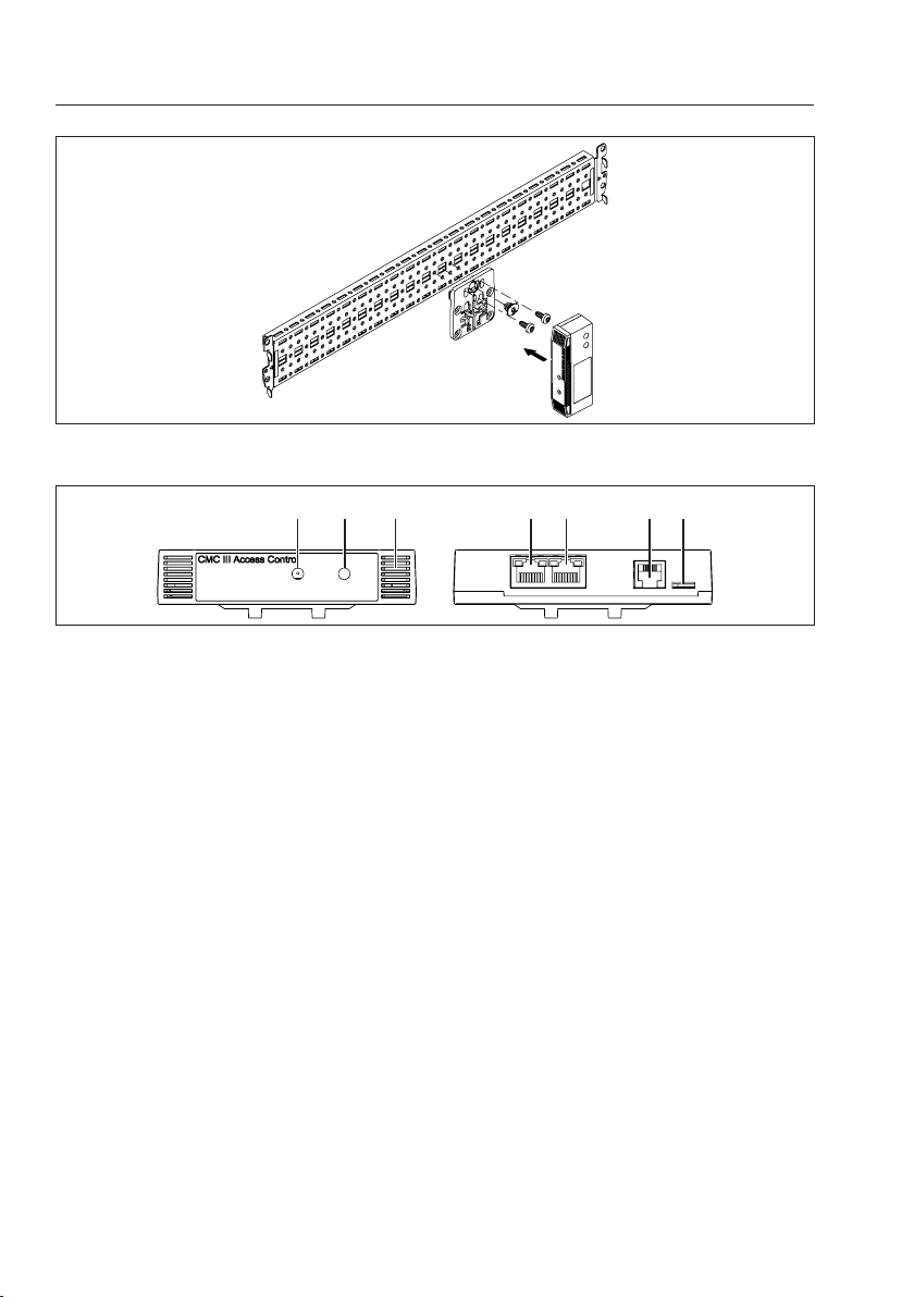
◾ Connect the Access Control with a CAN bus connection cable to the CMC III PU, the PU Compact
or to the neighbouring elements on the CAN bus (fig.5, pos.4, 5).
Display of the status change:
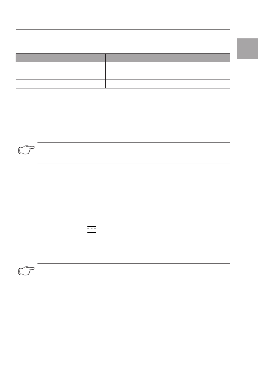
– With the CMC III Access Control, the two green and two red CAN bus LEDs on the CAN bus
connection will flash during the initialisation process. Once initialisation is complete, only the
green LEDs will be illuminated.
– The multi-LED of the Processing Unit flashes continually in the green – orange – red sequence.
– The multi-LED of the Access Control flashes blue continuously.
◾ Press the "C" key on the CMC III PU or the PU Compact (a first audio signal is issued) and keep it
pressed for approx. 3 seconds until a second audio signal is issued.
Display of the status change on the CAN bus LEDs:
– Green LEDs light continuously: CAN bus status "OK".
– Red LEDs light continuously: CAN bus status faulty.
Display of the status change on the multi-LED of the Processing Unit.
– Continuous green light: All units attached to the CAN bus have the "OK" status.
– Continuous orange light: At least one unit attached to the CAN bus has the "warning" status.
– Continuous red light: At least one unit attached to the CAN bus has the "alarm" status.
Display of the status change on the multi-LED of the Access Control:
– Continuous blue flashing: Communication over the CAN bus.
– Green flashing: When the measured value changes or, at the latest, every 5 seconds.
– Continuous red flashing: The Access Control has the "open" status.
– Continuous red light: Invalid measured value.
If the installation is not successful: see section1.1.
Note:
Connection cables in various lengths can be obtained from Rittal.
5.3 Settings
The following parameters can be set or viewed at the CMC III PU or PU Compact web site:
– Value: The current value of the access sensor (0 = door closed, 1 = door open)
– Sensitivity: Distance of sensor from door (1=small, 3=large)
– Delay: Status message delay [s]
– Status: Current status of the access sensor taking account of the delay value
Similarly, the parameters of the connected accessory can be set from the CMC III PU or PU Compact
web site (see section 1.1).
To determine whether any software updates are required: see www.rittal.com or contact
Rittal Service (see section6).
6 Service
For technical questions, please contact:
Tel.: +49(0)2772 505-9052
E-mail: [email protected]
Homepage: www.rittal.com
For complaints or service requests, please contact:
Tel.: +49(0)2772 505-1855
E-Mail: [email protected]
Installation and operation, Service

Unité d'accès CMC III Rittal 11
FR
1 Remarques relatives à la documentation
Cette notice d'installation et d'utilisation succincte s'adresse à du personnel qualifié et chevronné et
contient uniquement les informations essentielles pour le montage, l'installation et le fonctionnement
de l'unité d'accès CMC III (nommé unité d'accès par la suite).
1.1 Autres documents applicables
Notice de montage, d'installation et d'utilisation de l'unité d'accès CMC III.
Elle est disponible sous www.rittal.com et contient les informations complètes relatives à la mise en
œuvre et les caractéristiques techniques de l'unité d'accès dans les domaines suivants:
– Autres possibilités de montage
– Fonctions
– Possibilités de configuration
– Instructions d'utilisation détaillées
– Suppression des défauts
2 Consignes de sécurité
– Le montage et l'installation de l'unité d'accès doivent être réalisés uniquement par du personnel
qualifié et chevronné.
– Le boîtier de l'unité d'accès ne doit pas être ouvert.
– L'unité d'accès ne doit pas se trouver au contact de l'eau, de gaz et de vapeurs agressifs ou
inflammables.
– L'unité d'accès doit être mise en œuvre uniquement dans les conditions ambiantes spécifiées (voir
paragraphe3.4).
Consigne de sécurité selon le règlement REACH (CE) N° 1907/2006
– Le produit contient la substance SVHC « Plomb – N° CAS 7439-92-1 ».
– Selon les indications du fournisseur il n’y a aucun risque pour la santé en cas de contact approprié
avec le produit lors de son utilisation.
– Après son utilisation, le produit doit être mis au rebut de manière appropriée selon les règlements
légaux en vigueur.
3 Description du produit
3.1 Principe de fonctionnement
L'unité d'accès permet de surveiller les portes de baies via un détecteur d'accès infrarouge. Un
lecteur CMC III ainsi qu'une poignée peuvent être raccordés en plus aux interfaces. Le détecteur
d'accès signale l'ouverture ou la fermeture d'une porte. Les codes pour déblocage de porte sont sai-
sis sur le lecteur. Un verrouillage électromagnétique permet ensuite d'ouvrir la porte et de surveiller la
poignée de porte. L'unité d'accès est dotée d'un code d'identification qui lui permet d'être automati-
quement détectée par l'UC CMC III ou l'UC Compact.
3.2 Utilisation conforme au règlement
L'unité d'accès CMC III sert uniquement à contrôler l'accès à une baie serveurs. Elle doit être utilisée
uniquement avec l'UC CMC III ou l'UC Compact. Toute autre utilisation est non conforme.
3.3 Composition de la livraison
– Unité d'accès CMC III
– Accessoires joints à la livraison (voir fig.1)
– Notice d'installation et d'utilisation succincte
Remarques relatives à la documentation, Consignes de sécurité, Description du produit

12 Unité d'accès CMC III Rittal
FR
3.4 Conditions de fonctionnement
L'unité d'accès doit être mise en œuvre uniquement dans les conditions de fonctionnement sui-
vantes:
Condition de fonctionnement Unité d'accès CMC III
Plage de température tolérée 0°C à +55°C
Plage d'humidité tolérée 5% à 95% d'humidité relative, sans condensation
Indice de protection IP 30 selon IEC 60 529
4 Montage
4.1 Instruction de montage
Le montage de l'unité d'accès se réalise conformément à la fig.2.
◾ Placer l'unité d'accès de manière à ce que la face avant, avec émetteur et capteur, soit tournée
vers la porte à surveiller.
◾ Coller le film réflecteur fourni exactement face au capteur infrarouge sur la porte.
Remarque:
la distance entre le capteur infrarouge de l'unité d'accès et le film réflecteur ne doit
pas excéder 10 cm. Repositionner l'unité d'accès en conséquence, si cela s'avère
nécessaire.
5 Installation et utilisation
5.1 Organes de commande et de signalisation
Les organes de commande et de signalisation sont présentés sur la fig.5.
Légende pour la fig.5
1 Récepteur infrarouge
2 Diode infrarouge (émetteur)
3 LED multiple pour l'achage d'état
4 Raccordement CAN-Bus, 24 V
5 Raccordement CAN-Bus, 24 V
6 Raccordement pour la poignée RJ 12
7 Raccordement pour le lecteur CMC III
5.2 Installation
Remarque:
l'Unité Centrale CMC III ou l'UC Compacte doit contenir la version du logiciel
≥V3.15.80. Cela signifie que l'unité d'accès DK7030.202 reçoit automatiquement une
mise à jour logicielle nécessaire via l'UC. C'est le seul moyen de garantir le fonctionne-
ment de l'unité.
◾ Connecter les accessoires de raccordement suivants à la borne correspondante (fig.5, pos.6, 7).
– Serrure à code VX CMC III (DK7030.222, DK7030.223)
– Lecteur de transpondeur VX CMCIII (DK7030.232, DK7030.233)
– Poignée Confort Online VX CMC III (DK7030.610, DK7030.611)
Description du produit, Montage, Installation et utilisation

Unité d'accès CMC III Rittal 13
FR
– Adaptateur Online pour poignée Confort radio VX CMC III (DK7030.624)
– Poignée électromagnétique Ergoform-S (DK7320.700)
– Poignée électromagnétique TS 8 avec fonction de clé maître avec et sans CCP (DK7320.721)
◾ Connecter l'unité d'accès à l'UC CMC III, l'UC Compact ou aux éléments voisins du CAN-Bus via
un câble de raccordement CAN-Bus (fig.5, pos.4, 5).
Achage de la modification d'état:
– Les deux LED CAN-Bus vertes ainsi que les deux rouges de la connexion CAN-Bus sur l'unité
d'accès CMC III clignotent pendant l'initialisation. Puis seules les LED vertes sont encore allu-
mées.
– La LED multiple de l'unité centrale clignote de manière continue dans l'ordre vert – orange –
rouge.
– La LED multiple de l'unité d'accès clignote en bleu de manière continue.
◾ Actionner la touche «C» de l'UC CMC III (un premier signal sonore retentit) et la maintenir action-
née pendant env. 3 secondes jusqu'à ce qu'un deuxième signal sonore retentisse.
Achage de la modification d'état sur la LED du CAN-Bus:
– La LED verte est allumée en continue : état du CAN-Bus «OK».
– La LED rouge est allumée en continue : état défectueux du CAN-Bus.
Achage de la modification d'état sur la LED multiple de l'unité centrale:
– Lumière verte continue : tous les appareils raccordés au CAN-Bus sont dans l'état «OK».
– Lumière orange continue : au moins un appareil raccordé au CAN-Bus est dans l'état «Avertis-
sement».
– Lumière rouge continue : au moins un appareil raccordé au CAN-Bus est dans l'état «Alarme».
Achage de la modification d'état sur la LED multiple de l'unité d'accès:
– Clignotement bleu continu : communication via le CAN-Bus.
– Clignotement vert : lors d'une modification de la valeur de mesure ou au plus tard toutes les
5secondes.
– Clignotement rouge continu: l'unité d'accès est dans l'état «Ouvert».
– Lumière rouge continue: valeur mesurée erronée.
En cas d'échec de l'installation: voir paragraphe1.1.
Remarque:
les câbles de raccordement de diérentes longueurs peuvent être commandés auprès
de la société Rittal.
5.3 Réglages
Les paramètres suivants peuvent être réglés ou consultés sur l'interface WEB de l'UC CMC III ou l'UC
Compact:
– Value: valeur actuelle du détecteur d'accès (0 = porte fermée, 1 = porte ouverte)
– Sensitivity: Espace entre le capteur et la porte (1 = petit, 3 = grand)
– Delay: temporisation du message d'état [s]
– Status: état actuel du détecteur d'accès en tenant compte de la valeur Delay
De même, les paramètres des accessoires raccordés peuvent être réglés sur l'interface WEB de l'UC
CMC III ou l'UC Compact (voir paragraphe 1.1).
Si des mises à jour de logiciel sont éventuellement nécessaires : voir www.rittal.com ou sur demande
au service Rittal (voir le paragraphe6).
Installation et utilisation

14 Unité d'accès CMC III Rittal
FR
6 Service
Pour des questions techniques, veuillez vous adresser à:
Tél.: +49 (0) 2772/505-9052
E-mail: [email protected]
Site Internet: www.rittal.com
Pour des réclamations ou un service, veuillez vous adresser à:
Tél.: +49 (0) 2772/505-1855
E-mail: [email protected]
Service

Rittal CMC III Access Control / Unité d'accès CMC III Rittal 15
Notizen / Notes

◾ Enclosures
◾ Power Distribution
◾ Climate Control
◾ IT Infrastructure
◾ Software & Services
www.rittal.com/contact
You can find the contact details of all
Rittal companies throughout the world here.
RITTAL GmbH & Co. KG
Auf dem Stuetzelberg · 35745 Herborn · Germany
Phone +49 2772 505-0
07.2020/D-0000-00001680-02
Other manuals for Rittal CMC III DK 7030.202
1
Table of contents
Languages:
Other FRIEDHELM LOH IP Access Controllers manuals