FRIEDHELM LOH Rittal CMC III DK 7030.202 User manual

Assembly and operating instructions
CMC III Access Control
DK7030.202

2 Rittal CMC III Access Control
Foreword
EN Foreword
Dear Customer,
Thank you for choosing our CMC III Access Control
(referred to hereafter as "Access Control")!
We wish you every success.
Yours,
Rittal GmbH & Co. KG
Auf dem Stuetzelberg
35745 Herborn
Germany
Tel.: +49(0)2772 505-0
Fax: +49(0)2772 505-2319
E-mail: [email protected]
www.rittal.com
www.rittal.de
We are always happy to answer any technical
questions regarding our entire range of products.

Rittal CMC III Access Control 3
Contents
EN
Contents
1 Notes on documentation......................4
1.1 CE labelling ...................................................... 4
1.2 Storing the documents..................................... 4
1.3 Symbols used in these operating instructions ... 4
1.4 Associated documents..................................... 4
1.5 Area of validity.................................................. 4
2 Safety instructions................................5
2.1 General safety instructions................................ 5
2.2 Service and technical sta................................ 5
3 Product description..............................6
3.1 Functional description and components ........... 6
3.1.1 Function ........................................................... 6
3.1.2 Components .................................................... 6
3.2 Proper use, foreseeable misuse........................ 6
3.3 Scope of supply ............................................... 6
4 Transport and handling.........................7
4.1 Transport.......................................................... 7
4.2 Unpacking........................................................ 7
5 Installation............................................ 8
5.1 Safety instructions............................................ 8
5.2 Siting location requirements.............................. 8
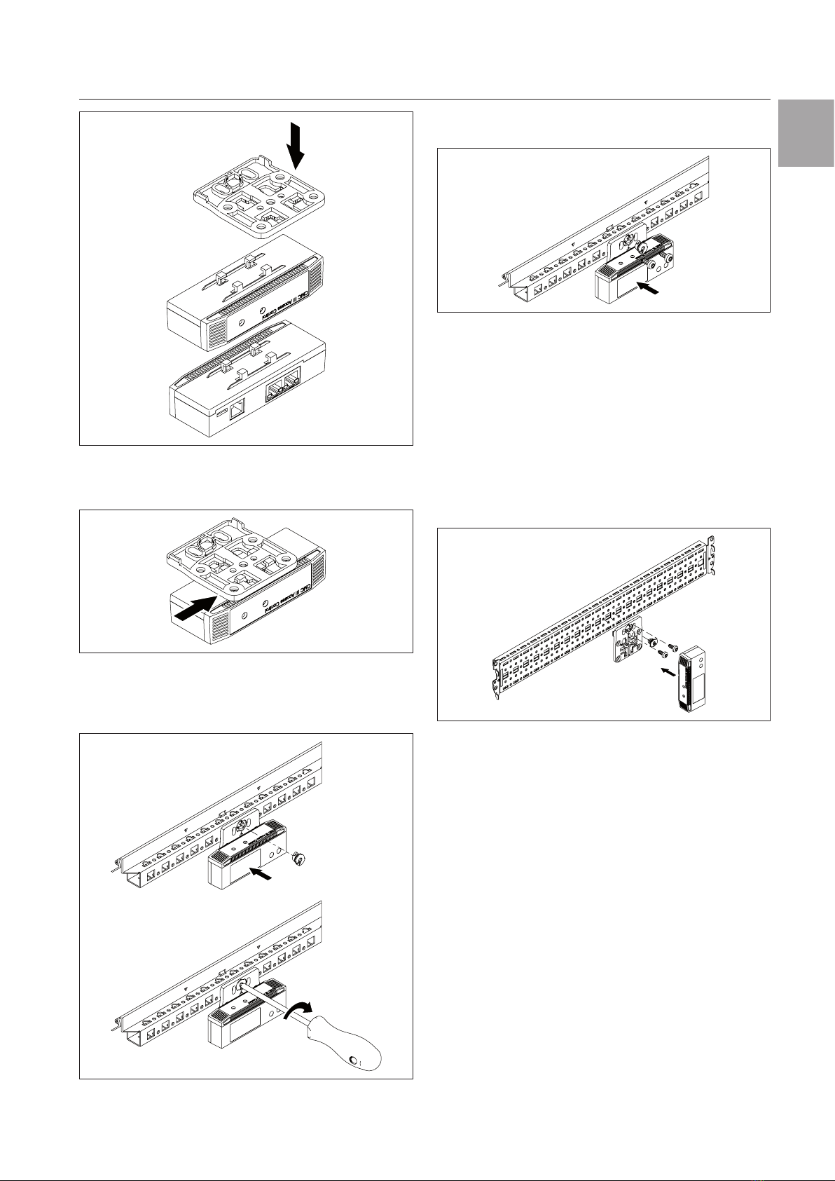
5.3 Installation procedure ....................................... 8
5.3.1 Installation notes............................................... 8
5.3.2 Installation with the provided bracket on the
enclosure frame................................................ 8
5.3.3 Installation with the provided bracket on a
system chassis................................................. 9
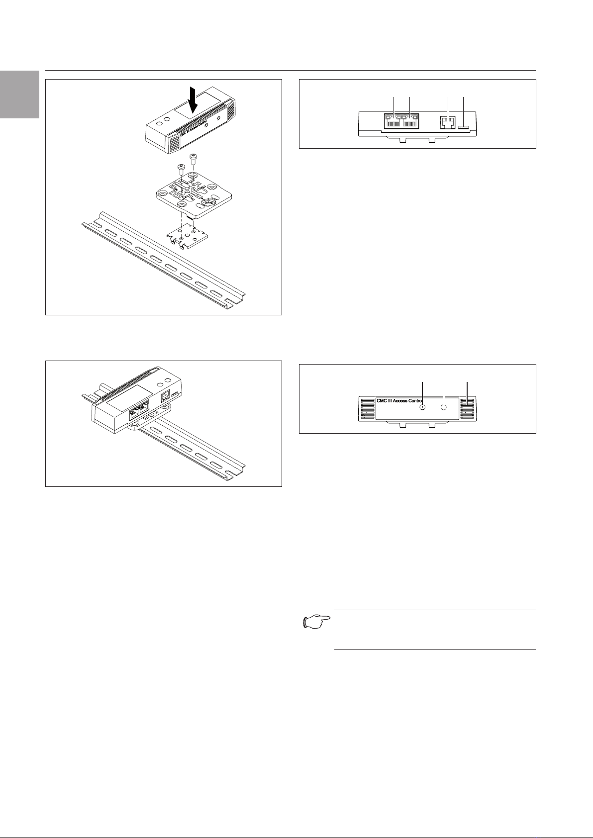
5.3.4 Installation on a top-hat rail............................... 9
5.4 Connection of the Access Control .................. 10
6 Operation...........................................12
6.1 Activating the Access Control......................... 12
6.2 Operating and display elements...................... 12
6.3 LED displays .................................................. 12
6.3.1 Multi-LED displays.......................................... 12
6.3.2 LED displays on the CAN bus connection ...... 12
6.4 Operating the CMCIII Processing Unit from
the website..................................................... 12
6.5 Configuration tab............................................ 12
6.5.1 Specification of the access authorisations ...... 12
6.5.2 Four-eyes principle ......................................... 13
6.5.3 Assignment of reader units to access
modules ......................................................... 14
6.6 Monitoring tab ................................................ 14
6.6.1 Device............................................................ 15
6.6.2 Access ........................................................... 15
6.6.3 Handle ........................................................... 15
6.6.4 KeyPad .......................................................... 16
6.6.5 LED................................................................ 16
6.7 Manual changes to the "access.cmc3" file...... 16
6.7.1 Downloading the file ....................................... 17
6.7.2 Editing the file................................................. 17
6.7.3 Uploading the file............................................ 18
7 Storage and disposal .........................19
7.1 Storage .......................................................... 19
7.2 Disposal ......................................................... 19
8 Technical specifications......................20
9 Customer service addresses..............21

4 Rittal CMC III Access Control
1 Notes on documentation
EN 1 Notes on documentation
1.1 CE labelling
Rittal GmbH & Co. KG hereby confirms that the CMCIII
CAN Access Control is compliant with the EC EMC
Directive 2014/30/EC. An appropriate declaration of
conformity has been prepared. It can be provided on
request.
1.2 Storing the documents
The assembly and operating instructions as well as
all applicable documents are an integral part of the
product. They must be passed to those persons who
are engaged with the unit and must always be avail-
able and on hand for the operating and maintenance
personnel.
1.3 Symbols used in these operating in-
structions
The following symbols are used in this documentation:
Danger!
Hazardous situation leading directly to
death or serious injury if the instruc-
tions are not followed.
Warning!
Hazardous situation which may lead
directly to death or serious injury if the
instructions are not followed.
Caution!
Hazardous situation which may lead to
(minor) injuries if the instructions are
not followed.
Note:
Identification of situations that can lead to
material damage.
◾ This symbol indicates an "action point" and shows
that you should perform an operation or procedure.
1.4 Associated documents
– Installation and Short User Guide
– Assembly and operating instructions for compatible
base systems, e.g. CMC III Processing Unit
Note:
Additional compatible base systems can be
found on the internet at www.rittal.com for
model no. DK 7030.202. The term "base
systems" is used in these instructions as
placeholder for the various systems.
– Installation and Short User Guide for the connected
accessories (e.g. DK 7030.233 transponder reader).
1.5 Area of validity
These instructions apply to software version V3.17.00.
This documentation shows the English screenshots.
English terminology is also used in the descriptions of
the individual parameters on the CMC III Processing
Unit (base systems) website. Depending on the set
language, the displays on the CMC III Processing Unit
(base systems) website may be dierent (see Assembly
and operating instructions for the CMCIII Processing
Unit (base systems)).

Rittal CMC III Access Control 5
2 Safety instructions
EN
2 Safety instructions
2.1 General safety instructions
Please observe the subsequent general safety instruc-
tions for the installation and operation of the system:
– Use only original Rittal products or products rec-
ommended by Rittal in conjunction with the Access
Control.
– Please do not make any changes to the Access
Control that are not described in this manual or in the
associated manuals.
– The operating reliability of the Access Control is only
warranted in case of use as intended and according
to the rules. The technical specifications and limit
values stated must not be exceeded under any cir-
cumstances. In particular, this applies to the specified
ambient temperature range and IP degree of protec-
tion.
– The Access Control must not be opened. The unit
does not contain any parts that need servicing.
– Operating the system in direct contact with water,
aggressive materials or inflammable gases and va-
pours is prohibited.
– Other than these general safety instructions, ensure
you also observe the specific safety instructions
when the tasks described in the following chapters
are performed
REACH safety information in accordance with
Regulation (EC) No 1907/2006
– The product contains the SVHC "Lead – CAS
no.7439-92-1".
– The manufacturer specifies that no health risks of any
kind arise during use of the product when handled
properly.
– After use, the product must be disposed of properly
in accordance with the applicable statutory regula-
tions.
2.2 Service and technical sta
– The mounting, installation, commissioning, mainte-
nance and repair of this unit may only be performed
by qualified mechanical and electro-technical trained
personnel.
– Only properly instructed personnel may work on a
unit while in operation.

6 Rittal CMC III Access Control
3 Product description
EN 3 Product description
3.1 Functional description and components
3.1.1 Function
The Access Control serves to monitor rack doors via
an infrared access sensor. In addition to this, a CMC
III reader unit and a handle can be connected to the
interfaces. The access sensor reports to the CMC III
Processing Unit (base systems) whether the door is
open or closed. Codes for the door release are input
on the coded lock. The door can then be opened and
monitored with an electromagnetic handle. The Access
Control has an identification that allows it to be detect-
ed automatically by the CMC III Processing Unit (base
systems).
Note:
In the following text, the designation
"CMCIII Processing Unit" refers to the
"CMC III Processing Unit" variants and also
to the base systems. All text passages that
apply only to a specific variant are identified
accordingly.
3.1.2 Components
The device consists of a compact plastic housing in
RAL7035 with a ventilated front in RAL 9005.
3.2 Proper use, foreseeable misuse
The CMCIIIAccess Control serves exclusively to mon-
itor access to a server enclosure. It may only be used
together with the CMCIIIProcessing Unit. Any other
use is not permitted.
The unit is state of the art and built according to rec-
ognised safety regulations. Nevertheless, incorrect use
may result in damage to or faults with the system and
other material assets.
Consequently, the unit must only be used properly
and in a technically sound condition! Any malfunctions
which impair safety should be rectified immediately!
Follow the operating instructions!
The intended use also includes the observance of the
documentation provided and fulfilling the inspection
and maintenance conditions.
Rittal GmbH & Co. KG is not liable for any damage
which may result from failure to comply with the docu-
mentation provided. The same applies to the non-ob-
servance of the valid documentation for any deployed
accessories and the base systems.
Inappropriate use may result in danger. Inappropriate
use includes:
– Use of impermissible tools.
– Improper operation.
– Improper rectification of malfunctions.
– Use of accessories not approved by Rittal GmbH &
Co. KG.
3.3 Scope of supply
– CMCIII Access Control
– Accessories provided (Fig.1)
– Installation Guide and Short User Guide
2x2x
5x
1x1x 1x
M4x10 5,5x13
Fig.1: Accessories provided

Rittal CMC III Access Control 7
4 Transport and handling
EN
4 Transport and handling
4.1 Transport
The unit is delivered in a carton.
4.2 Unpacking
◾ Remove the unit's packaging materials.
Note:
After unpacking, the packaging materials
must be disposed of in an environmentally
friendly way. They consist of the following
materials:
Polyethylene film (PE film), cardboard.
◾ Check the unit for any damage that may have oc-
curred during transport.
Note:
Damage and other faults, e.g. incomplete
delivery, should be reported immediately,
in writing, to the shipping company and to
Rittal GmbH & Co. KG.
◾ Remove the unit from the PE film.
◾ Remove the protective film from the front cover of the
device.

8 Rittal CMC III Access Control
5 Installation
EN 5 Installation
5.1 Safety instructions
◾ Please observe the valid regulations for installation
in the country in which the Access Control is in-
stalled and operated, and the national regulations for
accident prevention. Please also observe any internal
company regulations, such as work, operating and
safety regulations.
◾ The technical specifications and limit values stated
must not be exceeded under any circumstances. In
particular, this applies to the specified ambient tem-
perature range and IP degree of protection.
◾ If a higher IP protection class is required for a special
application, the Access Control must be installed in
an appropriate housing or in an appropriate enclo-
sure with the required IP degree of protection. Under
certain circumstances, the integral infrared sensor
may then no longer function.
5.2 Siting location requirements
To ensure the unit functions correctly, the conditions
for the installation site of the unit specified in section 8
"Technical specifications" must be observed.
Electromagnetic interference
– Interfering electrical installations (high frequency)
should be avoided.
5.3 Installation procedure
There are generally several options for installing the
Access Control:
1. Installation on the frame of the enclosure or IT
enclosure using the bracket included.
2. Installation with the provided bracket on a system
chassis.
3. Installation on a top-hat rail using the bracket in-
cluded along with a spring clip.
5.3.1 Installation notes
◾ Install the Access Control in such a way that the front
with the transmitter and receiver points toward the
door to be monitored.
◾ Preferably, install the Access Control in such a way
that the infrared access sensor points toward the
lock-side and not the hinge-side of the door to be
monitored.
◾ Because the angle of the reflecting foil changes fast-
er, an opened door will be detected faster.
◾ The Access Control must be positioned so that it is
ventilated with an adequate amount of air and the
ventilation slots are not covered.
◾ Glue the reflecting foil provided at the door position
exactly opposite the infrared access sensor.
◾ Ensure observance of the minimum and maximum
clearances between the sensor and the reflecting foil
that depend on the set value for "sensitivity" specified
in the following table.
Sensitivity Min. clearance
[mm]
Max. clearance
[mm]
1 25 40
2 25 70
3 25 100
Tab. 1: Minimum and maximum clearances
Note:
In the delivered state, the sensitivity is preset
to the value "2".
5.3.2 Installation with the provided bracket on
the enclosure frame
The provided bracket is used for installation on the
frame of an IT enclosure.
◾ For installation on a TS IT enclosure, break o the
protruding lugs at the rear of the bracket.
Fig.2: Preparing the bracket for installation on a TS IT enclo-
sure
◾ Place the Access Control on the bracket from above.

Rittal CMC III Access Control 9
5 Installation
EN
Fig.3: Attaching the sensor to the bracket
◾ Move the sensor sideways slightly on the bracket so
that it latches into place.
Fig.4: Latching the sensor into place on the bracket
◾ Fasten the bracket, including Access Control, at the
desired position in the enclosure or the IT enclosure
by making a quarter-turn of the connector.
Fig.5: Mounting the sensor in the enclosure or IT enclosure
◾ Optionally secure the bracket using the two screws
included in the scope of delivery.
Fig.6: Optional securing of the bracket
5.3.3 Installation with the provided bracket on a
system chassis
The provided bracket is used for installation on a sys-
tem chassis.
◾ Place the Access Control on the bracket from above
and latch it similar to the installation on the enclosure
frame.
◾ Fasten the bracket, including Access Control, at the
desired position in the enclosure on the system chas-
sis by making a quarter-turn of the connector.
Fig.7: Fastening the sensor to a system chassis
◾ Also always secure the bracket with the two provid-
ed bolts.
5.3.4 Installation on a top-hat rail
The sensor can also be mounted on a top-hat rail using
the bracket along with the spring clip included in the
scope of delivery.
◾ First screw the bracket onto the spring clip provided
for installation on a top-hat rail.
◾ Then place the Access Control on the bracket and
latch it into place.

10 Rittal CMC III Access Control
5 Installation
EN
Fig.8: Fastening the bracket to the spring clip
◾ Latch the spring clip into place at the desired position
on the top-hat rail.
Fig.9: Sensor with spring clip on the top-hat rail
5.4 Connection of the Access Control
The Access Control is supplied with the necessary op-
erating voltage via the CAN bus connection. A separate
power supply unit does not need to be connected.
◾ If necessary, connect the following connection ac-
cessories to the appropriate connection.
– CMCIII coded lock VX (DK7030.222,
DK7030.223)
– CMCIII transponder reader VX (DK7030.232,
DK7030.233)
– CMC III online comfort handle VX (DK7030.610,
DK7030.611)
– CMC III Online adaptor for the radio comfort handle
VX (DK7030.624)
– Electromagnetic Ergoform-S handle (DK 7320.700)
– Electromagnetic TS 8 handle with master key func-
tion with and without CCP (DK 7320.721)
◾ Use a CAN bus connection cable to connect the
Access Control to a CAN bus interface on the
CMCIIIProcessing Unit or the neighbouring compo-
nent on the CAN bus (Fig.10, item4).
45 67
Fig.10: Rear of the Access Control
Legend
4 CAN bus connection, 24 V
5 CAN bus connection, 24 V
6 Connection for RJ12 handle
7 Connection for CMC III reader unit
The following CAN bus connection cables from the
CMCIII accessories range can be used:
– DK 7030.090 (length 0.5m)
– DK 7030.091 (length 1m)
– DK 7030.092 (length 1.5m)
– DK 7030.093 (length 2m)
– DK 7030.480 (length 3m)
– DK 7030.490 (length 4m)
– DK 7030.094 (length 5m)
– DK 7030.095 (length 10m)
312
Fig.11: Front of the Access Control
Legend
1 Infrared receiver
2 Infrared diode (transmitter)
3 Multi-LED for status display
The sensor software is updated, if necessary, after
being connected. The status LED of the Access Con-
trol glows blue throughout the entire update process
and also flashes purple while the sensor itself is being
updated.
In addition, the status LED of the CMC III Processing
Unit flashes white and a corresponding message ap-
pears on the website.
Note:
No settings can be modified as long as the
update process is running.
The update of the sensor is complete when the follow-
ing conditions have been fulfilled:
1. The LEDs on the bus connection of the sensor light
green.
2. The multi-LED of the sensor behind the front panel
flashes blue and also green, yellow or red depend-
ing on the status of the sensor.
Further components are connected as a daisy chain.

Rittal CMC III Access Control 11
5 Installation
EN
◾ If necessary, connect another component (e.g.
another sensor type) to the second, free CAN bus
interface of the Access Control (Fig.10, item 5).
Status change display:
– The two green and the two red CAN bus LEDs on
the CAN bus connection flash.
– The multi-LED of the Processing Unit flashes con-
tinually in the sequence green – yellow – red.
– The multi-LED of the Access Control flashes blue
continuously
◾ Press the "C" key on the CMCIIIProcessing Unit (an
initial audio signal will sound) and keep it pressed
for approx. 3 seconds until a second audio signal is
heard.
Note:
See section6.3.1 "Multi-LED displays" for a
list of all of the multi-LED displays.
Note:
If a new sensor is registered on the bus or
the CMC III Processing Unit is restarted,
the Ergoform-S electro-magnetic handle is
released temporarily.
Status change display on the CAN bus LEDs
– Continuous green LEDs: CAN bus status "OK".
– Continuous red LEDs: CAN bus status defective.
Status change display on the multi-LED of the
Processing Unit
– Continuous green light: All devices connected to the
CAN bus have the status "OK".
– Continuous orange light: At least one device con-
nected to the CAN bus has the status "Warning".
– Continuous red light: At least one device connected
to the CAN bus has the status "Alarm".
Status change display on the multi-LED of the
Access Control
– Continuous blue flashing: Communication via the
CANbus.
– Green flashing: When the measured value changes,
or at least every 5 seconds.
– Continuous red flashing: The Access Control has the
"open" status.
– Continuous red light: Invalid measured value.

12 Rittal CMC III Access Control
6 Operation
EN 6 Operation
6.1 Activating the Access Control
After connecting the Access Control to a neighbouring
component using a CAN bus connecting cable, the
Access Control starts automatically (see section5.4
"Connection of the Access Control"). Separate activa-
tion is not required.
6.2 Operating and display elements
312
Fig.12: Front of the Access Control
Legend
1 Infrared receiver
2 Infrared diode (transmitter)
3 Multi-LED for status display
45 67
Fig.13: Rear of the Access Control
Legend
4 CAN bus connection, 24 V
5 CAN bus connection, 24 V
6 Connection for RJ12 handle
7 Connection for CMC III reader unit
6.3 LED displays
A multi-LED for the status display is integrated into the
front of the Access Control (Fig.12, item 3). Further
LEDs are located at the rear on the CAN bus connec-
tion (Fig.13, item4 and item5).
6.3.1 Multi-LED displays
The status of the Access Control can be read on the
multi-LED.
Colour Status
Green When the measured value changes or, at
the latest, every 5 seconds.
Purple A Access Control software update is
being carried out
Blue Communication via the CAN bus.
Red The Access Control has the "alarm"
status.
Tab. 2: Multi-LED flashing codes
6.3.2 LED displays on the CAN bus connection
A red and a green LED are located on the CAN bus
connection. They display the status of the CAN bus.
Colour Status
Green (con-
tinuously lit)
Communication via the CAN bus possible.
Red (flash-
ing)
Transmission fault.
Tab. 3: LEDs for the CAN bus connection
6.4 Operating the CMCIII Processing Unit
from the website
After logging on to the CMC III Processing Unit, the
web interface for operating the device is displayed.
◾ First select the "CMCIII-GRF2" entry in the navigation
area.
6.5 Configuration tab
Note:
If the access authorisations are managed
via RiZone as of version3.6, changes must
be implemented in RiZone. In this case, no
changes may be made on the CMCIII.
Similar to the CMC III Processing Unit, the Configu-
ration tab can be used to individually configure the
access rights for the Access Control (Device Rights
button) and the alarm messages (Alarm Configura-
tion button).
6.5.1 Specification of the access authorisations
The access authorisations for the door to be monitored
are also defined in the Configuration tab (Access
Configuration button).
◾ First select the "Processing Unit" node in the naviga-
tion area.
◾ Select the Configuration tab in the configuration
area.
To add a new transponder card:
◾ Hold the transponder card in front of the transponder
reader before selecting the "Access Configurations"
dialogue.
Regardless of the next work steps:
◾ In the Security group frame, click on the Access
Configuration button.
The "Access Configurations" dialogue opens.
To add a new access code:
◾ Below the list of access codes / transponder cards
that have already been added in the Access group
frame of the "Access Configuration" dialogue, click
the Add button.

Rittal CMC III Access Control 13
6 Operation
EN
A new line is added to the end of the table.
To configure an access authorisation (transpond-
er card or access code):
◾ Select in the Access group frame the line with the
required entry to adapt the associated settings.
◾ Click the Edit button.
The "Access Configuration" dialogue opens.
Parameter Explanation
Type Configuration of an access via transpond-
er card ("Card" entry) or access code
("Keycode" entry).
Code Number of the transponder card or ac-
cess code for access.
User Selection of the user authorised for the
access. The user must have been created
in advance.
Information Specific additional information for the ac-
cess. This text is also added for the user
in the CMCIIIProcessing Unit logfile.
Tab. 4: Parameters group frame
All connected Access Control and virtual access con-
trollers are displayed in the Devices group frame.
Parameter Explanation
Use Enable or disable individual access mod-
ules.
Device
Name
Specific description of the Access Control
or (virtual) access controller to which the
access module to be switched is con-
nected.
Serial Num-
ber
Serial number of the Access Control or
(virtual) access controller to which the ac-
cess module to be switched is connected.
Tab. 5: Devices group frame
Note:
A user must be assigned to the access
code or transponder card. Otherwise,
access isn't possible even if the correct ac-
cess code is entered or with the appropriate
transponder card.
To delete an access authorisation (transponder
card or access code):
◾ Select the line with the required entry you wish to
delete.
◾ If necessary, select another entry by keeping the shift
key pressed. All lines from the first entry selected to
the last entry selected (inclusive) are selected.
◾ If necessary, select further entries by keeping the
"Ctrl" key pressed. These lines are added individually
to the selection.
◾ Click the Delete button.
All selected access authorisations are immediately
deleted without a confirmation prompt.
Note:
If a transponder card is held in front of the
transponder reader again after the access
authorisation has been deleted, a corre-
sponding line is added at the end of the ta-
ble as in the case where a new transponder
card is added.
6.5.2 Four-eyes principle
When the four-eyes principle is activated, two persons
must identify themselves to open a handle or a door. To
do this, two dierent persons must register themselves
with their transponder cards or their number code with-
in a set time interval on the same card reader.
To activate the four-eyes principle:
◾ Assign the "AccessAck" user to a transponder card
or a number code in the "Access Configurations"
dialogue.
By default, this user is present on each CMCIII Pro-
cessing Unit and belongs to the "Access" group to
which no further rights are assigned.
◾ If the "AccessAck" user and/or the "Access" group
are not present (e.g. because prior to an update of
the CMCIII Processing Unit, all storage spaces are
already occupied), you must manually create the user
and the group (refer to the CMC III Processing Unit
assembly and operating instructions).
◾ Set the time interval in the "Confirm Timeout" field
within which the two users must register for activated
four-eyes principle.
After saving this assignment, the four-eyes principle
governs the complete access control. Consequently,
at least two transponder cards or two access codes
are required for each reader unit.
Note:
After activation of the four-eyes principle,
each reader unit should also be assigned
a transponder card or a number code with
the "AccessAck" user. This user is always
required so that a closed handle or door
can be opened.
To open a handle or a door:
◾ The first user registers himself/herself with his/her
transponder code or number code on the reader unit.
◾ The second user registers himself/herself with his/her
transponder code or number code within the set time
interval on the same reader unit.
At least one of the two users must be the "AccessAck"
user. The order with which the users register does not
matter.

14 Rittal CMC III Access Control
6 Operation
EN Note:
The time interval within which the two users
must register can also be specified directly
in the "access.cmc3" file (see section 6.7
"Manual changes to the “access.cmc3”
file").
6.5.3 Assignment of reader units to access
modules
By default, on input of an authorised code or holding
an authorised card at a reader unit, all handles and
virtual access controllers assigned to the associated
access authorisation in the Access group frame are
opened or switched, respectively (see section 6.5.1
"Specification of the access authorisations").
Reader units and access modules can now be as-
signed to each other in the Keypad Mapping group
frame. This allows you to control which handles and
doors can be opened depending on the associated
reader unit.
– No assignment stored: All access modules as-
signed to the associated access authorisation in the
Access group frame are authorised.
– Assignment between the reader unit and the
access module(s) stored: Only those access
modules assigned to the associated reader unit are
authorised. These access modules must also be
assigned in the Access group frame as a device to
the associated access authorisation.
To configure the assignment of a reader unit to
specific handles and doors:
◾ Mark in the Keypad Mapping group frame the line
with the access module to which the reader unit is
connected, and to which you want to assign specific
handles and doors.
◾ Click the Edit button.
The "Access Configuration" dialogue opens.
Parameter Explanation
Use Enable or disable individual access
modules for the previously selected reader
unit.
Device
Name
Specific description of the Access Control
or (virtual) access controller to which the
access module to be switched is con-
nected.
Serial Num-
ber
Specific description of the Access Control
or (virtual) access controller to which the
access module to be switched is con-
nected.
Tab. 6: "Access Configuration" dialogue
Note:
If no access module is activated in the
"Use" column, the reader unit will be as-
signed to all access modules. In this case,
all handles and doors activated for the
transponder card or the number code will
be opened, irrespective of which reader unit
is used.
6.6 Monitoring tab
All settings for the Access Control, such as the sen-
sitivity of the integrated access sensor, are made on
the Monitoring tab. You have a choice between two
display options:
– Tree display: This allows fast, targeted access to
individual parameters.
– Graphical display: This provides a quick overview of
the most important Access Control parameters.
When the lower-level "Device", "General", etc. en-
tries are displayed (Fig.14, item 1) after selecting the
"CMCIII-GRF2" level, switch to the graphical display as
follows:
◾ Click the coloured "graphic" symbol behind the
"CMCIII-GRF2" entry that resembles a stylised dia-
gram (Fig.14, item 2).
1
2
Fig.14: Tree display
The display switches to the graphical display (Fig.15).
The status of the door and of the handle lever is dis-
played here. The sensibility of the IR access sensor or
the times can also be set and the door can be released
(Fig.15, item2).
When the graphical display is shown after selecting
the "CMCIII-GRF2" level, switch to the tree display as
follows:
◾ Click the grey-scale "graphic" symbol shown behind
the "CMCIII-GRF2" entry (Fig.15, item1).

Rittal CMC III Access Control 15
6 Operation
EN
1
Fig.15: Graphical display
The display changes to the tree display (Fig.14) and
you can now access the specific setting values.
In the following sections 6.6.1 "Device" to 6.6.4 "Key-
Pad", only those parameters which you can modify are
described. There are also display values that provide
information.
6.6.1 Device
General settings for the Access Control are configured
at the "Device" level.
Parameter Explanation
Description Specific description of the Access Con-
trol.
Location Installation location of the Access Control.
Tab. 7: Settings at "Device" level
In addition, parameters that provide detailed informa-
tion about the Access Control , such as its software
and hardware versions, are also displayed. You should
have such information available, in particular to enable
rapid troubleshooting when requesting assistance from
Rittal.
6.6.2 Access
Settings for the integral access sensor are performed
at the "Access" level.
Parameter Explanation
DescName Specific description of the access sensor.
Command Can be used in tasks to monitor the
"open/closed" door status using an exter-
nal sensor instead of the integral infrared
sensor. The "Sensitivity" parameter must
be set to "0" for this.
Parameter Explanation
Sensitivity Distance between the sensor and the
door (1 = small, 3 = large). Entering the
value "0" deactivates the integral access
sensor ("Closed" status) and the status is
controlled using the "Command" param-
eter.
Delay Time delay after which the status display
changes.
Tab. 8: Settings at "Access" level
Note:
The "Command" parameter is automati-
cally set to the standard value "Open" if a
new sensor is registered on the bus or the
CMCIII Processing Unit is restarted.
The following parameters are also displayed for the
access sensor:
Parameter Explanation
Value The current value of the access sensor (0
= door closed, 1 = door open).
Status The current status of the access sensor
taking account of the delay value.
Tab. 9: Displays at "Access" level
6.6.3 Handle
Settings for the handle used are performed at the
"Handle" level.
Parameter Explanation
DescName Specific description of the handle used.
Command By selecting the "Unlock" entry, an elec-
tromagnetic handle can be unlocked via
the CMC III Processing Unit website (sta-
tus "Unlocked") so that it can be opened.
Accordingly, a handle can be locked
(status "Locked") by selecting the "Lock"
entry so that it cannot be opened.
By selecting the "Delay" entry, the handle
is unlocked for the period of time specified
in the "Delay" field and is subsequently
locked again.
Delay The time-controlled actuation of the
electromagnet can be set using this
parameter.
Tab. 10: Settings at "Handle" level
The following parameters are also displayed for the
handle used:

16 Rittal CMC III Access Control
6 Operation
EN Parameter Explanation
Value Current status of the handle used (0 =
handle closed, 1 = handle open).
Status Current locking status.
Tab. 11: Displays at "Handle" level
Note:
The logic above for the "Value" parameter
applies to handles DK 7030.610 and DK
7030.611. The logic may be inverted for
other handle systems (0 = handle open, 1 =
handle closed).
Note:
There is no error message if the handle is
disconnected from the Access Control. The
handle status changes to "Inactive" and a
corresponding message is generated in the
log information. The status change can be
queried in a task and linked with an action.
Note:
If the handle is opened with a master key,
the CMCIIIPU displays an alarm message.
This can be eliminated again by closing the
handle.
6.6.4 KeyPad
The settings for the coded lock and transponder reader
are configured at the "KeyPad" level.
Parameter Explanation
DescName Specific description of the coded lock or
transponder reader used.
Command Selecting the "On" entry activates the
connected coded lock or the transponder
reader.
Accordingly, a connected reader unit can
be deactivated by selecting the "O" entry
so that it cannot be used to open the
door.
Tab. 12: Settings at "KeyPad" level
The following parameters are also displayed for the
coded lock/transponder reader:
Parameter Explanation
Status Indicates whether a coded lock or
transponder reader has been connected
(active) or not (inactive), or the reader unit
has been deactivated (o).
Tab. 13: Displays at "KeyPad" level
6.6.5 LED
The settings for the LED display in the handle are con-
figured at the "LED" level.
Parameter Explanation
Mode Control of the LED display in the handle.
"O": LED display switched o perma-
nently.
"Access": Display in accordance with
the switching status of the handle or the
status of the Access Control.
"Access & beeper": Similar to "Access",
an acoustic signal also sounds in the
event of a fault.
"CMC": Display in accordance with the
status of the CMC III PU.
"CMC & beeper": Similar to "CMC", an
acoustic signal also sounds in the event
of a fault.
"Task": Display in accordance with the
evaluation of a task ("LED.Command"
variable).
"Task & beeper": Similar to "Task", an
acoustic signal also sounds in the event
of a fault.
Command The colour of the LED can be set when
the "Task" mode is selected. The colour
is retained until the task is next initiated. If
"Custom" is selected, the colour can be
defined using the three components: red,
green and blue.
Red Red component of the colour.
Green Green component of the colour.
Blue Blue component of the colour.
Tab. 14: Settings at the "LED" level
6.7 Manual changes to the "access.cmc3"
file
Alternatively, the access authorisation settings can also
be made directly in the "access.cmc3" file. This file is
created automatically in the "upload" directory of the
CMCIII Processing Unit when it is started for the first
time.

Rittal CMC III Access Control 17
6 Operation
EN
Note:
If the "access.cmc3" file is removed from
the folder, access is only then possible
using the three predefined access codes
"1001", "1002" and "1003". All other access
authorisations have to initially be added
again to a newly created file.
6.7.1 Downloading the file
Note:
The following descriptions assume that you
establish an (S)FTP connection using the
"FileZilla" program. If another program is
used, the file may have to be downloaded
and uploaded in a dierent way.
◾ First establish an FTP or SFTP connection to the
CMCIII Processing Unit from a PC (see the assembly
and operating instructions for the CMCIII Processing
Unit).
◾ In the left-hand subwindow (PC), switch to the folder
where you wish to locally save the "access.cmc3"
file.
◾ Switch to the "upload" folder in the right-hand sub-
window (CMCIII PU).
◾ Right-click the "access.cmc3" file and select the
"Download" action.
◾ Disconnect the (S)FTP connection between the PC
and CMCIII PU.
If there is no "access.cmc3" file in the "upload" directo-
ry, this has to be created first.
◾ When using a coded lock: Input any sequence of
numbers on the coded lock and confirm using the
"Enter" key. The file is now generated in the "upload"
folder.
◾ When using a transponder reader: Hold any tran-
sponder card in front of the reader unit. The file is
now generated in the "upload" folder.
◾ Establish an (S)FTP connection between the PC and
CMCIII PU again and download the file.
◾ Disconnect the (S)FTP connection between the PC
and CMCIII PU again.
6.7.2 Editing the file
The file can now be edited using a text editor. Rittal
recommends using "Notepad++" for this instead of the
standard "Notepad" editor installed under Windows.
This is available online as freeware.
Fig.16: "access.cmc3" file in Notepad++
The file is structured as follows:
– Lines starting with a "#" are comment lines. These
contain basic information on the CMCIII Processing
Unit.
– Lines with "Key" or "Crd" as first entry contain the
authorised access codes if a numeric coded lock is
used, or the authorised card numbers of the tran-
sponder cards if a transponder reader is used (see
section 6.5.1 "Specification of the access authorisa-
tions").
– The line with "4-Eyes" as first entry contains the time
interval for the registration in the four-eyes principle
(see section 6.5.2 "Four-eyes principle").
– Lines with "Keypad" as first entry contain the assign-
ment of reader units to individual access modules
(see section 6.5.3 "Assignment of reader units to
access modules").
Access codes and transponder cards
The lines for the access codes and the transponder
cards contain the following entries:
Parameter Explanation
Key Access code containing up to eight digits
for a coded lock for authorised access.
Crd Card number of a transponder card for
authorised access.
User User to be entered in the CMCIII Pro-
cessing Unit logfile when the coded lock
is opened with the associated access
code or on opening with the associated
transponder card. This user has to exist in
the CMCIII PU.
Information Specific additional information for the ac-
cess. This text is also added for the user
in the CMCIIIProcessing Unit logfile.
Handle Serial number of the Access Control or
(virtual) access controller to which the
access module to be switched is connect-
ed. Several comma-separated entries for
dierent Access Control units can also be
added here.
Tab. 15: Entries for access codes and transponder cards

18 Rittal CMC III Access Control
6 Operation
EN Note:
Each line contains the parameter "Key" or
"Crd" depending on whether the line applies
to a coded lock or transponder reader.
The entries are explained in detail using the following
example configuration.
Fig.17: Example configuration
– Handle 1 is opened using access code "1234" (line
11 in the editor window). User "cmc" and the infor-
mation "Info 1" are entered in the CMCIII PU logfile.
– Handle 2 is opened using access code "123456"
(line 12). User "Rittal" and the information "Info 2" are
entered in the CMCIII PU logfile.
– Both handles are opened using access code
"12345678" (line 13). User "admin" and the informa-
tion "Info 3" are entered in the CMCIII PU logfile.
In lines 15 to 17, a transponder card has also been as-
signed to each of the users. These transponder cards
open the same handles as the access codes above.
The respective users and associated information are
entered in the CMCIII PU logfile.
Time interval for the four-eyes principle
The time interval for registration in the four-eyes princi-
ple is specified in the line with the "4-Eyes" entry.
Parameter Explanation
4-Eyes Time interval in seconds within which the
two persons must register with their tran-
sponder cards or their number code.
Tab. 16: Time interval for the four-eyes principle
Assignment of reader units to access modules
The lines for the assignment of reader units to access
codes contain the following entries:
Parameter Explanation
Keypad Serial number of the Access Control or
the (virtual) access controller to which the
reader unit is connected with the following
assigned handles or doors.
Parameter Explanation
Handle Serial number of the Access Control or
(virtual) access controller to which the
access module to be switched is connect-
ed. Several comma-separated entries for
dierent Access Control units can also be
added here.
Tab. 17: Assignment of reader units to access modules
Note:
If no access module is assigned to the
"Handle" entry, the reader unit will be as-
signed to all access modules. In this case,
all doors activated for the transponder card
or the number code will be opened, irre-
spective of which reader unit is used.
6.7.3 Uploading the file
Once all entries have been made in the "access.cmc3"
file, this file has to be stored in the "upload" directory
on the CMCIII Processing Unit again.
◾ Establish an FTP or SFTP connection to the CMCIII
Processing Unit from a PC again.
◾ Switch to the "upload" folder in the right-hand sub-
window (CMCIII PU).
◾ In the left-hand subwindow (PC), switch to the folder
where you have stored the revised version of the
"access.cmc3" file.
◾ Right-click the "access.cmc3" file and select the
"Upload" action.
◾ If the file cannot be uploaded this way, first delete the
existing "access.cmc3" file from the "upload" directo-
ry and then upload the file from the PC again.
◾ Finally, disconnect the (S)FTP connection between
the PC and CMCIII PU.
The access authorisations have now been updated.

Rittal CMC III Access Control 19
7 Storage and disposal
EN
7 Storage and disposal
7.1 Storage
If the device is not used for a long period, Rittal recom-
mends that it be disconnected from the mains power
supply and protected from damp and dust.
7.2 Disposal
Since the Access Control consists mainly of the
"housing" and "circuit board" parts, the device must be
passed on to the electronic waste recycling system for
disposal.

20 Rittal CMC III Access Control
8 Technical specifications
EN 8 Technical specifications
Technical specifications CMCIII Access Control
Model no. DK7030.202
W x H x D (mm) 110 x 30 x 40
Operating temperature range 0°C…+55°C
Storage temperature -45°C…+85°C
Operating humidity range 5%…95% relative humidity, non-condensing
Protection category IP 30 to IEC 60 529
Inputs and outputs CAN bus (RJ 45) 2 x
Handle (RJ12) 1 x
Connection for CMC III reader unit 1 x
Operation/signals LED display OK/Warning/Alarm/CAN bus status
Tab. 18: Technical specifications
Other manuals for Rittal CMC III DK 7030.202
1
Table of contents
Other FRIEDHELM LOH IP Access Controllers manuals
Popular IP Access Controllers manuals by other brands

CDVI
CDVI Digicode Mifare PCV123D installation manual

Vanderbilt
Vanderbilt ACTpro EM1030 installation guide

Motorline professional
Motorline professional MLS4 User's and installer's manual

Viking
Viking ES-3 Technical practice

Idemia
Idemia MorphoWave Compact Quick user guide

Viking
Viking K-1900-8 Technical practice