92016602
W ARNING
15/20A LCDI Device 30A LCDI Device
TEST BEFORE EACH USE
1. PRESS RESET BUTT ON
2. PLUG LCDI INT O POWER
RECEPT ACLE
3. PRESS TEST BUTT ON,
RESET BUTT ON SHOULD
POP UP
4. PRESS TEST BUTT ON,
FOR USE
DO NOT USE IF ABOVE TEST
F AILS
WHEN GREEN LIGHT IS ON
IT IS WORKING PROPERL Y
RESET TEST
W ARNING
TEST BEFORE EACH USE
1. PRESS RESET BUTT ON
2. PLUG LCDI INT O POWER
RECEPT ACLE
3. PRESS TEST BUTT ON,
RESET BUTT ON SHOULD
POP UP
4. PRESS TEST BUTT ON,
FOR USE
DO NOT USE IF ABOVE TEST
F AILS
WHEN GREEN LIGHT IS ON
IT IS WORKING PROPERL Y
RESET
TEST
FRP014
Electrical Rating Tables
250V Receptacles and Fuse Types
AMPS 15 20* 30
RECEPTACLE
TIME-DELAY TYPE FUSE
(or HACR circuit breaker) 15 20 30
HACR–Heating,AirConditioning,Refrigeration
* Maybeusedfor15Ampapplicationsiffusedfor15Amp
NOTE:265voltunitsarenormallyhardwired.Forproperinstallation
followtheNationalElectricalCode(NEC)orlocalcodesand
ordinances.
FUSE/CIRCUIT
BREAKER
Use ONLY type and size fuse or HACR cir-
cuit breaker indicated on unit’s rating plate.
Proper current protection to the unit is the
responsibility of the owner. NOTE: A time
delay fuse is provided with 265V units.
GROUNDING
Unit MUST be grounded from branch circuit
through service cord to unit, or through
separate ground wire provided on per-
manently connected units. Be sure that
branch circuit or general purpose outlet is
grounded. The eld supplied outlet must
match plug on service cord and be within
reach of service cord. Refer to Table 1 for
proper receptacle and fuse type. Do NOT
alter the service cord or plug. Do NOT use
an extension cord.
RECEPTACLE
The eld supplied outlet must match plug on
service cord and be within reach of service
cord. Refer to Table 1 for proper receptacle
and fuse type. Do NOT alter the service
cord or plug. Do NOT use an extension
cord.
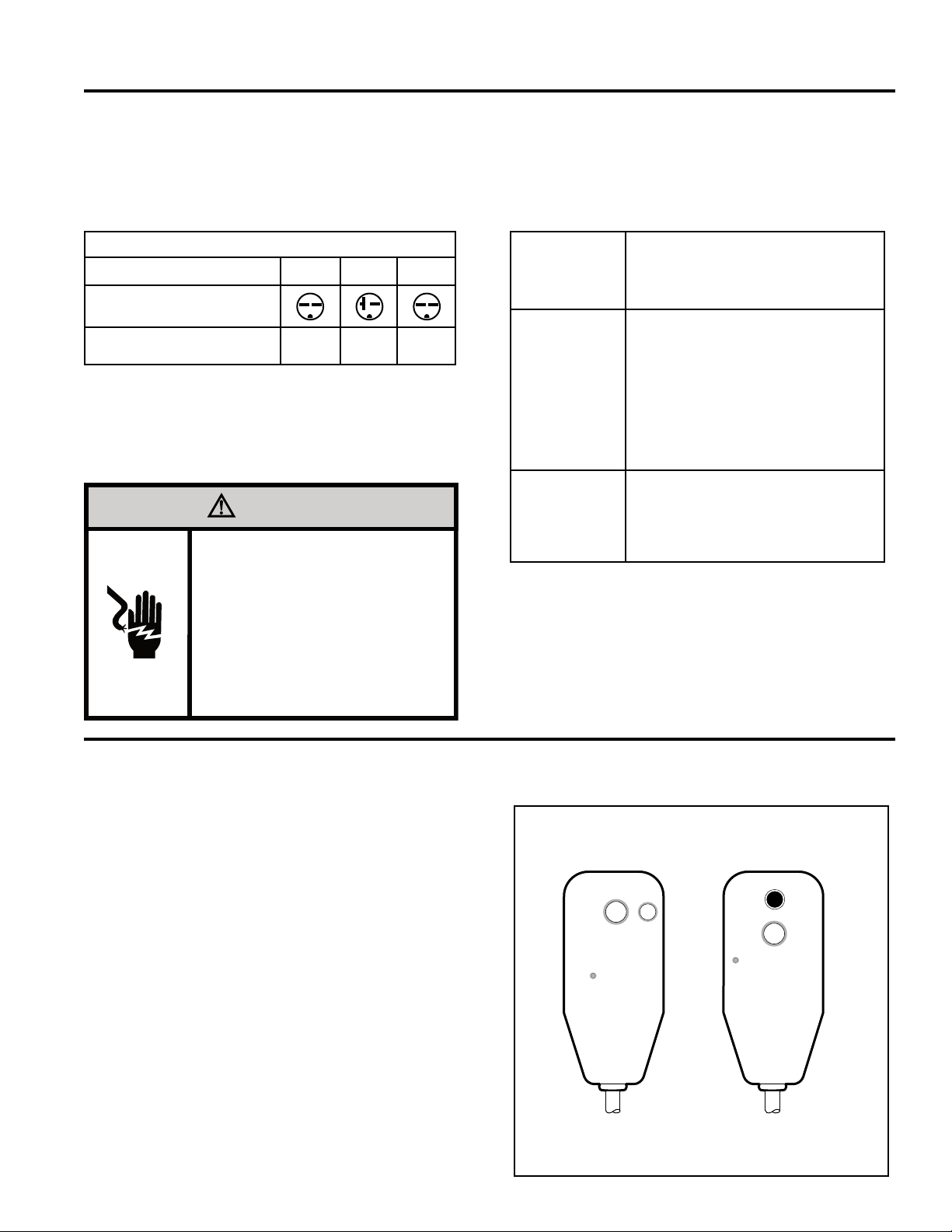
All Friedrich230/208VPTAC units areshipped from thefactorywitha
LeakageCurrentDetectionInterrupter(LCDI)equippedpowercord.The
LCDIdevicemeetstheULandNECrequirementsforcordconnectedair
conditionerseffectiveAugust2004.
Totestyourpowersupplycord:
1. Plugpowersupplycordintoagrounded3prongoutlet.
2. PressRESET.
3. PressTEST(listenforclick;Resetbuttontripsandpopsout).
4. PressandreleaseRESET(listenforclick;Resetbuttonlatches
andremainsin).Thepowersupplycordisreadyforoperation.
NOTE: TheLCDIdeviceisnotintendedtobeusedasaswitch.
Oncepluggedintheunitwilloperatenormallywithouttheneedtoreset
theLCDIdevice.
IftheLCDIdevicefailstotripwhentestedorifthepowersupplycordis
damageditmustbereplacedwithanewsupplycordobtainedfromthe
productmanufacturer,andmustnotberepaired.
Power Cord Information (230/208V models only)
Figure 2
Typical LCDI Devices
NOTE: UseCopperConductorsONLY.WiresizesareperNEC,checklocalcodesforoverseasapplications.
Table 1
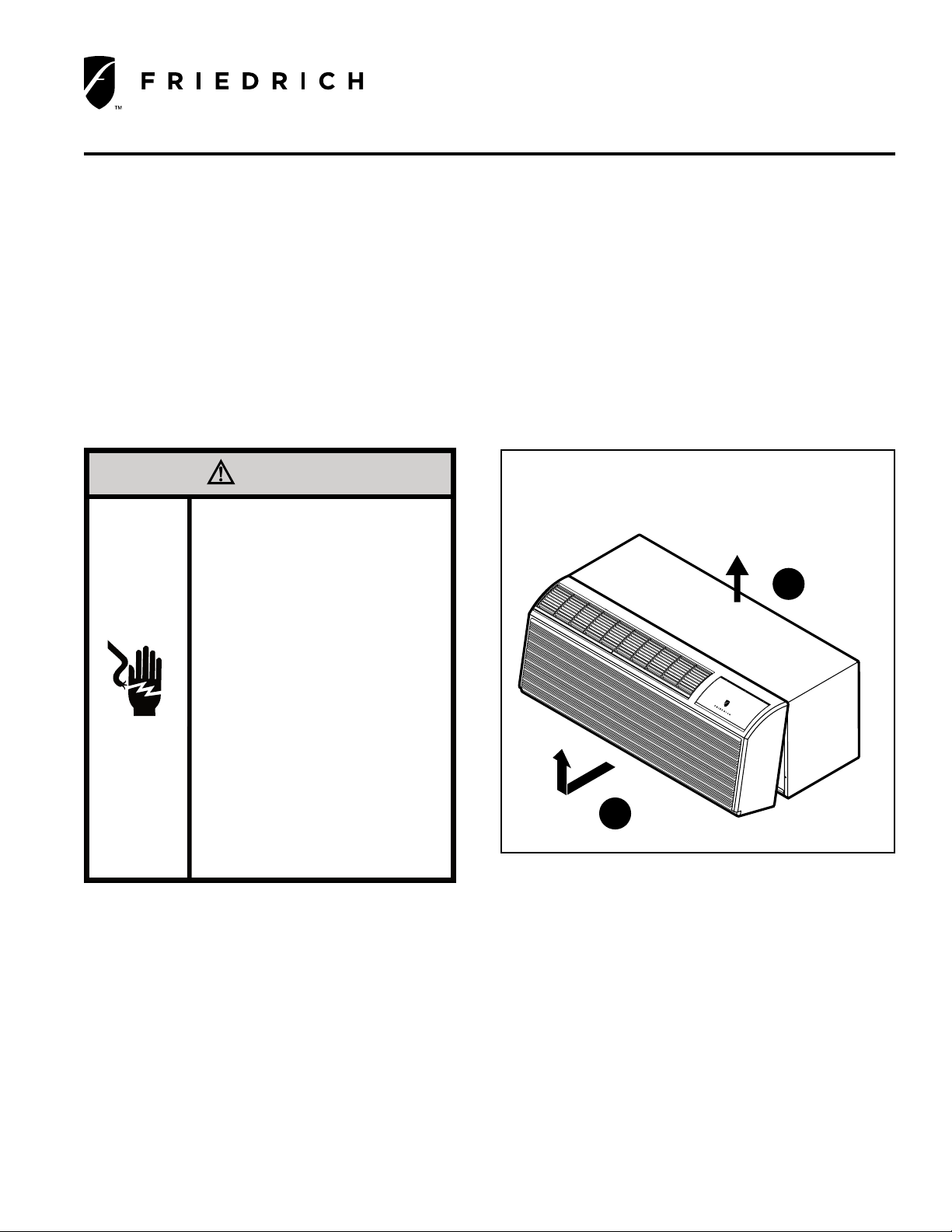
WARNING
Electrical Shock Hazard
Turn off electrical power before service
or installation.
ALL electrical connections and wiring
MUST be installed by a qualified
electrician and conform to the National
Code and all local codes which have
jurisdiction.
Failure to do so can result in property
damage, personal injury and/or death.
Installation Instructions POWER CORD ACCESSORY KIT