manuals.online logo
Brands
  1. Home
  2. •
  3. Brands
  4. •
  5. Friedrich
  6. •
  7. Dehumidifier
  8. •
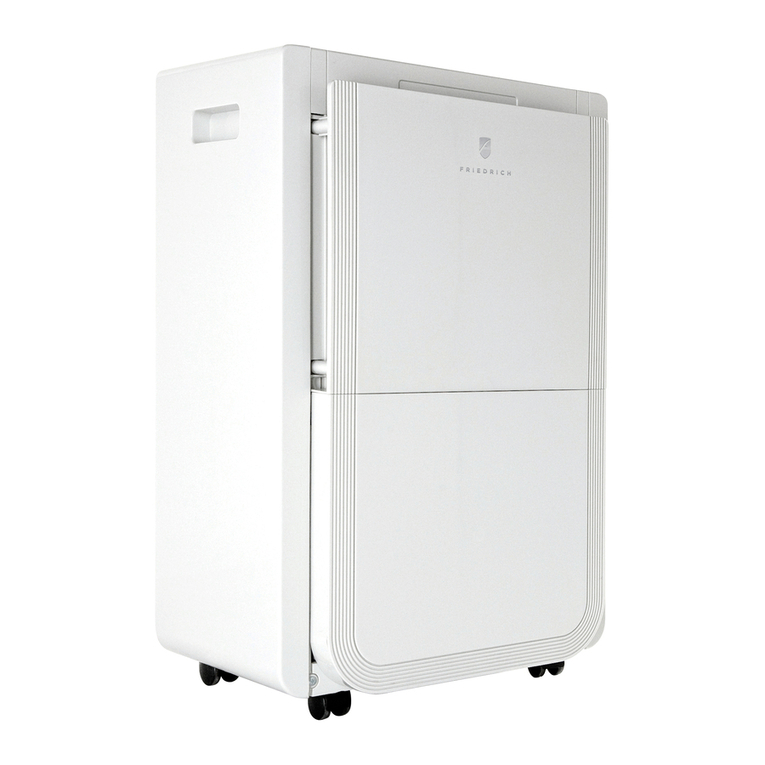
  9. Friedrich D70D Guide

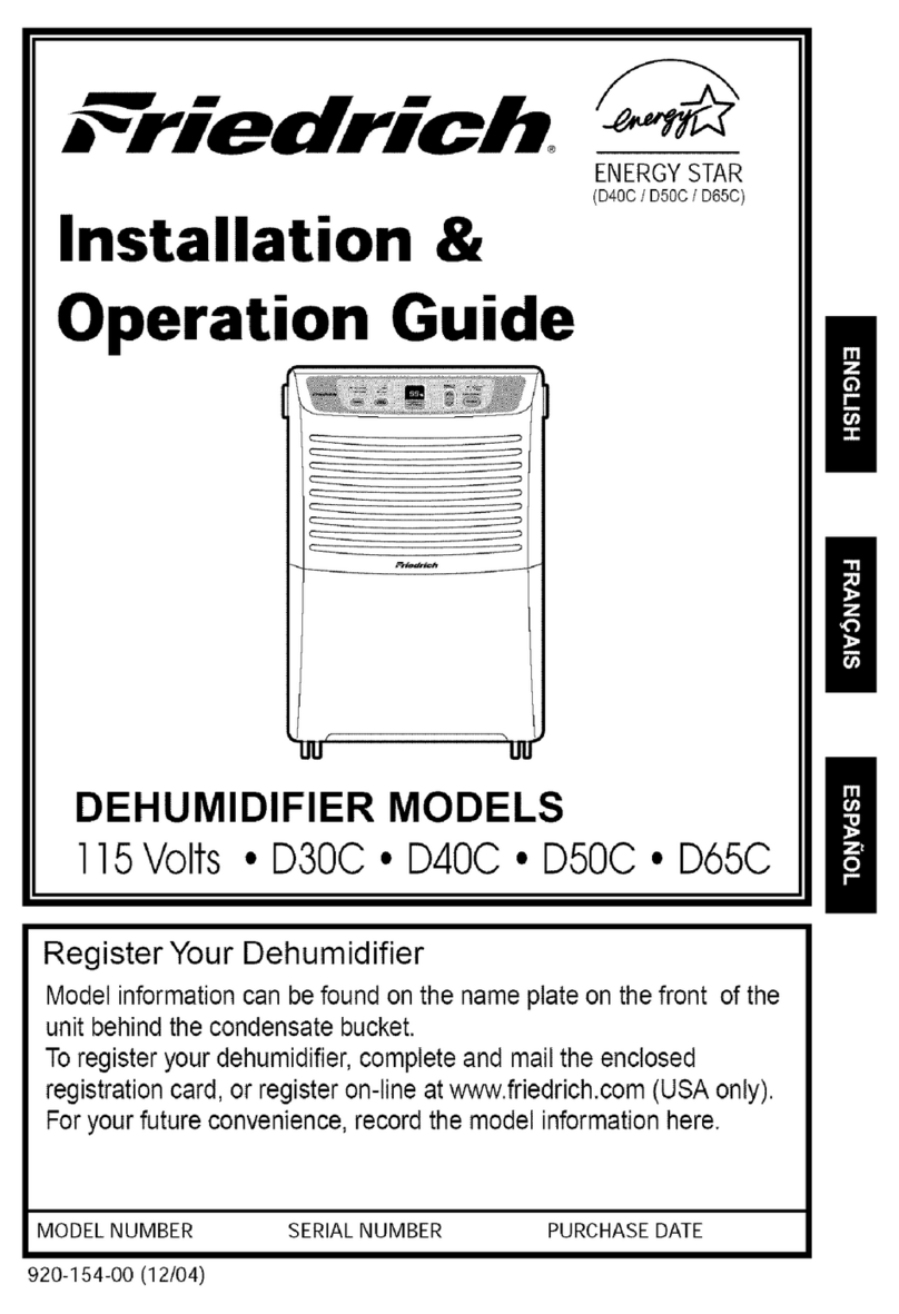
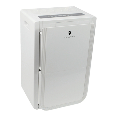
Friedrich D70D Guide

This manual suits for next models

2

Other Friedrich Dehumidifier manuals

Friedrich D25ANP User manual

Friedrich

Friedrich D25ANP User manual

Friedrich D30C Troubleshooting guide

Friedrich

Friedrich D30C Troubleshooting guide
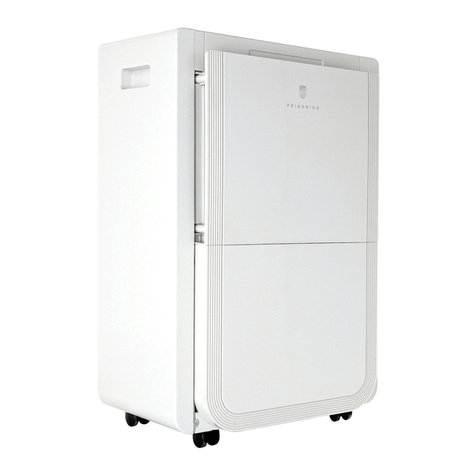
Friedrich D25D User manual

Friedrich

Friedrich D25D User manual

Friedrich D30 Original operating instructions

Friedrich

Friedrich D30 Original operating instructions

Friedrich D25D User manual

Friedrich

Friedrich D25D User manual

Friedrich D30B User manual

Friedrich

Friedrich D30B User manual

Friedrich D25ANP User manual

Friedrich

Friedrich D25ANP User manual

Friedrich D30C Building instructions

Friedrich

Friedrich D30C Building instructions

Friedrich DH30 User manual

Friedrich

Friedrich DH30 User manual

Friedrich D25ANP User manual

Friedrich

Friedrich D25ANP User manual
Friedrich D25BNP User manual

Friedrich

Friedrich D25BNP User manual

Friedrich D25ANP User manual

Friedrich

Friedrich D25ANP User manual
Friedrich D25ANP User manual

Friedrich

Friedrich D25ANP User manual

Friedrich D70BP User manual

Friedrich

Friedrich D70BP User manual

Friedrich D30A Original operating instructions

Friedrich

Friedrich D30A Original operating instructions

Friedrich D25ANP User manual

Friedrich

Friedrich D25ANP User manual

Friedrich D25ANP User manual

Friedrich

Friedrich D25ANP User manual

Friedrich D30A Building instructions

Friedrich

Friedrich D30A Building instructions
Popular Dehumidifier manuals by other brands

GET DHMD102 User instructions

GET

GET DHMD102 User instructions

Daewoo COL1471 user manual

Daewoo

Daewoo COL1471 user manual

WILMS KT 1130 manual

WILMS

WILMS KT 1130 manual

Aprilaire E080 quick start guide

Aprilaire

Aprilaire E080 quick start guide

fisair DFLEX Series user manual

fisair

fisair DFLEX Series user manual

Daitsu CD031IU-DFA owner's manual

Daitsu

Daitsu CD031IU-DFA owner's manual

Fehom PDGT701BE user manual

Fehom

Fehom PDGT701BE user manual

Trotec TTR 400 D User instructions

Trotec

Trotec TTR 400 D User instructions

Westpoint MDF1-30AE instruction manual

Westpoint

Westpoint MDF1-30AE instruction manual

SOLIS easy dry compact user manual

SOLIS

SOLIS easy dry compact user manual

Sinclair R-9112 instruction manual

Sinclair

Sinclair R-9112 instruction manual

Kenmore 580.54701 owner's manual

Kenmore

Kenmore 580.54701 owner's manual

Demargo DM828NF Installation and operating instructions
Demargo

Demargo DM828NF Installation and operating instructions

Altrad Lescha LDH 600 Original instructions

Altrad Lescha

Altrad Lescha LDH 600 Original instructions

BOMANN LE 1150 CB instruction manual

BOMANN

BOMANN LE 1150 CB instruction manual

SPT SD-46 instruction manual

SPT

SPT SD-46 instruction manual

Haier HD458 user manual

Haier

Haier HD458 user manual

Logik L20DHW12 instruction manual

Logik

Logik L20DHW12 instruction manual

manuals.online logo
manuals.online logoBrands
  • About & Mission
  • Contact us
  • Privacy Policy
  • Terms and Conditions

Copyright 2025 Manuals.Online. All Rights Reserved.

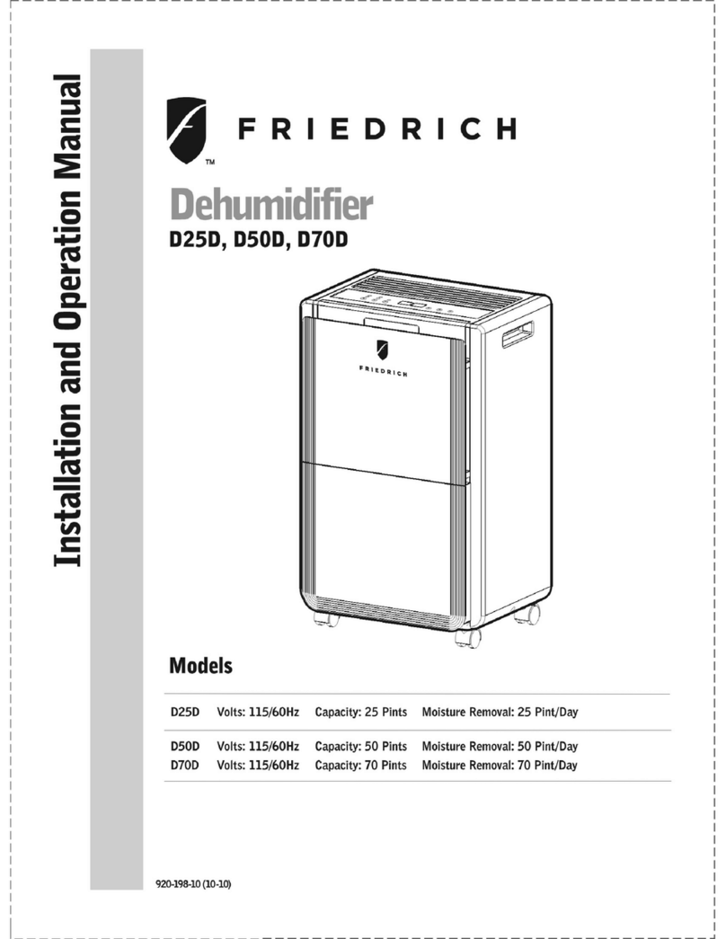
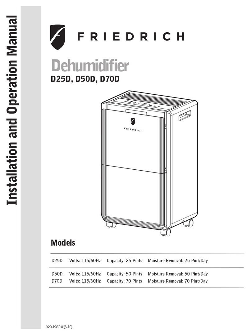
Models D25D, D50D, D70D
Dehumidifier
Service & Parts Manual
Dehumidifier-2010 Svc Parts (4-2010)
Important points on service, and Flow chart
for inspecting and repairing the unit
Troubleshooting
Appearance and Control panel
Technical specifications
Refrigerator system diagram
Schematic wiring diagram
Exploded view and Parts Lists
Warranty
............... 1
............................................. 2
........................ 3
.............................. 4-6
.......................... 7
.............................. 8
................... 9-12
....................................................... 13
Get other manuals https://www.bkmanuals.com
IMPORTANT POINTS ON SERVICE OPERATING SAFETY
Please follow these instructions carefully :
FLOW CHART FOR INSPECTING AND REPAIRING THE UNIT
- 1 -
Unplug the unit to avoid any danger from electric shock before disassembling the unit for
repair.
If there is any sound of the refrigerant circulating when in operation, avoid touching the
cooling coils.
If you need to perform any welding or soldering, be sure you are in a well ventilated area.
Only a qualified professional should perform any welding on the unit.
When repairing the unit, the specifications listed in this manual must be strictly adhered
to when replacing any components.
When replacing any electrical components they should be factory approved units.
Be sure that any electrical components are properly wired and in place.
Electricity shutdown Dehumidifier
doesn't work
Check if drain bucket
water level switch
is broken
Check fuses on
main switch Can not dehumidify Humidity sensor
is broken
Humidity setting on
continuous operation
Over load protector is
faulty
Check if air filter is
clogged
Capacitors are faulty Compressor doesn't
work
Refrigerant is leaking
Maintain
&
repair system
Supply Nitrogen 15Kg/cm² from low
pressure side and locate the leakage
Use oxygen acetylene and 5% silver
iron to fill cracks and holes
Pump vacuum for at
least 15 minutes
After filling with
refrigerant proceed to test run
Get other manuals https://www.bkmanuals.com
Solution
TROUBLESHOOTING
Problem
- 2 -
Possible causes
Dehumidifier
doesn't work
Fan doesn't work
Evaporator is
frosted
Can not
dehumidify or the
dehumidifcation
volume is too low
Loud noise and
vibration
Dehumidification
water overflows
Compressor
doesn't work
Motor is broken
Bad plug or wire is broken
Low voltage
Filter is too dirty
Uneven floor
Low temp and humidity
Refrigerant is leaking
Filter is dirty
Compressor is broken
Still under the 3 min
protection
Electricity shutdown or low
voltage
Sound of flowing water
Micro switch is broken
Drain bucket is broken
Environment temp is too low
Motor or compressor is loose
Repair or replace
Repair or replace
Call the local electricity
company
Clean filter
Move to level place or use
blocks
Normal
Detect the leakage and fill with
refrigerant
Clean filter
Repair or replace
Wait until if goes back to
function after 3 min
Wait for electricity to be
restored
Normal, it is the sound when
the refrigerant is flowing
Repair or replace
Repair or replace
Stop use temporarily
Tighten screws
Get other manuals https://www.bkmanuals.com
APPEARANCE
- 3 -
OUTLET FOR
DEHUMIDIFIED
DRY AIR
CONTINUOUS
DRAINAGE HOLE
Electricity cable
ROLL CASTORS
DRAIN BUCKET
MOIST AIR
INTAKE
HANDLE
CONTROL PANEL AIR FILTER
BUCKET FULL LAMP
Water tank is full,and
lamp lights.
FAN SPEED
High / Low
POWER
On / Off
CONTROL PANEL
DEFROST LAMP
When low temperature,
unit gets into defrosting
mode and lamp lights.
TIMERS
When unit operates, press
"TIMER" set hours unit will off
after set hours.
When unit stand-by, press
"TIMER" set hours unit will on
after set hours.
Setting timer from 1~24 hours.
To cancel the timer, proceed
as above but set the "timer off"
to zero hours.
When machine is running, it displays the current temperature. Press
the "Timer" button to set the machine to shut off automatically after a
specified amount of time. 10 seconds after displaying the timer, the
display will change back to current temperature.
CURRENT TEMP / TIMER SET DISPLAY
When machine is running, it displays the current
humidity. Press "▲" or "▼" to select humidity
setting. The humidity is adjusted in an increment
of 5% by each pressing of "▲" or "▼". Adjustable
range is within 30%RH to 90%RH. 10seconds
after setting humidity, the display will change
back to the current humidity.
SET HUMIDITY / CURRENT HUMIDITY DISPLAY Press the ℃/℉
switch buttons,
it will switch at
sequence of
℃ and ℉.
Get other manuals https://www.bkmanuals.com
TECHNICAL SPECIFICATIONS
DEHUMIDIFYING CAPACITY Pint/day
WIRE SPECIFICATION 10A 125V 18AWG*3C
- 4 -
25 (at 80°F , 60%RH)
ITEM UNIT
OUTER DIMENSION
RATED VOLTAGE
RUNNING CURRENT
COMPRESSOR
OPERATING
CYCLE
PROTECTOR
MODEL
INPUT
POWER
CAPILLARY
CONDENSER
REFRIGERANT
WEIGHT
13.46(W) * 21.46(H) * 9.84(D)
115 / 60
300
35/300
0.086(O.D.)*0.047(I.D.)*19.685(L)
2R10S21FPI
D25D
32
MODEL
INPUT
POWER
FAN MOTOR
LS-16T2-04
47
5/250
OPERATING
CYCLE
EVAPORATOR 1R10S21FPI
Inches
V/Hz
A
W
uF/V
Inches
R410A/oz
Lbs
W
uF/V
4.6
35D042-A2-ABDA
MRA12228-12095
5.28
WATER TANK CAPACITY Pint 11
Get other manuals https://www.bkmanuals.com
TECHNICAL SPECIFICATIONS
- 5 -
DEHUMIDIFYING CAPACITY Pint/day
WIRE SPECIFICATION 10A 125V 18AWG*3C
50 (at 80°F , 60%RH)
ITEM UNIT
OUTER DIMENSION
RATED VOLTAGE
RUNNING CURRENT
COMPRESSOR
OPERATING
CYCLE
PROTECTOR
MODEL
CAPILLARY
CONDENSER
REFRIGERANT
WEIGHT
115 / 60
40/300
0.086(O.D.)*0.047(I.D.)*39.37(L)
2R12S21FPI
D50D
44
MODEL
INPUT
POWER
FAN MOTOR
LS-16T2-02-N2
47
6/250
OPERATING
CYCLE
EVAPORATOR 2R12S21FPI
V/Hz
A
uF/V
R410A/oz
W
uF/V
5.9
35D052-A2-ABLL
MRA12274-12095
9.32
WATER TANK CAPACITY 16
14.96(W) * 23.43(H) * 12.01(D)
Inches
Lbs
Pint
Inches
Get other manuals https://www.bkmanuals.com
TECHNICAL SPECIFICATIONS
- 6 -
DEHUMIDIFYING CAPACITY Pint/day
WIRE SPECIFICATION 10A 125V 18AWG*3C
70 (at 80°F , 60%RH)
ITEM UNIT
OUTER DIMENSION
RATED VOLTAGE
RUNNING CURRENT
COMPRESSOR
OPERATING
CYCLE
PROTECTOR
MODEL
CAPILLARY
CONDENSER
REFRIGERANT
WEIGHT
115 / 60
40/300
0.086(O.D.)*0.047(I.D.)*31.50(L)
2R12S21FPI
D70D
44
MODEL
INPUT
POWER
FAN MOTOR
LS-16T2-06
47
6/250
OPERATING
CYCLE
EVAPORATOR 2R12S21FPI
V/Hz
A
uF/V
A
R410A/oz
W
uF/V
7.7
41T068-A2-AMLI
MRA12272-12082
12.03
WATER TANK CAPACITY 16
14.96(W) * 23.43(H) * 12.01(D)
Inches
Lbs
Pint
Inches
Get other manuals https://www.bkmanuals.com
EVAPORATOR
CONDENSER
CAPILLARY TUBE DRYER
COMPRESSOR ASS'Y
FAN MOTOR
PTC(HEATER)
- 7 -
REFRIGERATOR SYSTEM DIAGRAM
Get other manuals https://www.bkmanuals.com
SCHEMATIC WIRING DIAGRAM
NO
COM.
CN 3
FAN-L
F/MOTOR
L
E
WHITE
BLUE
T.sensor
CN 4
MICRO
SWITCH
TRANSFORMER
CN 1
CN 2
BLUE
FUSE
YELLOW
CONTROL BOARD
CN 1
N
N1
N2
BLUE
WHITE
CAPACITOR
RED
115V~60Hz
COMPRESSOR
N
RED
OLP
WHITE
BLUE
CAPACITOR
T3.15AL 125V
H.sensor
CN 7
BLACK
BROWN
BLUE
CN 8
CN 2
CN 6
FAN-H
P6 P7
D6951-900
- 8 -
SCHEMATIC WIRING DIAGRAM
NO
COM.
CN 3
P6 P7
COMPRESSOR
F/MOTOR
N
L
E
WHITE
BLUE
RED
T.sensor
CN 4
MICRO
SWITCH
TRANSFORMER
CN 1
CN 2
BLUE
U
FSE
YELLOW
CONTROL BOARD
CN 1
N
N
N
BLACK
WHITE
CAPACITOR
RED
115V~60Hz
OLP
WHITE
BLUE
CAPACITOR
T3.15AL 250V
CN 7
H.sensor
BLACK
CN 8
CN 2
CN 5
FAN-L FAN-H
D6951-870
D25D
SCHEMATIC WIRING DIAGRAM
D50D, D70D
Get other manuals https://www.bkmanuals.com
EXPLODED VIEW
2
1
3
4
5
6
7
37
9
8
11
12
22
23
25
26
31 10
17
16
42
47
44
43
48
15
18
19
20
21
39
40
38
35
27
33
41
36
32
14
46
45
51
13
24
28
29
30
34
50
49
- 9 -
D25D
Get other manuals https://www.bkmanuals.com