Frigicoll Kaysun KWF 140 ACS User manual

Water Heat Exchanger Wire Controller
KWF 140 ACS
OWNER’S MANUAL
Thank you for purchasing our product. Please read this manual carefully before
running the unit and keep it for future reference.

CONTENTS
Safety precautions.............................................. 1
Technical data andcharacteristic......................... 2
Overview...............................................................3
Operation instruction............................................. 6
Error handling..................................................... 16
● This manual gives detailed description of the
precautions that should be brought to your attention during
operation.
● In order to ensure correct service of the wired
controller please read this manual carefully before using
the unit.
● For convenience of future reference, keep this manual
after reading it.

Safety
precautions
W
A
RNING
Please assign the distributor or professionals to install the device.
Improper installation may lead to electric shock or fire.
Do not install the unit in a place vulnerable to leakage of flammable gases.
Once flammable gases are leakedand left around the wire controller, fire may occur.
Do not operate with wet hands or let water enter the wire controller. Otherwise,
the device lifespan will be shortened.

2. Technical data and
characteristic
2.1 Technical
data
1) Input voltage : 10VAC.
2) Operating environment temperature of wired controller: -10°C~+43°C.
3) Operating RH of wired controller: RH 40%~RH90%.
2.2
Characteristic
1) Touch key operation;
2) LCD displays operation parameters;
3) Multiple timer;
4) Real-time clock (battery life :5~8 years).

3. Overview
3. Présentation
1.
Operation
icon
2. Mode area
3. Setting
temperature
4.
Timing On/Off
5.
Function Icon
6. On-line Unit Qty.
Indication
7. Water Level
Indication
8.
Clock
9. Water
temp.
10.ON/OFF
Key
11.Left Right
Key
12.Confirm Key
13. FUNCTIONS
key
14. Add and Reduce
key
15. Cancel
key
16. Mode
key

1.
Operation
icon : Indicate unit ON and OFF status; the icon displays when the unit is on and does
not display when the unit is off;
2. Mode area : Indicate the main unit operating mode ;
3. Setting
temperature:
2 status can be displayed: ;
4. 4
Timing
ON/OFF
indication
: Indicate the timing information ; details refer to
Page 8 ;
5.
‘
Function icon
6. On-line unit qty.
indication :
Under normal status display the quantity of units connected to the
wire controller; under check status display the device serial number;
7.
‘
Water level
indication:
Under normal status displays water level; Under water level setting status
displays setting value;
8. 8 Clock: Under normal status displays clock; Under timing setting displays the setting timing, details
refer to Page 13;
9. 9 Water
temperature:
Under normal status display water temperature; Under water temperature
setting status displays the setting value; Under cycle heating water temperature setting status
displays the setting value; under check status displays check parameter, details refer to Page
7;
10. 10 ON/OFF key : Turn on and turn off functions; details refer to page 6.
1)
S'affiche quand le système de chauffage de l'eau est raccordé au réseau Modbus.
2)
: S'affiche quand une autre source de chaleur est fournie au système.
3)
: S'affiche quand le dispositif de chauffage demande une maintenance. Appuyez sur
la touche MODE et tenez-la enfoncée pendant 3 secondes pour annuler l'icône. La
programmation redémarrera jusqu'à la prochaine séance de maintenance.
4)
: S’affiche quand la fonction du chauffage d'appoint électrique est allumée.
5)
: S'affiche quand la fonction de vérification est allumée ; pour les détails, voir en
Page 14.
6)
: S'affiche quand la température ambiante est au-dessous de 3 ºC, ce qui signifie
que l'unité principale requiert une action antigel.
7)
: Displays when no key operation for 2 minutes and all keys are locked.
Press and hold “OK” key for 3 seconds to unlock;
8)
: Displays when error or protection occurs and means the unit need
maintenance by professionals.

11. 11 Right and Left key: Press these keys to check setting water temperature, setting cycle
heating water temperature and setting water level under main page; Press right key to shift to the next
step setting under timing setting status; Press these keys to turn over the unit parameter information
under check status;
12.
1²
OK key: Press this key to confirm settings. Press and hold this key for 3 seconds to unlock
under locking status;
13. FUNCTIONS key: Setting water temperature, timing and mode etc,
details refer to Page 7-13; Press and hold this key for 3 seconds to enter check status, details refer to
Page 14 ;
14. Add and Reduce key: Move up or move down values of temperature, timing, water level etc; Turn
over #0)#15 units under check status;
15.
1‘
Cancel key: Press this key to cancel parameter setting under setting status; Press and hold
16. this key for 3 seconds to cancel timing when timing is valid;
17. 16 Mode key: Choose water heating mode of the unit (floor heating and water cooling are not
available). When the screen is unlocked, press “Mode” once to enter into mode setting.

4. Operation
instruction
4.1 Turn On and Turn Off the main unit
1) Press the On/Off key to control On and
Off status of the main unit.
2) Under Off status, press the On/Off key
“ ” to run the main unit, at that time the LCD of
wire controller will display the operation icon “ ”. The
main unit will running as the current setting
of the wire controller.
3) Under On status, press the On/Off key “ ” to turn
off the main unit and the operation icon “ ” on the
LCD will disappear.

4.2 Setting
operating
modes and
parameters
Press “FUNCTIONS” key to enter the operation mode and parameters setting. The setting contents
will change as the following order each time the key is pressed:
NOTE
The setting options in the dotted line frame are not general setting. The wire controller automatically
judge the needed setting according to the main unit model
1) Setting water temperature: Press the “▲” or
“▼” to adjust the water temperature after
the controller is powered on. Or press “SET” key once when “SET WATER TEMP” is displayed on the
LCD and then press “▲” or “▼” to adjust water temperature.
Water temperature setting check: To check the water temperature setting value, press the “◄” or “► ”
key under the main
page(the page displayed after the controller is powered on).

2) Set the stop and restart temperature
difference (Valid when the wire controller is
set to 5)
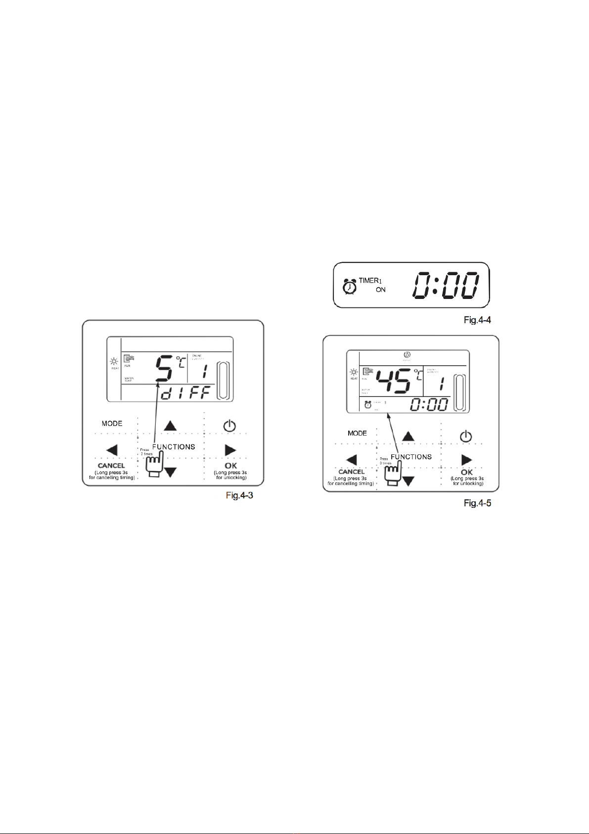
Continuous press “FUNCTIONS” key for 4
times to enter temperature difference
setting, the LCD will display “diFF”. Press
the “▲” or “▼” key to adjust the
temperature difference, press “OK” key or
wait for 7 seconds to confirm and back to
the main page. During setting process
pressing “CANCEL” key to exit without
saving. The range of temperature difference
is 2-10 degree.
Check the stop and restart temperature
difference setting: Press “◄” or “►” key
under main page to check the difference
value which has been set.
3) Timing setting: 3 timing periods can be
set on the wire controller: Timer 1, Timer
2, Timer 3. These 3 timers can control
the main unit to be turned ON and OFF 3
times at most during a day.
Setting method: press “FUNCTIONS”
key under main page three times to enter
timing setting. Then the LCD will display
as the following:

At this time the hour of the clock will flash,
which means the current setting is the hour
of Timer 1 “On”, press the “▲” or “▼” to
adjust, press “►” key when finished, and
then the minute of the clock will flash, which
means the current setting is the minute of
Timer 1 “On”, press the “▲” or “ ▼ ” to
adjust, press “►” key when finished, the
LCD will display as the following
At this time the hour of the clock will
flash, which means the current setting
is the hour of Timer 1 “Off”, press the
“▲” or “▼” to adjust, press “►” key
when finished, and then the minute of
the clock will flash, which means the
current setting is the minute of Timing
1 “Off”, press the “▲” or “▼” to adjust,
press “►” key when finished, the LCD
will display as the following:
At this time the hour of the clock will
flash, it means the current setting is the
hour of the Timer 2 “On”.
And the follow setting method will be the
same as the Timer 1. Similarly, the setting
of Timing 3 is the same as this method.
After setting is finished, press “OK” key or
wait for
7 seconds to confirm the setting, and the
LCD will display the effective timing
information, as the following display:

Example of Timing setting:
Écran principal
Appuyez deux fois sur la touche FUNCTIONS pour
entrer dans l'interface du réglage de l'heure de
« Timer 1 On ».
Appuyez sur la touche "
▲
ou "
▼
pour régler le
chiffre de l'heure de « Timing 1 On » sur 07.
Appuyez sur la touche "
►
" pour entrer dans
l'interface de réglage des minutes de « Timer 1
Appuyez sur la touche "
►
" pour entrer dans
l'interface de réglage de l'heure de « Timer 1 Off » ;
réglez le chiffre de l'heure de « Timer 1 Off » sur
Si le réglage de
« Timer 1 »
n'est pas actif
après 7
secondes,
l'affichage
Appuyez sur la touche "
►
" pour entrer dans
l'interface de réglage des minutes de « Timer 1
Non
Si vous
appuyez sur la
touche OK
Si vous
appuyez sur la
►
No
n
Réglez bien l'heure d'allumage de
« Timer 1 » sur 07:10 et l'heure
d'extinction de « Timer 1 Off » sur
12:30, puis revenez à l'écran
principal.
Terminez le réglage de l'heure
d'allumage de « Timer 1 » sur
07:10 et l'heure d'extinction sur
12:30, et saisissez le réglage
de « Timer 2 ».
Les étapes de réglage de « Timer 2 » et « Timer 3 » sont les mêmes que pour « Timer
1 », puis après les réglages appuyez sur la touche OK ; les trois périodes de
programmation seront actives.
Oui
Oui
Main page
Press “FUNCTIONS” key twice to enter hour setting
interface of “Timer 1 On”
Press the “▲” or “▼” key to set the hour number of “Timing
1 On” to be 07
Press “ ► ” key to enter minute setting interface of
“Timer 1 On”, adjust the minute number to be 10
Press “ ►” key to enter hour setting interface of
“Timer 1 Off”, adjust the hour number of “Timer 1
Off” to be 12
“Timer 1” setting
failed, after 7
seconds, the page
shift to the main
page.
Press “ ► ” key to enter minute setting interface of
“Timer 1 Off”, adjust the minute number to be 30.
No
Whether press
“OK” key
Whether press “
► ” key
No
Successfully set the On time of “Timer
1” to be 07:10 and Off time of “Timer 1
Off ” to be 12:30, then back to the
main page.
Finish setting the On time of “Timer 1” to
be 07:10 and Off time to be 12:30, then
enter the setting of “Timer 2”.
The setting steps of “Timer 2” and “Timer 3” are the same as “Timer 1”, after setting all the settings
then press “OK” key, the 3 timing periods will be effective.
Yes
Yes

During any period of timing setting to press “OK” key , the timing periods which have been set
will be effective (only if the “On” and “Off” of one timing period have been set, the setting is
effective).
Check timing information: to check the timing which has been set, press “◄” or “►” key
under main page, the “ On ”and “ Off ” time of Timer1, Timer 2 and Timer3 will be displayed
in turns.
Cancel timing: press and hold “CANCEL” key for 3 seconds, then all the effective timing
periods will be cancelled.
NOTE
To avoid timing error, each period of timing should not be crossed. E.g.:

4. Set working mode (valid when wire controller set to 2,3,4)
Press “MODE” key to enter the working mode setting when the main unit is off power. Press the
“MODE” key to adjust, press “OK” key or wait for 7 seconds to confirm and back to the main
page; during setting process pressing “CANCEL” key to exit without saving. The controller will
show different working mode when it is applied to different main unit. See fig.4-9.
NOTE
Working mode setting is valid only when the unit is power off. “COOL” and “HOT WATER” are not
avaiable

5) Set clock
Press the “FUNCTIONS” key 4 times to enter clock setting. The hour of the clock will flash,
which means the current setting is the hour of the clock, press the “▲” or “▼” to adjust, press
“ ” key when finished, and then the minute of the clock will flash, it means the current
setting is the minute of the clock, press the “▲” or “▼” to adjust, press “ OK ” key when
finished or wait for 7 seconds to confirm. During the setting process pressing the “CANCEL”
key to exit without saving.
NOTE
To get the correct timing On and timing Off time, please correctly set the clock!

4.3 Check
1) Check function allows the user to check all the operating parameters, error and
protection information of the main unit.
2) Enter method: press and hold “FUNCTIONS” key for 3 seconds to enter check interface, as
the figure display:
3) Query :
Check icon
Main unit sequence number
Check
parameter
Check sequence
number
Table 4-1
Nº
Display content (Normal display)
0
Mailing address
1
Network address or Remote address
2
The ability to dial
3
Operation capacity of indoor unit.
4
Operation capacity of outdoor unit.
5
Setting temp.
6
Water inlet temp.
7
Water outlet temp.
8
Water temp.in tank
9
Condenser pipe temp.T2
10
Condenser pipe temp.T2B
11
EXV opening
12
The temperature difference of auto-restarting
13
The cycle of auto-restarting
14
Last one error or protection
15
Last second error or protection
16
Last third error or protection

5. Error
handling
When the unit has error or protection, “ ” icon will flash. Press and hold “SET” key for 3
seconds to enter check status and then press the “▲” or “▼” key to check the unit of 0-15#. If
the “error” icon is on, it means the corresponding unit has error or protection
at that time. The last 3 error or protection codes of the unit can be checked. The error icon
will disappear if the error or protection is cleared.
Error code list (when the wire controller set to 1).
Table 5.1
NOTE
dF : defrost operation
d0 : oil return operation
dF and d0 are normal opration, not error.


Table of contents
Other Frigicoll Controllers manuals
Popular Controllers manuals by other brands

Danfoss
Danfoss AMV 110 NL AQT datasheet

Overland Storage
Overland Storage NEO 2000e Remove & Replace Instructions

Isimet
Isimet DLA Series Installation, Operations, Start-up and Maintenance Instructions

BBQ Guru
BBQ Guru Pitminder NanoQ II user guide

CD Automation
CD Automation CD3000S 1PH user manual

ICP DAS USA
ICP DAS USA WinPAC-8000 Series quick start guide