4 / 29 FRITZMEIER Umwelttechnik GmbH & Co. KG V1.6
ISARIA®Introduction
1 Introduction
We are glad you have opted for one of our products. We wish you flawless and successful
operation.
ISARIA®sensor system was especially developed to exactly determine the nutrient condition of
crops and for optimising site-specific fertilization.
The measuring process allows it to be used regardless of the time of day or weather. It is operated
centrally using a special terminal.
Any questions? We are looking forward to hearing from you.
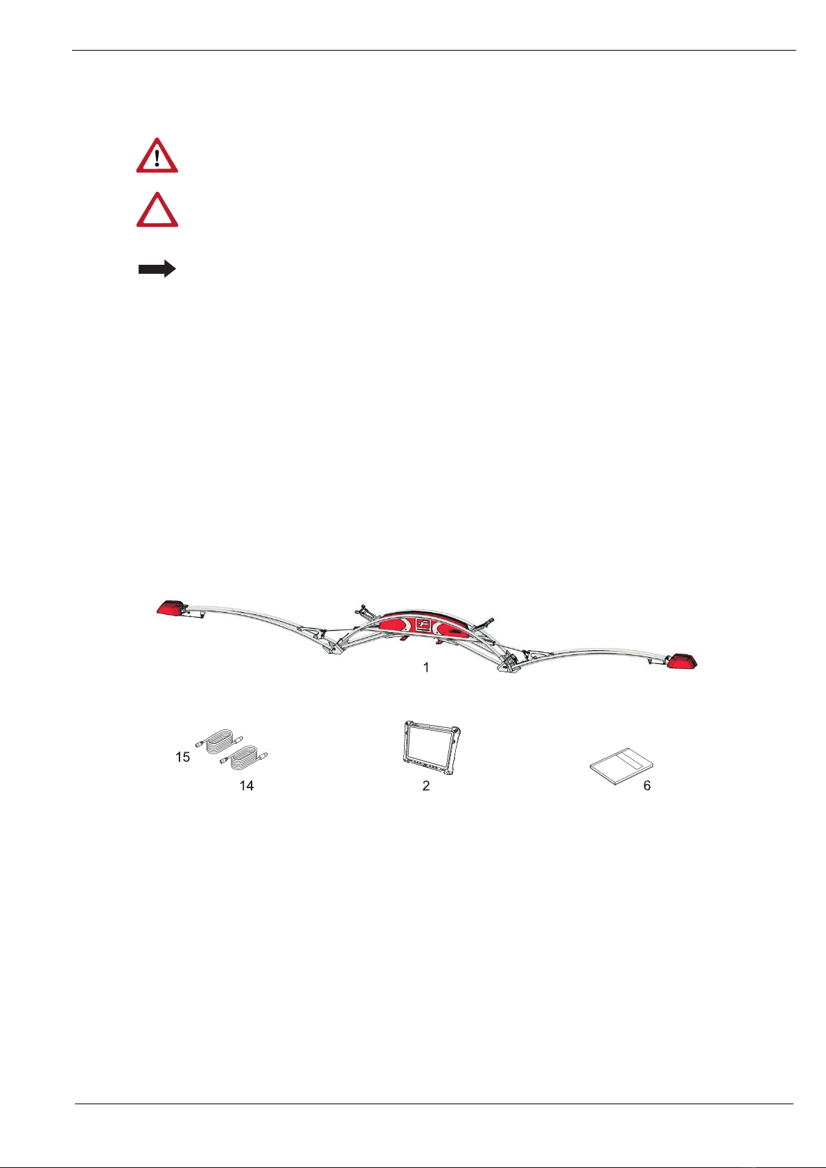
1.1 Product description
The data collection system in ISARIA®automatically saves all data required for the evaluation of
plant growth.
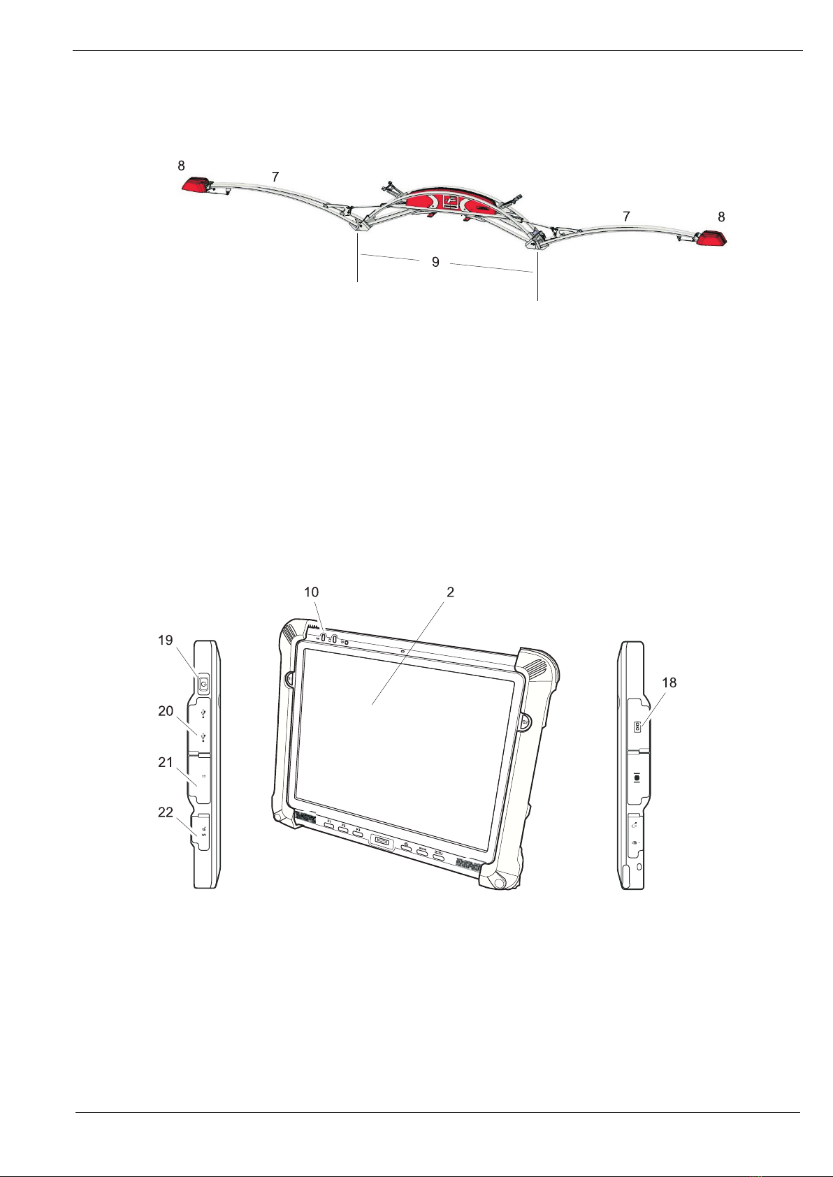
Two height-adjustable sensors supply data using a sensor-based process,
which forms the basis for calculating the nutrient condition of the crop. This enables the user to
determine the exact amount of fertilizer. The application of fertilizer can be determined to suit exact
needs while taking the yield potential of sub-fields into account.
When processing a job, geographical data recorded by the GPS receiver (Global Positioning
System) is assigned to the current measurement values and saved. All measuring data can be
exported to a removable storage medium in various formats (shape, txt, csv).
The yield data for the field can be used when calculating the amount of fertilizer.
The sensors, the GPS receiver and the motor control communicate with the operating terminal over
a Bluetooth interface. The sensor system is connected to the on-board management system on the
vehicle.
It is operated using a terminal with touch screen.
1.2 Notes on this manual
1.2.1 General information
This instruction manual contains all information and descriptions required to operate the system.
We have taken special care during the creation of this documentation. We are grateful to receive
any tips and suggestions you may have.
To facilitate traceability, we have included illustrations, schematic representations of the machine
and its assemblies to accompany the descriptions.
FRITZMEIER Umwelttechnik GmbH & Co. KG
Dorfstrasse 7
D-85653 Großhelfendorf Germany
Telephone +49 (0) 8095 87339-400
Fax +49 (0) 8095 87339-472