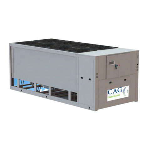
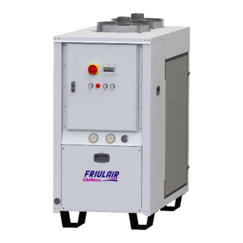
FRIULAIR PURESTREAM CHILLERS CWE-Q Series User manual

7425MUM753 Model: CWE-Q - Use and Maintenance Manual Rev. 15
WATER CHILLER
Model: CWE-Q
Use and Maintenance Manual

Editions Record
Code
Revision
Edition
Changes
7425MUM753 15 11/2020
Original instructions: ITALIAN
EN Translation of the original instructions

Dear Customer,
Thank you for the trust you have placed in us. Please read this manual carefully to obtain the
best performance from our product.
In order to avoid incorrect operating conditions and danger for the operators, it is essential
that you follow the instructions meticulously as well as the current accident-prevention laws
in the country of use.
Every chiller/heat pump in the CWE-Q series is tested thoroughly before being packed.
At this stage, checks are made to verify that there are no manufacturing defects and that the
machine performs correctly the functions for which it was designed.
This manual must be kept for future reference and is an integral part of the chiller you
have purchased.
Due to continuous technical development, we reserve the right to make the necessary
modifications without any obligation to give advance notice.
Do not hesitate to contact us if you have any problems or need more information.
The product identification plate, located on the side of the chiller, contains all essential
information about the machine.
You will have to give this data to the manufacturer, or reseller, whenever you request
information, spare parts, etc., during the warranty period.
Removing or tampering with the identification plate will void the warranty.
Warranty conditions:
The warranty is valid for 12 months from the machine being powered-up and no longer than 14
months from the delivery date. Any part which is recognised as being faulty at source shall be
repaired or replaced free of charge. This does not include transport costs, travel, room and board
for technicians. The warranty excludes any liability for direct or indirect damage to persons,
animals and/or property that are caused by incorrect use or inadequate maintenance and is
exclusively limited to manufacturing defects.
Repair under warranty is subject to compliance with the installation, use and maintenance
instructions contained in the "User manual and maintenance."
The warranty is considered void if the product is modified or tampered with in any way. When
making a warranty request, please supply the information available in the product identification
label.


CONTENTS
1SAFETY RULES...................................................................................................... 1
1.1 Definitions of the symbols used ...............................................................................................1
1.2 Warnings ..................................................................................................................................2
1.3 Proper use of the chiller ...........................................................................................................2
1.4 Instructions for using equipment under pressure conforming to PED Directive 2014/68/EU. 3
2OPERATION AND MAIN COMPONENTS............................................................... 4
2.1 Refrigerant circuit .....................................................................................................................4
2.2 Water circuit .............................................................................................................................5
2.3 Fans..........................................................................................................................................5
2.4 Condensation control ...............................................................................................................5
2.5 Control of the water temperature .............................................................................................5
2.6 Protecting the integrity of the machine ....................................................................................5
2.7 CWE-Q units: identification of the main components.............................................................. 6
2.7.1 Version with P3 TANF LSM BR ...............................................................................................6
2.8 Spare parts...............................................................................................................................7
3INSTALLATION....................................................................................................... 8
3.1 Transport ..................................................................................................................................8
3.1.1 Handling the unit with a forklift truck or pallet jack ..................................................................8
3.1.2 Lifting with belts and tubes.......................................................................................................8
3.2 Storage.....................................................................................................................................8
3.3 Place of installation ..................................................................................................................9
3.3.1 Installation spaces....................................................................................................................9
3.4 Water connections..................................................................................................................10
3.4.1 Recommended water system ................................................................................................10
3.4.2 Use of ethylene glycol as a winter anti-freeze.......................................................................11
3.4.3 Charging the water circuit ......................................................................................................11
3.5 Electrical connections ............................................................................................................12
3.5.1 Connecting a remote on/off switch and a remote alarm indicator light.................................12
4PRELIMINARY CHECKS AND START-UP........................................................... 13
4.1 Preliminary checks and preparation for the first start-up.......................................................13
4.2 Start-up...................................................................................................................................13
4.2.1 Start-up under critical conditions ...........................................................................................14
4.3 Turning off the unit .................................................................................................................14
5ELECTRONIC CONTROLLER .............................................................................. 15
5.1 Main functions of the electronic controller buttons and meanings of the icons .................... 15
5.2 Switching on/off......................................................................................................................16
5.3 Controlling water temperature................................................................................................16
5.4 Changing the cooling set point...............................................................................................18
5.5 Changing the heating set point ..............................................................................................18
5.6 Display of inputs and outputs.................................................................................................18
5.7 Alarms ....................................................................................................................................18
5.7.1 Displaying and resetting alarms.............................................................................................19
5.7.2 Table of alarm codes..............................................................................................................20
5.7.3 Displaying alarm history.........................................................................................................20
5.8 Parameters changing.............................................................................................................21
5.9 Setting the date and time .......................................................................................................21
5.10 Low water temperatures (<32°F//0°C)...................................................................................21

6SAFETY DEVICES ................................................................................................ 22
6.1 Calibration of the safety devices and type of rearm ..............................................................22
6.2 Rearming the high-pressure pressure switch........................................................................ 23
7OPERATING LIMITS............................................................................................. 24
7.1 Minimum water flow ...............................................................................................................26
8SEPR - SEASONAL ENERGY PERFORMANCE RATIO...................................... 27
9MAINTENANCE, INSPECTIONS AND PERIODIC CHECKS ................................ 28
10 TROUBLESHOOTING........................................................................................... 29
11 DISMANTLING THE CHILLER.............................................................................. 32
12 WATER DIAGRAMS ............................................................................................. 33
13 REFRIGERANT DIAGRAMS................................................................................. 34
14 DIMENSIONAL DRAWINGS ................................................................................. 35

1
7425MUM753 Model: CWE-Q - Use and Maintenance Manual Rev. 15
1
SAFETY RULES
1.1 DEFINITIONS OF THE SYMBOLS USED
Read this use and maintenance manual carefully before perfo
rming any repairs on the
chiller.
Warnings of a general character; risk of danger or possibility of damaging the machine,
pay particular attention to the phrase following this symbol.
Risk of electrical danger; the phrase highlights conditions that could be fatal. Follow the
instructions provided meticulously.
Risk of danger; component or system under pressure.
Risk of danger; component or system that can reach high temperatures during operation.
Risk of danger; it is absolutely forbidde
n to use water to extinguish fires near or on the
chiller.
Risk of danger; it is absolutely forbidden to operate the machine with the panel
open.
Service that can be performed by the machine’s operator, if qualified (1).
Water input connection point.
Water output connection point.
Dispose of each type of material in accordance with the requ
irements of the country of
use.
NOTE
Phrases to be emphasized that do not contain safety rules.

2
7425MUM753 Model: CWE-Q - Use and Maintenance Manual Rev. 15
This chiller has been carefully designed and constructed to be environmentally
friendly:
•Refrigerants without CFC;
•Expanded foam insulation without CFC;
•Energy-saving techniques;
•Reduced noise;
•The chiller and its packing materials are recyclable.
In order not to hinder our efforts, the user is required
to obey the simple ecological
warnings indicated by this symbol.
(1) These are persons with the experience, technical preparation and knowledge of
standards and regulations who are qualified to perform the necessary actions and able to
recognize and avoid possible dangers while handling, installing, using and maintaining
the machine.
1.2 WARNINGS
Only qualified persons may use and maintain electrically-powered equipment.
Before commencing maintenance operations ensure no parts of the machine are
live and it cannot be re-connected to the electrical power supply.
These chillers contain R410A refrigerant fluids. Service of the refrigerant circuit must be
performed by specialized personnel using proper tools.
Any modifications to the machine or related operating parameters not previously
verified and authorized by the Manufacturer may be hazardous and
will invalidate
the guarantee.
Do not use water to extinguish fires near or on the chiller.
1.3 PROPER USE OF THE CHILLER
CWE-Q units are monobloc water chillers with air-condensation.
They are intended for use in industrial process or air-conditioning systems requiring chilled
water.
Any other use is considered improper.
The manufacturer is not liable for damage resulting from inappropriate use; in all cases, the
user is liable for any resulting hazards.
Proper use requires conforming to the installation conditions and, in particular:
•Power voltage and frequency;
•Pressure, temperature and flow-capacity of the incoming water;
•Surrounding temperature.
The chiller has been tested and completely assembled. The user must only make the
connections to other systems, as described in the chapters that follow.

3
7425MUM753 Model: CWE-Q - Use and Maintenance Manual Rev. 15
1.4 INSTRUCTIONS FOR USING EQUIPMENT UNDER PRESSURE CONFORMING TO
PED DIRECTIVE 2014/68/EU
The proper use of equipment under pressure is an essential prerequisite for ensuring safety.
To this end, the user must proceed as follows:
•Use the equipment within the temperature range outlined in the operating limits on the
manufacturer's plate;
•Do not solder on the exchangers or refrigerant fluid pipes;
•Do not install the equipment in insufficiently ventilated rooms, areas exposed to
sources of heat or near inflammable substances;
•During operation, the equipment must not be subjected to vibrations that could cause
fatigue failures;
•Keep the documentation attached to the equipment (user manual, declaration of
conformity, etc.) for future reference;
•The maximum operating pressure shown on the manufacturer's plate must not be
exceeded. The user is responsible for fitting appropriate safety/control devices.

4
7425MUM753 Model: CWE-Q - Use and Maintenance Manual Rev. 15
2
OPERATION AND MAIN COMPONENTS
2.1 REFRIGERANT CIRCUIT
Operation of the CWE-Q chillers is based on a vapour compression cycle implemented within
the chiller circuit and made up of the following components - evaporator, compressor,
condenser and thermostatic expansion valve.
Evaporator: this is a braise-welded plate that exchanges heat between water and a
refrigerant fluid without their coming into contact with each other. It consists of corrugated
stainless steel plates braise-welded to each other with copper or of a copper pipe circuit
where the refrigerant flows, outside of which (in the iron mantle) the water to be cooled is
fluxed. The evaporator is protected against a lack of water by a differential pressure-switch
and against the formation of ice by an anti-freeze system managed by the chiller's electronic
controller.
Compressor: this compresses the vapours coming from the evaporator and sends them to
the condenser at a higher pressure. The CWE-Q series has scroll compressors which are
characterized by low noise and vibration levels. They are protected by thermal magnetic
circuit breakers and a temperature sensor inside the motor windings.
Condenser: heat exchanger with copper pipes and aluminum fins which enables heat
exchange between the refrigerant and the air. It condenses the refrigerant gas by transferring
condensation heat from the refrigerant gas to the air (which flows to the outside). As a result
high pressure liquid refrigerant is produced.
Thermostatic expansion valve: this reduces the pressure of the refrigerant liquid coming
from the condenser and sends it to the evaporator. This valve modulates the flow of
refrigerant in such a way as to maintain the constancy of the superheating of the gas exiting
to the evaporator under its various working conditions and, thus ensures that the flow of gas
entering the compressor contains no liquid.
Thanks to these components, the vapour-compression cycle works as follows: the
refrigerant liquid evaporates in the evaporator, chilling the water; the refrigerant vapours are
then aspirated from the compressor, which compresses them and sends them to the
condenser under high pressure; here, thanks to a flow of forced air from the fans, the high-
pressure refrigerant gas is cooled, making it condensed and undercooled.
The flow of refrigerant liquid then passes through the lamination valve (thermostatic
expansion valve), which drastically reduces its pressure: the refrigerant liquid returns to the
evaporator at a reduced pressure where it again evaporates, taking heat from the water.

5
7425MUM753 Model: CWE-Q - Use and Maintenance Manual Rev. 15
2.2 WATER CIRCUIT
The water circuit mainly consists of: evaporator, water strainer and hydraulic pipes.
The water flows first into the evaporator, where it is chilled, and then it is sent to the system.
A differential pressure switch on the evaporator checks that the flow of water is sufficient and
stops the compressors if the flow-capacity of the water does not ensure the good functioning
of the exchanger.
A fine mesh metal water strainer at the entrance to the evaporator catches any solid residues
that could damage the evaporator.
As option, units can be equipped with P3 pump, atmospheric tank, mechanical water level
switch and manual regulating bypass valve.
A manometer completes the unit's water circuit.
2.3 FANS
The fans force air through the condenser’s fins to remove the heat from the condensation of
the refrigerant gas, thus limiting the pressure inside the condenser.
CWE-Q chillers use external-rotor axial fans with thermal protection inside the motor winding.
2.4 CONDENSATION CONTROL
When the ambient air temperature decreases air flow cooling capacity increases
considerably, lowering the pressure within the condenser. The fans are switched off (or
slowed down in case of CA, CE and CL options) to reduce air flow and prevent the
condensation pressure going below the acceptable limits for correct chiller circuit operation.
With CA, CE and CL the fans are actually managed electronically by the condensation
pressure, enabling correct machine operation even when the external air temperature is very
low (see section 7Operating limits).
2.5 CONTROL OF THE WATER TEMPERATURE
The purpose of the chiller is to maintain the temperature of the water produced within a
desired interval as the load on the system varies; this is handled by an electronic controller
and a temperature probe that turn the compressor on and off appropriately (also see
paragraph 5.3 Controlling water temperature).
2.6 PROTECTING THE INTEGRITY OF THE MACHINE
In addition to controlling the temperature, the electronic controller uses pressure switches,
thermostats and timers to prevent and handle situations that could compromise the integrity
of the machine (also see Chapter 6Safety Devices).

6
7425MUM753 Model: CWE-Q - Use and Maintenance Manual Rev. 15
2.7 CWE-Q UNITS:IDENTIFICATION OF THE MAIN COMPONENTS
2.7.1 Version with P3 TANF LSM BR
Non ferrous atmospheric water circuit with P3 Pump , plastic tank, mechanical water level
switch and manual regulating valve.
04 High pressure switch
06 Compressor
08 Condenser
09 Fan
10 Filter
13 Gate Valve
14 Water strainer
17 Electronic controller
18 Evaporator
20 Liquid receiver (OPT)
22 Disconnector switch
23 High pressure manometer
24 Low pressure manometer
31 Safety valve
34 Sight glass
35 Thermostatic valve
37 Pressure transducer
45 Water manometer
61 Power input
68 On/off light
83 Pressure plug
85 Solenoid valve
90 Pump
91 Tank
94 Water filler
95 Water inlet
96 Water outlet
97 Drain

7
7425MUM753 Model: CWE-Q - Use and Maintenance Manual Rev. 15
2.8 SPARE PARTS
Spare parts list is printed on a dedicated sticker applied inside the chiller. On this sticker
each spare part is identified with its ID Number and related Spare Part Number. Here below
the cross reference table between ID Number and exploded drawings Ref. With their
description and quantity installed inside chillers.
NOTE To order the suggested spare parts or any other part, it is necessary to quote the
data reported on the identification plate.

8
7425MUM753 Model: CWE-Q - Use and Maintenance Manual Rev. 15
3
INSTALLATION
3.1 TRANSPORT
The units are provided with protective corner sections in cardboard and transparent film.
After checking that the packing is undamaged, position the unit near the installation site and
unpack it. The units can be handled using tubes and belts or a forklift truck.
Always keep the chiller vertical: turning it upside down can irreparably damage
several parts of the unit.
Handle with care. Violent falls can cause irreparable damage.
3.1.1 Handling the unit with a forklift truck or pallet jack
The centre of the machine is approximately its centre of gravity. In any case, when
handling the machi
ne with a forklift truck or pallet jack, always check its stability
before lifting.
3.1.2 Lifting with belts and tubes
Base supports that can accommodate bars to raise the units are provided.
Use steel tubes with a diameter of 1¼” and at least 0,12 in//3 mm thick and long enough to
project at least 9.85÷11,81 in//250÷300 mm from both sides of the machine's profile.
Lock the belts so that they won't slip off during lifting (see figure).
3.2STORAGE
Protect the machine from bad weather, even if packed.
Always keep the chiller vertical, even when in storage. Turning it upside down can irreparably
damage several parts of the unit.
If not used, the chiller can be stored packed in an enclosed place, free of dust, with a
maximum temperature of 50 °C/122°F and specific humidity of no higher than 90%.
The packing material is recyclable.
Dispose of each type of material in accordance with the re
quirements in
the country of use.

9
7425MUM753 Model: CWE-Q - Use and Maintenance Manual Rev. 15
3.3 PLACE OF INSTALLATION
The CWE-Q unit can be installed either inside or outside.
Attention! For CWE-Q100÷140 install the 4 rubber mats supplied loose and placed
inside the electrical panel, under the feet of the unit.
To determine the best place to install the unit, it is important to consider the following
aspects:
•The dimensions and source of the water pipes;
•The location of the electricity;
•The solidity of the support surface;
•Avoid any obstacles to the flow of the fan which could cause the recirculation of air to
the condenser;
•Avoid the possible reflection of sound waves: (do not install in narrow or tight spaces);
•Provide access for maintenance or repair (see paragraph 3.3.1 Installation spaces);
•The air temperatures in the area selected for installation (see Chapter 7 Operating
Limits).
Attention! If the machine is installed outside, it could find itself at a temperature
lower than 32°F//0
°C, when stopped; the formation of ice could damage
the ev
aporator. If you do not intend to drain the machine during the
winter, you must add anti-freeze to the water circuit (see paragraph 3.4.2
Use of ethylene glycol as a winter anti-freeze).
3.3.1 Installation spaces
To ensure the good functioning of the unit and access for maintenance, you must respect the
minimum installation space shown in the figure in this paragraph.
The exit of air from the fans must not be obstructed.
In any case, avoid all situations in which hot air can circulate between the output of the fans
and the intake of the machine.
The left or right side of the units can be placed against a wall.

10
7425MUM753 Model: CWE-Q - Use and Maintenance Manual Rev. 15
3.4 WATER CONNECTIONS
Connect the machine to the water pipes following the instructions located near its water
fittings (see figures).
Water input to the
machine
Water exit from the
machine
NOTE It is a good rule that the diameters of the arriving and departing pipes be not less
than the water fittings.
We recommend an extraordinary cleaning of the mechanical
water strainer after the machine has been running for the first
week (also see Chapter 9 Maintenance, inspections and
periodic inspections).
Diameters of the in/out water fittings
CWE-Q models 041 ÷ 068 100 140
60 Hz version 1½ ” NPT FF 2” VIC 2” ½ VIC
3.4.1 Recommended water system
The CWE-Q units can be provided with pump, tank, water strainer (standard), however it is
advisable to also equip the water circuit with:
•A mechanical water strainer and a check valve upstream from the charging tap;
•An air vent at the highest point of the system;
•A drain tap in the lowest point of the system;
•Manometers and thermometers at the machine’s water input and output to check its
functioning;
•Vibration damping joints on the pipes to avoid the transmission of vibration to the
system.
Attention! Never work
with an open flame near or inside the unit when making
connections to the water system.
Important! If the machine is stopped during the winter, you must empty the system
(or just the chiller) t
o avoid frost damage; any water remaining in the
pump must
be drained using the screw on the lower part of the pump
housing (see figure).

11
7425MUM753 Model: CWE-Q - Use and Maintenance Manual Rev. 15
3.4.2 Use of ethylene glycol as a winter anti-freeze
Instead of emptying the system in winter, you can charge the system with a mixture of water
and a suitable percentage of ethylene glycol, chosen as a function of the lowest expected
temperature of the outside air.
Percentages of ethylene glycol recommended
as a function of the expected temperature of the outside air
Outside air temperature [°C]
0
-5
-10
-12
-15
-20
Outside air temperature [°F]
32
23
14
10.4
5
-4
Percentage of ethylene glycol [%]
10
15
20
25
30
40
Attention! Maximum concentration of ethylene glycol allowed: 40%. For glycol
concentrations higher than 40%, contact our company's sales offices to make sure that
the mechanical seal and the pump motor are suitable for the type and concentration of
fluid loaded in the hydraulic system
3.4.3 Charging the water circuit
•Check that the drain taps are turned off;
•Open all the system’s vent valves;
•Turn on the system's shut-off devices;
•Start filling by slowly turning on the system's water-charging tap;
•When water starts coming out of the vent valves, close them and continue charging
until the manometer shows at least 1 bar; in case of water tank presence, charge fluid
up to maximum level;
•Bleed the pump using the venting screw on the Archimedes screw;
•Check the system level again;
•Check for any leaks by looking at the manometer and inspecting the circuit.
Pump drain screw
Pump venting screws

12
7425MUM753 Model: CWE-Q - Use and Maintenance Manual Rev. 15
3.5 ELECTRICAL CONNECTIONS
The machine must be connected to the electricity following the electrical diagram
and conforming to the current laws and regulations in the place of installation.
•The voltage, frequency and number of phases must conform to the data shown on the
machine's identification plate;
•The power supply voltage must not vary by more than ±10% from its nominal value;
•The frequency must not vary by more than ±1% from its nominal value (±2% for brief
periods);
•The imbalance between power phases must be <2%;
•Upstream from the electrical panel, install a differential switch (IDn=0,03A) (main
power switch) and slow-blow fuses with the specifications shown on the electrical
diagram;
•Use wires of the section shown on the electrical diagram.
Attention! Never change the internal electrical connections, as the warranty will be
immediately voided.
Important! Screw the wires solidly to the terminal strip of the cut-off switch and lock
the wire with a cable-gland.
Important! Make the cable entering the machine enters the cable-gland from below:
this prevents rain from dripping inside the machine.
Important! The earth conne
ction is mandatory: connect the earth wire to the
terminal provided in the electrical panel.
The ground wire must be longer than the other wires so that it will be the last one to be pulled
if the device holding the cable loosens.
3.5.1 Connecting a remote on/off switch and a remote alarm indicator light
A remote on/off switch can be connected to terminals in the electrical panel: there are 24V
between these two terminals.
An alarm indicator light can be connected to terminals (volt-free) in the electrical panel.
Consult the electrical diagram.

13
7425MUM753 Model: CWE-Q - Use and Maintenance Manual Rev. 15
4
PRELIMINARY CHECKS AND START-UP
4.1PRELIMINARY CHECKS AND PREPARATION FOR THE FIRST START-UP
Before starting up the unit, it is a good idea to do the following:
•Check that the water shut-off valves are open;
•Check that the pressure shown on the manometer with the pumps stopped is at least
1 bar (for closed water systems); in case of water tank presence, charge fluid up to
maximum level;
•Check that the surrounding temperature is in the range for the machine to function
(see Chapter 7Operating Limits);
•Check that the cut-off on the electrical panel of the machine is open (0 position);
•Check that the mains voltage matches the voltage on the machine's identification
plate with a tolerance of ±10%;
•Close the main power supply switch;
•Close the cut-off switch on the machine's electrical panel (I position).
This puts the machine under voltage without starting it up.
Attention! Apply voltage to the machine at least two hours before start-up to give
the heating elements in the compressor housing time to heat the oil
inside.
Attention! Our company reserves the right of not recognizing the warranty in
case of premature breaking down of the compressor, if it is
established that this operation is not normally executed by the
installer / user of the plant.
The heating elements limit the quantity of refrigerant dissolved in the oil and prevent the oil
from migrating when the compressors start.
Before start-up, check that the temperature of the lower part of the compressors is at least
50-59°F [10-15°C] higher than the surrounding temperature.
4.2 START-UP
To proceed to start-up:
1. Press key for 4 seconds. The led will flash and turn off, the chiller will switch on;
Electronic controller

14
7425MUM753 Model: CWE-Q - Use and Maintenance Manual Rev. 15
2. Check that the alarm symbol does not light up on the electronic controller;
Attention!At the first start-up there could be an alarm for an incorrect sequence
of the R-S-T phases, indicated by the initials AL27.
This safety system prevents the compressor from turning in the wrong direction.
Note: the phase sequence relay inside the electrical panel must have both LEDS lit to
confirm the correct electromagnetic field.
In this case, turn on the main power supply switch upstream from the
machine and reverse the two phases immediately downstream from the
main switch.
Attention! Never reverse the wires downstream from the main switch on
the electrical panel because doing so risks changing the correct
sequence of other devices, such as, for example, the pump and
fans.
Repeat the steps from point 1.
3. Check that the pump has started (the pump icon lights up) and check the water pressures
upstream and downstream from the machine on the manometers previously installed;
4. Wait for the electronic controller to verify that the water flow is constant through the signal
from the differential pressure-switch; if the differential pressure-switch intervenes (alarm
code AL03), vent the system, check that the shut-off taps and the functioning of the pump
are turned on. Reset the alarm following the procedure in paragraph 5.7.1 Displaying
and resetting alarms;
5. Wait for the compressors to start.
4.2.1 Start-up under critical conditions
The consequence of starting up under critical conditions could be the intervention of the high-
pressure pressure switch (to rearm the high-pressure pressure switch, see paragraph 6.2
Rearming the high-pressure pressure switch).
To overcome this problem, you will have to reduce the thermal load on the machine by
shutting off some of the uses or, if this is not possible, by reducing the flow of water into the
evaporator: partially close the output tap from the chiller and restart the machine.
Operate the chiller under these conditions until the water temperature gradually returns
within operating limits; then, you can turn on the tap completely.
4.3 TURNING OFF THE UNIT
For turn off the controller, press key for 4 seconds The led will flash and turn on, the
chiller will switch off (see paragraph 5.2 Switching on/off).
Attention! It is important not to turn the unit off using the main power supply switch
or the cut-off on the machine's electric
al panel because this would not
provide for the delayed power-off of the pump regarding the power-off of
the compressors, with the risk of damaging the ev
aporator; in addition, it
would prevent the functioning of the heating ele
ment in the compressor
housing.
This manual suits for next models
4
Table of contents
Other FRIULAIR Chiller manuals
Popular Chiller manuals by other brands

SMC Networks
SMC Networks HRZ001-L Operation manual

Trane
Trane CGWH 115 Installation operation & maintenance

Carrier
Carrier AquaEdge 23XRV Start-up, operation and maintenance instructions

Elkay
Elkay ERS1-1D Installation, care & use manual

York
York YZ Engineering guide

Daikin
Daikin EWAD-D-S Series Installation, operation and maintenance manual