manuals.online logo
Brands
  1. Home
  2. •
  3. Brands
  4. •
  5. Frontgate
  6. •
  7. Patio Furniture
  8. •
  9. Frontgate 140180B User manual

Frontgate 140180B User manual

1

F R O N T G A T E®
O U T F I TT IN G A M E R I CA ' S F I N E S T H O ME S
®


































Please read these instructions thoroughly to familiarize yourself with the process prior to
assembly.


First PREPARE your work
area


1.Openyourcartoncarefully,makingsurenottoscratchanyoftheparts.(Youhavemostlikelycompletedthisstepif
youhavetheseinstructionsinfrontofyou.)

2.Removeeachpartfromyourcartonandplaceitonasoftsurfacetoprotectitfrombeingscratched.

3.AfterALLthepartshavebeenremoved;spreadthecartonoutonthegroundtoprovideacleansurfacetoworkon.
(Orusealargeblanket.)

4.Removeallpackingmaterialfromthepartsandhardware.

5.Organizeyourpartsandhardwarebytypeandthencheckthemagainstthemasterlistonpage2tomakesureyou
havereceivedeverything.

6.Afteryouhavepreparedalltheparts,proceedtotheAssemblyInstructionsonpage3.
Tools Needed:AllenKey(Includedwithhardware)
SuppliesNeeded:EnoughSmallStones(Pebbles)orSandtofilltheinsideofthebasebottom.A
minimumof220lbsisrequired. Thismustbepurchasefromyourlocalhardwarestoreorlandscape
supplycompany.

Toprovidearustfree
product,theframeofthis
umbrellaismadeof
Aluminum.Aluminumisa
relativelysoftmaterial,so
pleasebecarefulnottoover
tightenyourhardware.We
alsorecommendthatyou
occasionallycheckthebolts
onyourumbrellatomake
suretheyaretightasthey
mayloosenovertime.

140180B NAPA SIDE MOUNT 10ft SQUARE UMBRELLA
with 140189 UMBRELLA BASE
2



PARTSLIST
Ref#NameDrawingQty
AUMBRELLA

1PC
BUMBRELLAMOUNT1PC
CBASEBOTTOM

1PC
DBASETOP

1PC
E‐1UMBRELLAMOUNT
BOLTS4PCS
E‐2UMBRELLAMOUNT
WASHERS4PCS
FCOLLAR
1PC
GROTATIONHANDLE1PC
HPIVOTTUBEFOR
ROTATIONHANDLE1PC
I‐1ROTATIONHANDLE
BOLT2PCS
I‐2ROTATIONHANDLE
WASHER2PCS
JCRANKHANDLE
1PC
KWHEELADJUSTING
TOOL1PC
LSHIPPINGCOVER

1PC
MALLENKEY
1PC
3


I. ASSEMBLY INSTRUCTIONS
1. PLACE the BASE BOTTOM (C) on your work
area. See Diagram 1.
Diagram 1
2. FILL the BASE BOTTOM (C) with a HEAVY
medium such as SMALL STONES (PEBBLES) or
SAND. (This must be purchase from your local
hardware store or landscape supply company.) See
Diagram 2.
NOTE: A MINIMUM of 220 lbs is required to operate
your umbrella safely.
Diagram 2
3. AFTER the BASE BOTTOM (C) has been filled,
PLACE the BASE TOP (D) on top of the BASE
BOTTOM (C). See Diagram 3.
This will now be referred to as the BASE
ASSEMBLY.
Diagram3
4. Place the UMBREALL MOUNT (B) on top of the
BASE ASSEMBLY. See Diagram 4.
Diagram 4

4


5. Place ONE UMBRELLA MOUNT BOLT (E-1) thru
ONE UMBRELLA MOUNT WASHER (E-2) and
THREAD it into the HOLE closest to you in the
UMBRELLA MOUNT (B). THREAD it in LOOSELY
with the ALLEN KEY (M). Do NOT TIGHTEN yet.
See Diagram 5.
Diagram 5
6. Repeat step 5 for the remaining THREE
UMBRELLA MOUNT BOLTS (E-1) and UMBRELLA
MOUNT WASHERS (E-2)
See Diagram 6.
Diagram 6
7. TIGHTEN all four FOUR UMBRELLA MOUNT
BOLTS (E-1) using the ALLEN KEY (M). See
Diagram 7.
Diagram 7
8. Slide COLLAR (F) over UMBRELLA MOUNT (B)
with the SMALLER END facing UP. See Diagram 8.
Diagram8

5


9. Carefully slide UMBRELLA (A) onto UMBRELLA
MOUNT (B). See Diagram 9.
Diagram9

10. LINE UP the ROTATION HANDLE (G) around
the lowest hole in the UMBRELLA (A) POLE, just
above the BASE ASSEMBLY. See Diagram 10a.
11. Slide the PIVOT TUBE (H) thru one side of the
ROTATION HANDLE and thru the UMBRELLA (A)
POLE. See Diagram 10b.
12. On the OPPOSITE side of the UMBRELLA (A)
POLE, SLIDE the ROTATION HANDLE BOLT (I-1)
thru the ROTATION HANDLE WASHER (I-2) and
then into the THREADED end of the PIVOT TUBE
(H). See Diagram 10c.
13. TIGHTEN with the ALLEN KEY (M). See
Diagram 10d.
Diagram10aDiagram10b

Diagram10cDiagram10d
14. Install the CRANK HANDLE (J) by SLIDING it
onto the CRANK MECHANISM, which is located on
the UMBRELLA (A) POLE. It should snap in place.
No hardware is needed. See Diagram 11.
Diagram11


6


II.OPERATINGINSTRUCTIONS
A. To RAISE and OPEN your UMBRELLA;
1. GRASP the LIFT HANDLE firmly.
2. DEPRESS the TRIGGER in the LIFT HANDLE with
your FINGERS. See close-up in Diagram 12a.
3. While keeping the BUTTON in the LIFT HANDLE
DEPRESSED, SLIDE the LIFT HANDLE UP until it
reaches the STOP. See Diagram 12b.
4. RELEASE the BUTTON in the LIFT HANDLE.
Diagram12aDiagram12b
5. TURN the CRANK HANDLE (J) CLOCKWISE until
your UMBRELLA is fully OPEN. See Diagram 13.
Diagram13

Your UMBRELLA can be ROTATED 360 degrees and TILTED to better protect you from the sun.
B. To ROTATE your UMBRELLA;
1. Lift up on the ROTATION HANDLE (G). See
Diagram 14a.
2. While holding the ROTATION HANDLE (G) up,
ROTATE the UMBRELLA by grasping the
UMBRELLA (A) POLE firmly and turning it. See
Diagram 14b.
Diagram 14a Diagram 14b
3. When you reach the desired position, lower the
ROTATION HANDLE (G) to lock the POLE (A) in
place. See Diagram 15a & b.
Diagram 15a Diagram 15b

7


C. To TILT your UMBRELLA:
1. With the UMBRELLA FULLY OPEN, DEPRESS
the BUTTON in the LIFT HANDLE. See
Diagram 16.
2. While keeping the BUTTON in the LIFT HANDLE
DEPRESSED, SLIDE the LIFT HANDLE DOWN the
POLE until you reach your desired position. There
are several HOLES in the POLE (A) for you to lock
the LIFT HANDLE into. You must line up the LIFT
HANDLE with one of these holes or the LIFT
HANDLE may drop down when you let go. See
Diagram 16b.
Diagram 16a Diagram 16b
3. Release the BUTTON in the LIFT HANDLE. See
Diagram 17. It may be necessary to raise or lower
the LIFT HANDLE slightly to get the pin to line up
with the corresponding hole in the pole (A).
Diagram 17
D. To LOWER and CLOSE your UMBRELLA;
1. TURN the CRANK HANDLE (J) COUNTER
CLOCKWISE until the UMBRELLA is FULLY
CLOSED. See Diagrams 18a and 18b.
Diagram18aDiagram18b
2. DEPRESS the TRIGGER in the LIFT HANDLE with
your FINGERS. See close-up in Diagram 19a.
3. While keeping the BUTTON in the LIFT HANDLE
DEPRESSED, SLIDE the LIFT HANDLE DOWN as
far as it will go. The FABRIC part of the UMBRELLA
should now be next to the POLE. See Diagram 19b.
4. RELEASE the BUTTON in the LIFT HANDLE.
Diagram19aDiagram19b

8


5. SECURE your UMBRELLA to the POLE (A) using
the VELCRO TIES. ALWAYS keep it SECURED to
the POLE when not in use. See Diagram 20.
Diagram20

To make it easier to move your umbrella, the BASE ASSEMBLY comes equipped with RETRACTABLE WHEELS.
E. To extend the WHEELS in your BASE;
1. First CLOSE, LOWER & SECURE your
UMBRELLA as described in steps 1-5 in SECTION
IID on pages 7 & 8. See Diagram 21.
Diagram21

2. REMOVE all four WHEEL ADJUSTER CAPS by
carefully prying them up with your finger. See
Diagram 22a.
3. Place the WHEEL ADJUSTING TOOL (K) into the
WHEEL HOLE (previously covered by the WHEEL
ADJUSTER CAPS) closest to you. See Diagram 22b.
Diagram 22a Diagram 22b

4. Remove CRANK HANDLE (J) from CRANK
MECHANISM by pulling it straight off. See Diagram
23a.
5. Place CRANK HANDLE (J) onto WHEEL
ADJUSTING TOOL (K) in first hole. See Diagram
23b.
Diagram 23a Diagram 23b

9


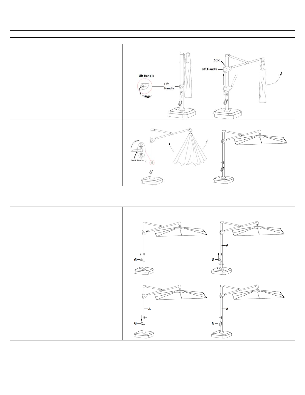
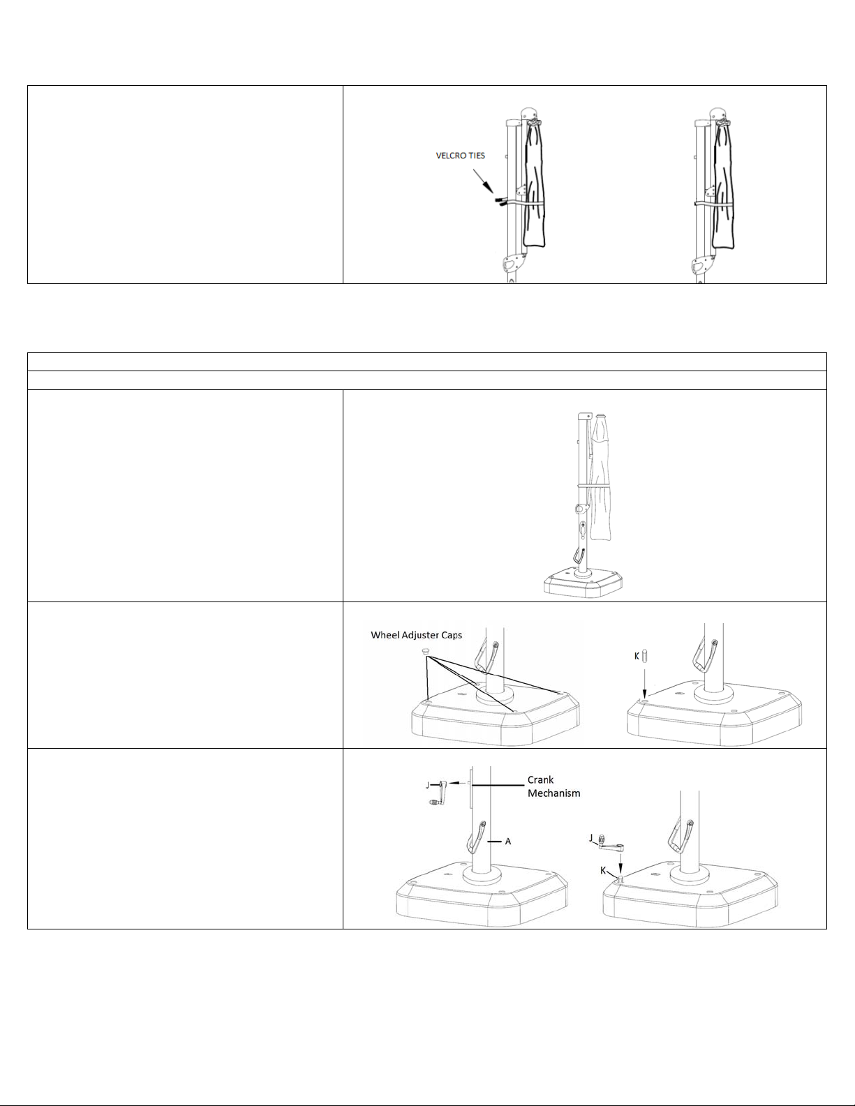
6. Rotate CRANK HANDLE (J) CLOCKWIZE until
the WHEEL protrudes from the BASE just far enough
to allow you to roll the BASE. See Diagram 24a
There should be a MINIMUM of ½” of the WHEEL
ADJUSTER TOOL (K) sticking out between the BASE
and the CRANK HANDLE. See Diagram 24b.
Diagram 24a Diagram 24b
7. Remove the CRANK HANDLE (J) and WHEEL
ADJUSTER TOOL (K) and install them in the next
closest WHEEL HOLE. See Diagram 25a.
8. Repeat step 6 for this wheel. See Diagram 25b.
9. Repeat step 7 & 6 for the remaining two WHEELS.
Diagram25aDiagram25b

10. Roll your UMBRELLA to its new location. See
Diagram 26a
11. RETRACT the last wheel you lowered by turning
the CRANK HANDLE (J) COUNTER CLOCKWIZE
until it has fully retracted. Make sure the bottom of the
base is resting on the ground an no longer on the
wheel. See Diagram 26b.
12. Remove the CRANK HANDLE (J) and WHEEL
ADJUSTER TOOL (K) and install them in the next
closest WHEEL HOLE. See Diagram 26c.
13. Repeat steps 12 & 11 from this section to retract
the remaining wheels.
14. REPLACE all four WHEEL ADJUSTER CAPS by
PRESSING them back into their original HOLES.
See Diagram 26d.
-end-
Diagram 26a Diagram 26b

Diagram 26c Diagram 26d
 
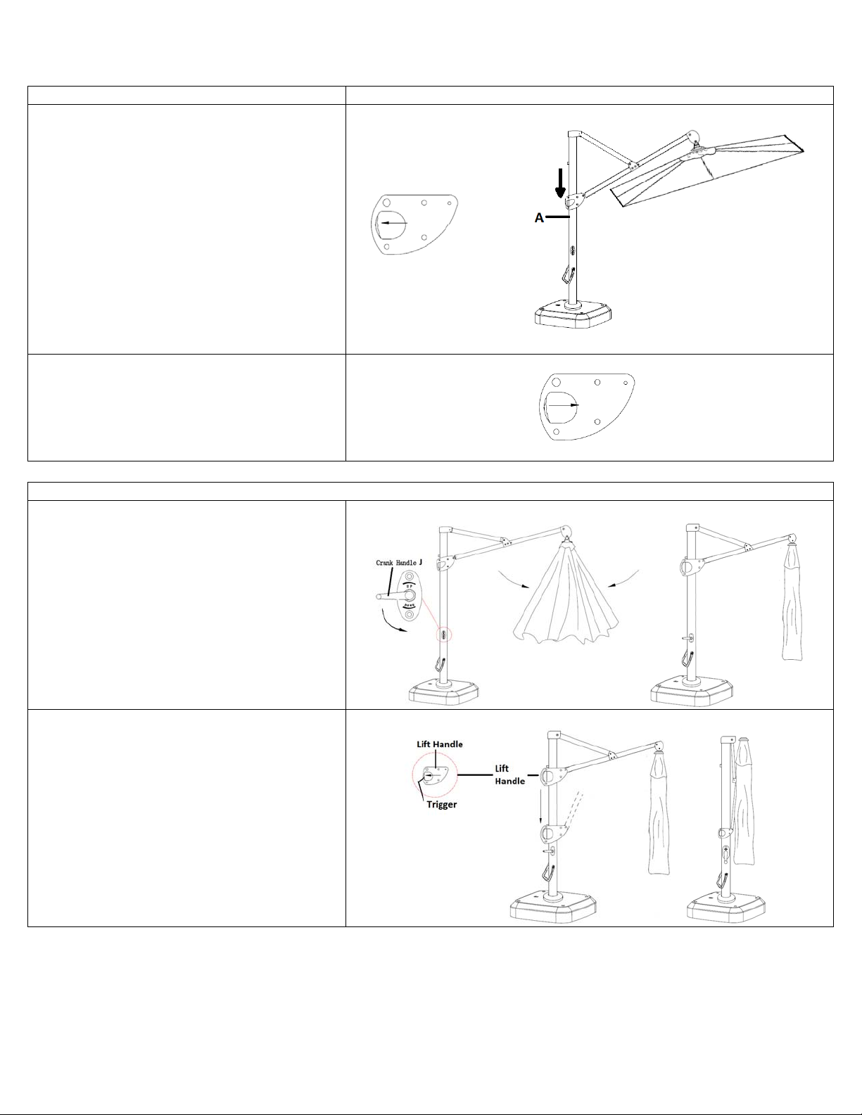
Your umbrella came with a SHIPPING COVER (L) for added protection during SHIPPING. Feel free to use this cover, but it is not
recommended for outdoor use since the fabric is not designed for prolonged exposure to UV rays.
If you use furniture covers, use only SOFT (cloth) backed covers and always make sure your furniture is clean
and
COMPLETELY dry before
covering. (Remember that dark wet places may lead to
mold.)
Cleaning Instructions: Clean with a mild soap and warm water (Do not use abrasive cleaners or
scrubbers/brushes.)
Please contact one of our Product Specialists for assembly assistance or questions at 1-800-537-8484 or email [email protected].
Specialists are available weekdays 8:00 a.m. to 8:00 p.m. EST and Saturday 9:30 a.m. to 6:00 p.m.


This manual suits for next models

1

Other Frontgate Patio Furniture manuals

Frontgate 64445 Installation instructions

Frontgate

Frontgate 64445 Installation instructions

Frontgate 68286A Installation instructions

Frontgate

Frontgate 68286A Installation instructions

Frontgate CASSARA 20128A User manual

Frontgate

Frontgate CASSARA 20128A User manual

Frontgate Carlisle 28019 User manual

Frontgate

Frontgate Carlisle 28019 User manual

Frontgate Kingston 166188A NAT User manual

Frontgate

Frontgate Kingston 166188A NAT User manual

Popular Patio Furniture manuals by other brands

Sunnydaze Decor MERANTI FRN-732 manual

Sunnydaze Decor

Sunnydaze Decor MERANTI FRN-732 manual

Agio 1031541 Assembly instructions

Agio

Agio 1031541 Assembly instructions

Broyhill LEGACY A206005300 Assembly instructions

Broyhill

Broyhill LEGACY A206005300 Assembly instructions

Costway OP70821 user manual

Costway

Costway OP70821 user manual

for Living A702000500 Assembly instructions

for Living

for Living A702000500 Assembly instructions

kingsley-bate WS-59 Assembly instructions

kingsley-bate

kingsley-bate WS-59 Assembly instructions

Tuuci MAX TILT CANTILEVER Assembly & operating instructions

Tuuci

Tuuci MAX TILT CANTILEVER Assembly & operating instructions

One Stop Gardens 91761 Assembly instructions

One Stop Gardens

One Stop Gardens 91761 Assembly instructions

paramondo interpara installation instructions

paramondo

paramondo interpara installation instructions

Extremis Acacia manual

Extremis

Extremis Acacia manual

Bambrella LEVANTE SIDE WIND instructions

Bambrella

Bambrella LEVANTE SIDE WIND instructions

Sunnydaze Decor OP-169-COMBO manual

Sunnydaze Decor

Sunnydaze Decor OP-169-COMBO manual

modway EEI-2301 quick start guide

modway

modway EEI-2301 quick start guide

Sunjoy S-UM248PST-A Assembly instruction

Sunjoy

Sunjoy S-UM248PST-A Assembly instruction

Coolaroo MINDIL 3M ROUND Assembly Guide and Operating Instructions

Coolaroo

Coolaroo MINDIL 3M ROUND Assembly Guide and Operating Instructions

Costway HW63800 Assembly instructions

Costway

Costway HW63800 Assembly instructions

Hanover San Marino SMAR4PCFP-TAN-WG owner's manual

Hanover

Hanover San Marino SMAR4PCFP-TAN-WG owner's manual

Seasons Sentry UMB-546980CL Assembly, care & use manual

Seasons Sentry

Seasons Sentry UMB-546980CL Assembly, care & use manual

manuals.online logo
manuals.online logoBrands
  • About & Mission
  • Contact us
  • Privacy Policy
  • Terms and Conditions

Copyright 2025 Manuals.Online. All Rights Reserved.