Thank you for your purchase of Frontgate’s 10’ Square Side Mount umbrella.
Please remo e all contents from the package, inspect and re iew checklist for
all parts. CAUTION: To reduce personal injury and damage to your umbrella,
read and follow this Assembly and Operation information.
110
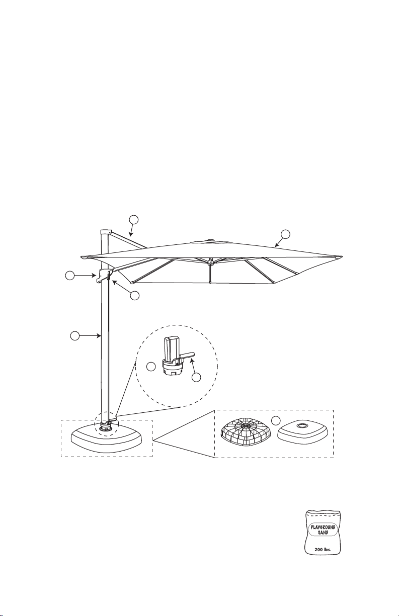
Base Parts Boxed Separately
D
F
H
G
E
Base Shell Base Lid
A
B
C
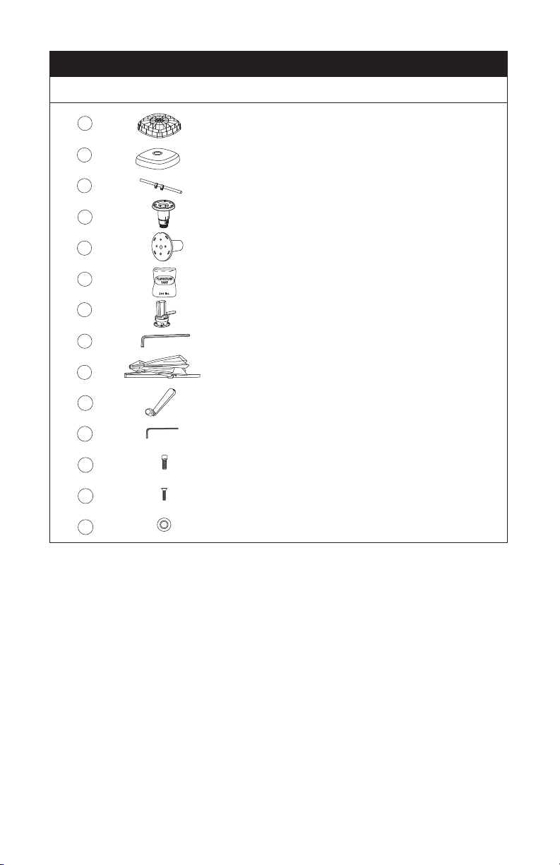
C H E C K L I S T :
A - Base Shell and Base Lid E - Removable Crank Handle
B - 360° Rotating Hub F - Main Frame Grip Handle
C - Foot Pedal G- Main Arm
D-Main Frame H- Canopy
REQUIRED FOR ASSEMBL :
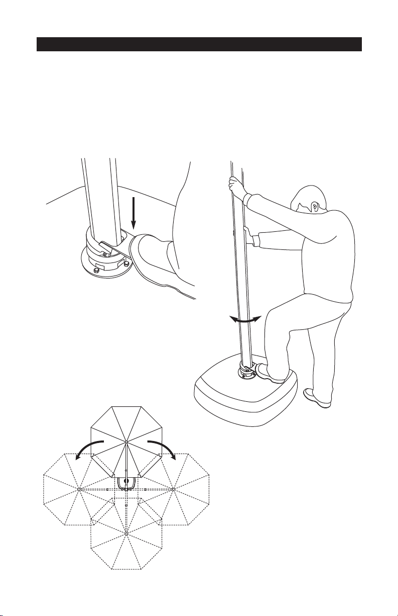
• 200 lbs. playground sand (not included).
Please contact one of our Product Specialists for assembly assistance or questions
at 1-800-537-8484 or email ps@frontgate.com. Specialists are available weekdays
8:00 a.m. to 8:00 p.m. EST or Saturday 9:30 a.m. to 6:00 p.m.
Our Quality Commitment
At Frontgate, our primary ocus is quality.
We guarantee that every product we sell
will stand up to the supreme test — our
customers’ satis action.
Our One-Year Guarantee lets you put any
Frontgate product to the test. I or any
reason you are not satis ied, simply return
it within 90 days and we’ll replace it or
re und the cost o the item (excluding
Shipping and Processing ees). In addition,
we will repair or replace any product or a
ull year rom the date o purchase.
Please note: Any items that are
monogrammed, customized or made-to-
order cannot be returned or exchanged
unless damaged or de ective.
All returned items must be in their original
packaging and in the condition in which
they were received. Please wrap your item
care ully; package and ship it so that
damage does not occur. Follow the return
process instructions on the pack slip or
visit our website or more in ormation
regarding returns.