Frymaster FPH-14/7 Manual

FPH-14/7
OPERATOR’S
GUIDE
ELECTRIC
FRYERS
WITH
BUILT-IN
FILTRATION
FPH-14/7
Frymaster
L.L.C.,
8700
Line
Avenue,
P.
O.
UOX
o
iuuu,
omibvci
318-865-1711
FAX
318-862-2394
Printed
in
U.S.A.
SERVICE
HOTLINE
1-800-551-8633
ISO
REGISTERED
QUALITY
SYSTEM
71135-1000
Price
$4.00
819-5309
9/93

FOR
YOUR,
SAFETY,
DO
NOT
STORE
OR
USE
GASOLINE
OR
OTHER
FLAMMABLE
VAPORS
AND
LIQUIDS
IN
THE
VICINITY
OF
THIS
OR
ANY
OTHER
APPLIANCE.

TABLE
OF
CONTENTS
SECTION
PAGE
NO.
1.
PARTS
ORDERING/SERVICE
INFORMATION..
2.
IMPORTANT
INFORMATION.1
3.
INSTALLATION
INSTRUCTIONS.1
4.
ELECTRICAL
SERVICE
CONNECTIONS.2
5.
OPERATING
INSTRUCTIONS.4
6.
DRAINING
AND
CLEANING
INSTRUCTIONS.5
7.
SHUTTING
FRYERS
OFF.5
8.
COMPUTER
MAGIC
III
OPERATING
INSTRUCTIONS.6
9.
COMPUTER
MAGIC
III
PROGRAMMING
INSTRUCTIONS.8
10.
ACCESSORIES.11
11.
PARTS
LIST.12
12.
FOOTPRINT
II
PARTS
LIST.13
13.
TROUBLESHOOTING
GUIDE.14
14.
PREVENTIVE
MAINTENANCE.16
15.
FOOTPRINT
II
FILTER
OPERATING
INSTRUCTIONS.17
16.
FILTER
SYSTEM
TROUBLESHOOTING.19
17.
FRYER
SPECIFICATION
SHEET.20
18.
WARRANTY.21
1.
PARTS
ORDERING/SERVICE
INFORMATION
Parts
orders
must
be
placed
directly
with
your
local
Frymaster
Parts
Distributor.
To
help
speed
up
your
order,
the
following
information
is
required:
information
may
also
be
obtained
by
calling
the
Fry-
master
Service
Department.
When
calling,
please
have
the
following
information
available.
1.
Model
Number:_
2.
Serial
Number:_
3.
Voltage:_
4.
Item
Part
Number:_
5.
Quantity
Required:_
NOTE:
A
list
of
Frymaster
Parts
Distributors
was
included
with
the
fryers
when
shipped
from
the
fac¬
tory.
If
you
do
not
have
access
to
this
list,
please
contact
the
Service
Department
at
Frymaster
1-800-
551
-8633
or
1
-318-865-1711.
Service
information
may
be
obtained
by
calling
your
local
Factory
Authorized
Service
Center.
A
list
of
these
agencies
is
packed
with
your
fryer.
Service
1.
Model
Number:_
2.
Serial
Number:_
3.
Voltage:_
4.
Nature
of
service
problem
and
symptoms.
5.
Any
other
information
that
may
be
helpful
in
solving
your
service
problem.
PARTS
ORDERING/SERVICE
INFORMATION
CANADA
—
Garland
Commercial
Ranges,
Ltd.,
1177
Kamato
Road,
Mississauga,
Ontario
L4W1X4.
NOTE:
RETAIN
AND
STORE
THIS
MANUAL
IN
A
SAFE
PLACE
FOR
FUTURE
USE.
ADDITIONAL
COPIES
MAY
BE
OBTAINED
FROM
YOUR
AUTHORIZED
SERVICE
AGENCY.

2.
IMPORTANT
INFORMATION
OPERATING,
INSTALLATION,
AND
SERVICE
PERSONNEL
Operating
information
for
FRYMASTER
equipment
has
been
prepared
for
use
by
qualified
and/or
author¬
ized
operating
personnel
only.
All
installation
and
service
on
FRYMASTER
equip¬
ment
must
be
performed
by
qualified,
certified,
li¬
censed,
and/or
authorized
installation
or
service
personnel.
Service
may
be
obtained
by
contacting
the
FRY¬
MASTER
FACTORY
SERVICE
DEPARTMENT,
Factory
Representative,
or
local
Factory
Authorized
Service
Center.
DEFINITIONS
QUALIFIED
AND/OR
AUTHORIZED
OPERATING
PERSONNEL
Qualified
or
authorized
operating
personnel
are
those
who
have
carefully
read
the
information
in
this
manual
and
have
familiarized
themselves
with
the
equipment
functions
or
have
had
previous
experi¬
ence
with
the
operation
of
equipment
covered
in
this
manual.
QUALIFIED
INSTALLATION
PERSONNEL
Qualified
installation
personnel
are:
individuals,
a
firm,
corporation,
or
a
company
which
either
in
per¬
son
or
through
a
representative
are
engaged
in,
and
are
responsible
for
the
installation
of
electrical
wiring
from
the
building
electric
meter,
main
control
box,
or
service
outlet
to
the
electrical
appliance.
Qualified
installation
personnel
must
be
experienced
in
such
work,
be
familiar
with
all
electrical
precautions
re¬
quired,
and
have
complied
with
all
requirements
of
state
and
local
codes.
Reference:
All
electrically
op¬
erated
appliances
must
be
electrically
connected
and
grounded
in
accordance
with
local
codes,
or
in
the
absence
of
local
codes,
with
the
latest
edition
of
the
United
States
National
Electrical
Code
ANSI/N.F.P.A.
No.
70.
In
CANADA,
with
Canadian
Electrical
Code
Part
1,
CSA-C22.1.
QUALIFIED
SERVICE
PERSONNEL
Qualified
service
personnel
are
those
familiar
with
FRYMASTER
equipment
and
have
been
authorized
by
THE
FRYMASTER
CORPORATION.
All
author¬
ized
service
personnel
are
required
to
be
equipped
with
a
complete
set
of
service
parts
manuals
and
stock
a
minimum
amount
of
parts
for
FRYMASTER
equipment.
A
list
of
Frymaster
Factory
Authorized
Service
Cen¬
ters
was
included
with
the
fryer
when
shipped
from
the
factory.
If
you
do
not
have
access
to
this
list,
please
contact
the
Frymaster
Customer
Service
De¬
partment,
using
the
number
listed
on
the
front
of
this
manual.
Failure
to
use
qualified
service
personnel
will
void
the
Frymaster
warranty.
SHIPPING
DAMAGE
CLAIM
PROCEDURE
For
your
protection,
please
note
that
the
FRYMAS¬
TER
equipment
was
carefully
inspected
and
packed
by
skilled
personnel
before
leaving
the
factory.
The
transportation
company
assumes
full
responsibility
for
safe
delivery
upon
acceptance
of
the
equipment.
What
to
do
rf
equipment
arrives
damaged:
1.
FILE
CLAIM
FOR
DAMAGES
IMMEDIATELY
—
Regardless
of
extent
of
damage.
2.
VISIBLE
LOSS
OR
DAMAGE
—
Be
sure
this
is
noted
on
the
freight
bill
or
express
receipt
and
is
signed
by
the
person
making
the
delivery.
3.
CONCEALED
LOSS
OR
DAMAGE
—
If
damage
is
unnoticed
until
equipment
is
unpacked,
notify
freight
company
or
carrier
immediately,
and
file
a
concealed
damage
claim.
This
should
be
done
within
fifteen
(15)
days
of
date
of
delivery.
Be
sure
to
retain
container
for
inspection.
FRYMASTER
DOES
NOT
ASSUME
RESPONSI¬
BILITY
FOR
DAMAGE
OR
LOSS
INCURRED
IN
TRANSIT.
3.
INSTALLATION
INSTRUCTIONS
PROPER
INSTALLATION
IS
ESSENTIAL
TO
EF¬
FICIENT
TROUBLE-FREE
OPERATION.
ANY
AL¬
TERATION
OF
THE
EQUIPMENT
VOIDS
THE
FRYMASTER
WARRANTY.
Before
installing
the
newly-arrived
equipment,
in¬
spect
it
carefully
for
visible
and
concealed
damage.
See
‘Shipping
Damage
Claim
Procedure”
in
Section
2
.
The
FPH14/7
fryer
accessory
package
contains
a
leg
and
caster
installation
instruction
sheet
for
installa¬
tion
of
legs
and/or
casters.
The
fryer(s)
may
be
laid
on
its
back
or
raised
with
a
small
floor
jack
to
install
legs
or
casters.
CAUTION:
Extreme
caution
MUST
be
exercised
to
prevent
damage
to
the
cabinet(s)
and
undercarriage.

FOR
UNITS
EQUIPPED
WITH
FRYMASTER
COMPUTERS
This
equipment
generates
and
uses
radio
frequency
energy;
and
if
not
installed
and
used
properly,
that
is,
in
strict
accordance
with
the
manufacturer’s
instruc¬
tions,
may
cause
interference
to
radio
and
television
reception.
It
has
been
type
tested
and
found
to
com¬
ply
with
the
limits
of
a
Class
B
computing
device
in
accordance
with
the
specifications
in
Subpart
J
of
Part
155
of
FCC
Rules,
which
are
designed
to
pro¬
vide
reasonable
protection
against
such
interference
in
a
residential
installation.
However,
there
is
no
guarantee
that
interference
will
not
occur
in
a
particu¬
lar
installation.
If
this
equipment
does
cause
interfer¬
ence
to
radio
or
television
reception,
which
can
be
determined
by
turning
the
equipment
off
and
on,
the
user
is
encouraged
to
try
to
correct
the
interference
by
one
or
more
of
the
following
measures:
If
necessary,
the
user
should
consult
the
dealer
or
an
experienced
radio/television
technician
for
additional
suggestions.
The
user
may
find
the
following
booklet
prepared
by
the
Federal
Communications
Commission
helpful:
“How
to
Identify
and
Resolve
Radio-TV
Interference
Problems."
This
booklet
is
available
from
the
U.
S.
Government
Printing
Office,
Washington,
DC
20402,
Stock
No.
004-000-00345-4.
4.
ELECTRICAL
SERVICE
CONNECTIONS
Service
connections
should
be
made
through
the
bottom
rear
portion
of
the
fryer
cabinet
by
means
of
an
approved,
flexible-metallic
or
rubber-covered
electrical
cable
and
quick-disconnect
plug.
This
con¬
nection
should
be
made
to
the
fryer
power
input
terminal
block.
If
rigid
or
flexible-metal
conduit
con¬
nections
are
required,
they
must
be
made
through
the
rear
portion
of
the
fryer
cabinet
to
the
fryer
power
input
terminal
block.
The
terminal
block
is
located
in
the
electrical
component
box
behind
the
control
panel
on
FPH-14/7.
CONNECTIONS
MUST
BE
MADE
BY
QUALIFIED
PERSONNEL
ONLY.
CAUTION:
The
fryer(s)
MUST
be
connected
to
the
voltage
and
phase
as
specified
on
the
rating
and
serial
number
plate
located
on
the
back
of
the
fryer
door.
To
deter¬
mine
the
proper
wire
size
and
amperage
service
per
fryer,
use
the
chart
on
Page
3,
“POWER
REQUIRE¬
MENTS.”
To
facilitate
cleaning
and
service,
it
is
recommended
that
the
fryer(s)
be
connected
to
the
external
power
source
by
means
of
a
UL
approved
quick-disconnect
plug.
CAUTION:
A
ground
wire
MUST
be
connected
to
the
GROUND
terminal
provided
near
the
input
power
terminal
block.
CAUTION:
The
following
cautions
should
be
adhered
to
when
connecting
the
fryer
to
an
emergency
cutoff
system:
■
Be
sure
that
each
fryer
is
connected
to
a
dedicated
set
of
contacts
in
the
emer¬
gency
cutoff
system.
■
Refer
to
electrical
handy
box
under
left
side
of
frypot.
Connection
terminal
block
is
located
inside
box.
Disconnect
jumper
wire
34C
and
replace
with
fire
cut-off
con¬
nection.
■
Do
not
attempt
to
connect
the
contacts
in
series.
■
Do
not
connect
more
than
one
fryer
to
each
set
of
contacts.
■
The
contacts
MUST
BE
normally
closed
contacts
that
open
during
the
emergency.
■
The
contacts
CANNOT
have
an
external
voltage
applied.
/
2

14KW
&
7KW
POWER
REQUIREMENTS
4.
ELECTRICAL
SERVICE
CONNECTIONS
*
“
7T
CO
b
1^01
x
x
CL
[sj
<
<
<
<
<
^<J)
O
o
^p
nP
Np
mlmm
wammr
iz
\—
co
wmmx
<
LU
_l
>
QE
LlJ
o
cn
■
>—
o
Ll_
Q_
CN
T
00
<
CL
X
<
UJ
LU
Xm
O
5?
<
CO
<
CO
<
CO
$
<
CO
<
X
^00
CD
CD
o
o
o
X
CO
LU
_J
CL
1—
LU
CD
Np
r-
CNJ
o
<
>
CL
ID
rD
CNJ
CN
<J)
CL
1
<
X
LU
X
CO
*
*
<
o
o
1—
O
o
CnI
Np
_J
00
CN
CN
o
O
nP
oo
\
\
>
C\l
CN
nP
O
oo
lO
■
©.
0)
Np
rD
_>\
Q_
■
Cl
■
D
0)
P
2
o
o
CD
O
.E
c
N
1”
CD
O
.E
o
^
CD
TO
CD
O
~o
C
TO
^
v
E
•
-
E
CO
L
-
o
o
CD
CD
CX
C/0
CD
N
CD
E
c
o
Q_
<L)
C
0
o
2
TO
O'
c
CL
O
0
w
o
O'
>
rtr
0
TO
0
o
-g
h-
O
<1>
L_
C
0-0
o
•
•-
o
c
o
0
.
>N
0
o
0
c
c
o
o
0
0
0
0
>N
0
Nt
TO
0
L_
*Z5
O*
0
±1
Z5
O
O
0
0
cnj
ro
*
o
3

5.
OPERATING
INSTRUCTIONS
AFTER
FRYER(S)
HAVE
BEEN
INSTALLED
AT
FRYING
STATION:
1.
To
level
fryers,
the
bottom
of
legs
can
be
screwed
out
approximately
one
inch
for
leveling.
Legs
should
be
adjusted
so
that
the
fryer(s)
are
at
the
proper
height
in
the
frying
station.
For
fryers
equipped
with
casters,
there
are
no
built-in
leveling
devices.
The
floor
where
the
fry¬
ers
are
installed
must
be
level.
2.
Close
fryer
drain
valve(s)
and
fill
frypot
with
water
up
to
OIL-LEVEL
line
at
rear
of
frypot.
See
BOIL-OUT
INSTRUCTIONS
this
page.
3.
Boil
out
frypot(s).
4.
Drain,
clean,
and
fill
frypot(s)
with
shortening.
See
FILLING
WITH
SHORTENING,
this
page.
BOILING
OUT
THE
FRYPOT
Clean
frypot(s)
as
follows
before
filling
with
shorten¬
ing:
1.
Before
switching
the
fryer(s)
ON,
close
the
frypot
drain
valve(s):
fill
empty
frypot
with
mixture
of
cold
water
and
FRYMASTER
FRYER
’N’
GRID¬
DLE
CLEANER.
Follow
instructions
on
bottle
when
mixing.
2.
To
switch
fryer
on,
press
fryer
ON/OFF
SWITCH
on
computer.
Program
computer
for
BOIL
OP¬
ERATION
as
outlined
in
PROGRAMMING
IN¬
STRUCTIONS,
Page
10.
CAUTION:
3.
Simmer
the
solution
for
45
minutes
to
one
hour.
Do
not
allow
water
level
to
decrease
below
oil-
level
line
in
frypot
during
boil-out
operation.
CAUTION:
Do
not
leave
fryer
unattended.
The
boil-out
solution
will
foam
up
and
overflow
if
fryer
is
left
unattended.
Press
ON/OFF
switch
to
the
OFF
position
to
control
this
condition.
4.
Switch
the
fryer
ON/OFF
SWITCH(ES)
OFF
and
allow
solution
to
cool.
5.
Add
two
gallons
of
water.
Drain
out
the
solution
and
clean
the
frypot(s)
thoroughly.
6.
Refill
the
frypot(s)
with
clean
water.
Rinse
the
frypot(s)
twice,
drain
and
wipe
down
with
a
clean,
dish
towel.
CAUTION:
ALL
DROPLETS
OF
WATER
MUST
BE
REMOVED
FROM
FRYPOT
BEFORE
FILLING
WITH
SHORT¬
ENING.
NOTE:
Perform
this
boil-out
function
at
least
once
a
month.
7.
The
fryer(s)
are
now
ready
to
fill
with
shortening.
FILLING
WITH
SHORTENING
Shortening
capacity
is
50
pounds
(23
kg),
25
pounds
(11.5
kg)
per
half
pot.
CAUTION:
Prior
to
filling
the
frypot(s)
with
shortening,
close
the
FRYPOT
DRAIN
VALVE(S)
and
switch
the
power
switch(es)
OFF.
Remove
the
basket-support
rack.
Fill
empty
frypot(s)
to
the
OIL-LEVEL
line.
Be
sure
to
reinstall
basket-support
rack
on
top
of
heating
ele¬
ment
to
prevent
element
from
floating
out
of
shorten¬
ing.
CAUTION:
When
solid
shortening
is
used,
it
should
be
thor¬
oughly
packed
down
into
the
frypot(s).
Switch
the
ON/OFF
SWITCH
ON
and
program
computer
for
normal
cooking
temperature.
THE
FRYER(S)
WILL
OPERATE
IN
A
MELT-CYCLE
MODE
UNTIL
THE
SHORTENING
TEMPERATURE
REACHES
AP¬
PROXIMATELY
180°F(82°C)
(See
Pages
6
and
7.)
After
the
shortening
has
reached
operating
tempera¬
ture,
let
the
heating
elements
cycle
AT
LEAST
four
times,
then
insert
a
good
thermometer
or
pyrometer
near
the
temperature
sensing
probe
approximately
3
inches
(7.5mm)
deep
into
the
shortening.
When
the
heating
elements
just
cycle
ON
after
the
fourth
time,
the
thermometer
should
read
within
±5°F
(±2°C)
of
the
computer
programmed
temperature.
If
not,
con¬
tact
your
nearest
Frymaster
Authorized
Service
Cen¬
ter
for
assistance.
4

6.
DRAINING
AND
CLEANING
INSTRUCTIONS
CAUTION:
The
draining
and
filtering
of
shortening
must
be
accom¬
plished
with
extreme
care
to
avoid
the
possibility
of
burn
injuries
resulting
from
careless
handling.
DRAINING:
The
following
procedure
is
recommended
for
draining
and
filtering
the
shortening.
1.
Position
a
suitable
metal
container
with
sealable
cover
under
the
drain
tube.
For
draining
used
shortening,
we
recommend
the
use
of
the
Fry-
master
Shortening
Disposal
Unit
(SDU),
avail¬
able
from
your
nearest
Frymaster
distributor.
CAUTION:
Open
the
drain
valve
slowly
to
prevent
splattering.
However,
since
splattering
may
occur
anyway,
ex¬
treme
caution
must
be
exercised.
CAUTION:
2.
If
the
fryer
drain
valve
becomes
clogged
with
food
particles,
you
may
use
the
FRYER’S
FRIEND
(Poker-like
tool)
to
unclog
the
valve.
This
tool
must
be
used
from
inside
the
frypot
only
and
caution
must
be
exercised
so
that
the
user
grips
the
tool
as
far
as
possible
above
the
hot
shortening
in
the
frypot.
Do
not
ram
the
FRYER’S
FRIEND
into
the
drain
valve
from
in¬
side
the
frypot
when
the
valve
is
closed.
This
causes
damage
to
the
ball
inside
the
valve.
The
valve
will
leak
when
this
occurs.
NEVER
use
the
FRYER’S
FRIEND
or
any
other
tool
to
unclog
the
valve
from
the
front.
HOT
shortening
could
run
out
rapidly
and
cause
injury.
CAUTION:
Extreme
care
must
be
exercised
when
working
with
hot
shortening.
Never
use
filter
pan
to
dispose
of
used
shortening.
Use
SDU
(Shortening
Disposal
Unit)
or
a
safe,
metal
container
with
sealable
cover
to
transport
used
shortening
to
disposal
area.
CLEANING:
Use
a
wooden
paddle
to
move
food
particles
and
crumbs
toward
the
front
of
frypot
Do
not
use
scouring
pads
during
filtering
and
draining
operation.
Leave
drain
valve
open
and
pump
fresh
filtered
shortening
back
into
the
frypot,
washing
all
food
particles
and
crumbs
out
through
drain
valve.
After
all
food
particles
and
crumbs
have
been
flushed
from
frypot,
close
drain
valve
and
allow
fry¬
pot
to
fill
with
fresh,
filtered
shortening.
7.
SHUTTING
FRYER(S)
OFF
SHUTTING
OFF
FOR
SHORT
PERIODS
1.
Press
fryer
ON/OFF
SWITCH(ES)
to
OFF
posi¬
tion.
2.
Put
frypot
cover(s)
in
place
over
frypot(s).
SHUTTING
FRYER(S)
OFF
WHEN
CLOSING
STORE
1.
Press
fryer
ON/OFF
SWITCH(ES)
to
OFF
posi¬
tion.
2.
Turn
OFF
fryer
circuit
breakers
in
circuit
breaker
box.
3.
Put
frypot
cover(s)
in
place
over
ftypot(s).
/
5

8.
COMPUTER
MAGIC
III
CONTROL
PANEL
—
OPERATING
INSTRUCTIONS
(Refer
to
Numbers
Above)
Item
No.
Complies
with
the
limits
of
a
class
B
computing
1.
L
ighted
Display
—
left
side
display
of
various
device
pursuant
to
sub-part
J
of
part
15
of
FCC
functions
and
operations.
Rules.
2.
Lighted
Display
—
right
side
display
of
various
functions
and
operations.
3.
Storage
and
Temperature
Check
Switch
—
locks
program
in
computer
and/or
displays
frypot
tem¬
perature
when
depressed.
4.
ON/OFF
Switch
—
controls
on/off
for
left
side
of
split
frypot
computer*
5.
ON/OFF
Switch
—
controls
on/off
for
right
side
of
split
frypot
computer*
6/7.
Product
and
Coding
Switches
—
enter
code
for
access
to
computer
and
programming
functions.
8.
Programming
Switch
—
used
when
reprogram¬
ming
the
computer
memory.
*On
single
frypot
computer,
either
left
or
right
switch
will
control
power.
WARNING
FRYER
MUST
BE
FILLED
WITH
OIL,
SHORTENING,
OR
WATER
BEFORE
TURN¬
ING
ON
COMPUTER.
OPERATING
INSTRUCTIONS
A.
Turn
the
computer
on
by
pressing
the
ON/OFF
SWITCH,
Item
4
or
5.
1.
This
will
turn
computer
(fryer)
on.
One
of
the
following
will
be
displayed:
a.
“CYCL”,
indicating
that
the
fryer
is
oper¬
ating
in
the
melt
cycle
mode.
Fryer
will
remain
in
the
melt
cycle
mode
until
it
reaches
180°F
(82°C)
or
canceled
manu¬
ally.
(See
B
next
page.)
b.
“Hi”,
indicating
that
the
pot
temperature
is
^
16°F
(6°)
higher
than
the
set
point.
c.
“Lo”,
indicating
that
the
pot
temperature
is
16°F
(6°C)
lower
than
the
set
point.
6

d.
“_”,
indicating
that
the
fryer
tempera¬
ture
is
in
the
cooking
range.
NOTE:
For
best
results,
cooking
product
should
not
be
attempted
unless
display
indicates
-
e.
“Help”,
indicating
that
there
has
been
a
heating
problem.
f.
“Hot”,
indicating
that
the
pot
temperature
is
in
excess
of
385°F
(196°C).
g.
“Prob”,
indicating
that
the
computer
has
detected
a
problem
in
the
temperature
measuring
circuits,
including
probe.
NOTE:
decimal
point
between
digits
1
and
2
in
either
display
area
indicates
that
the
elements
are
on.
B.
Melt
Cycle
Cancel
Feature.
Caution:
Melt
cycle
should
not
be
canceled
if
solid
shortening
is
used.
1.
T
he
computer
will
display
“CYCL"
during
melt-
cycle
operation.
To
cancel
melt
cycle,
depress
“R”
Switch.
“CYCL”
will
be
replaced
by
“LO”.
The
decimal
point
between
digits
1
and
2
will
illuminate
indicating
that
the
elements
are
on.
NOTE:
Use
“L”
Switch
for
left
side
of
split
pot
and
“R”
Switch
for
right
side
of
split
pot
or
full
pot.
C.
Cook-cycle
operation
is
initiated
by
pressing
product
switch:
1.
The
basket
lift
(on
fryers
so
equipped)
will
lower
the
product
into
the
shortening.
2.
The
display
will
indicate
the
previously
pro¬
grammed
cook
time
and
begin
countdown.
3.
If
shake
time
is
programmed,
the
operator
will
be
notified
of
the
need
to
shake
the
product
“X”
seconds
after
the
cook
cycle
has
begun
(X
=
amount
of
time
programmed).
An
alarm
will
sound,
and
the
display
will
read
“SH_”.
The
blank
will
be
the
switch
number.
If
no
shake
time
has
been
programmed,
“SH_"
will
not
appear
during
the
cook
cycle.
The
alarm
is
self
cancelable.
4.
At
the
end
of
cooking
cycle,
an
audio
alarm
will
sound,
“COOC"
will
be
displayed,
and
the
associated
product
switch
indicator
will
flash.
To
cancel
the
cook
alarm,
press
the
appropri¬
ate
switch.
5.
At
this
time,
the
hold
time
will
be
displayed
(if
programmed
greater
than
0),
and
countdown
to
zero
at
which
time
an
alarm
and
Hd_
will
be
displayed,
the
blank
will
be
the
switch
number.
Hold
alarm
is
canceled
by
pressing
PROGRAMMING
CHECK
SWITCH,
Item
8.
if
display
is
in
use,
hold
time
will
count
down
invisibly
until
display
is
free.
CHECKING
TEMPERATURE
A.
Check
the
shortening
temperature
at
any
time
by
pressing
STORAGE
AND
TEMPERATURE
CHECK
SWITCH,
Item
3,
once.
Check
the
set
point
by
pressing
STORAGE
AND
TEMPERA¬
TURE
CHECK
SWITCH,
Item
3,
twice.
B.
During
the
idle
periods
when
the
fryer
is
on
but
not
in
use,
“-”
should
appear
in
both
displays,
Item
1
and
2,
single
frypot
computer.
“-”
will
appear
in
the
display
of
the
side
that
is
turned
on
in
a
split
pot
computer.
If
not,
check
actual
tem¬
perature
and
set
point.
C.
Should
you
suspect
the
probe
is
defective,
check
shortening
temperature
with
a
thermome¬
ter
to
verify
that
computer
readout
is
reasonably
close
to
your
measured
reading.
NOTE:
The
electronic
circuitry
can
be
affected
ad¬
versely
by
current
fluctuations
and
electrical
storms.
Should
it
not
function
or
program
properly
for
no
apparent
reason,
the
computer
should
be
reset
by
unplugging
fryer
and
plugging
it
back
in.
This
could
eliminate
a
service
call.
7

0
p
1
m
/
71
§1
9.
COMPUTER
MAGIC
III
CONTROL
PANEL—
(ff
PROGRAMMING
INSTRUCTIONS
(Refer
to
Numbers
Above)
Item
No.
1.
Lighted
Display
—
left
side
display
of
various
functions
and
operations.
2.
Lighted
Display
—
right
side
display
of
various
functions
and
operations.
3.
Storage
Switch
—
locks
program
in
computer.
4.
ON/OFF
Switch
—
controls
power
supply
for
left
side
of
split
frypot
computer.*
5.
ON/OFF
Switch
—
controls
power
supply
for
right
side
of
split
frypot
computer.*
6/7.
Product
and
Coding
Switches
—
enter
code
for
access
to
computer
and
programming
functions.
PROGRAMMING
INSTRUCTIONS
FOR
THE
FRYMASTER
COMPUTER.
PLEASE
READ
INSTRUCTIONS
BEFORE
PROGRAMMING
COMPUTER
FULL
POT
1.
Press
ON/OFF
SWITCH,
Item
4
or
5.
2.
To
enter
program
mode,
press
green
PRO¬
GRAMMING
SWITCH,
Item
8.
CODE
will
appear
in
left
display.
If
you
have
pressed
this
switch
in
error
and
do
not
wish
to
program,
simply
press
PROGRAMMING
SWITCH,
Item
8,
again.
NOTE:
Computer
will
flash
“BUSY”
if
cooking
is
in
progress.
8.
Programming
Switch
—
used
when
reprogram¬
ming
the
computer
memory.
*On
single
frypot
computer,
either
left
or
right
switch
will
control
power.
WARNING
FRYER
MUST
BE
FILLED
WITH
OIL,
SHORTEN¬
ING,
OR
WATER
BEFORE
TURNING
ON
COM¬
PUTER.
3.
Enter
Code
Number:
Press
1,6,5,0
in
that
se¬
quence
on
Item
6
and
7.
Your
program
will
not
be
accepted
unless
these
numbers
are
entered.
This
prevents
an
unauthorized
person
from
changing
your
present
instructions.
4.
“SP-r”
(SET
POINT)
will
appear
in
the
left
dis¬
play,
Item
1;
this
is
for
setting
temperature;
tem¬
perature
previously
selected
will
be
displayed
in
the
right
display,
Item
2.
Enter
temperature
de-
8

sired.
Press
PROGRAMMING
SWITCH,
Item
8,
to
lock
in
temperature
setting.
If
you
do
not
need
to
change
the
settings,
press
PROGRAMMING
SWITCH,
Item
8.
5.
“SELP”
(SELECT
PRODUCT)
appears
in
Item
1.
Press
the
product
button
to
be
programmed.
6.
"SENS”
appears
in
Item
1.
The
sensitivity
num¬
ber
previously
selected
will
be
displayed
in
Item
2.
E
nter
the
new
desired
sensitivity
number.
Press
Programming
Switch,
Item
8,
to
lock
in
sensitivity
setting.
NOTE:
SENS
—
Sensitivity
is
a
built-in
feature
that
causes
the
computer
to
adjust
cooking
time
to
compensate
for
the
drop
in
shortening
tem¬
perature
when
a
basket
of
product
is
placed
into
the
fryer.
Different
food
products
will
vary
in
den¬
sity,
basket
load
size,
and
initial
temperature.
Food
products
will
also
vary
in
how
well
cooked
a
product
is
required
to
be.
A
proper
sensitivity
setting
for
each
product
will
assure
a
high-quality
product
each
time.
For
example:
four
ounces
of
french
fries
can
be
programmed
to
be
cooked
to
the
same
quality
as
two
and
one-half
pounds.
Some
experimenting
with
the
range
of
1
to
9
may
be
required
to
obtain
the
desired
quality
to
meet
your
specifications.
7.
“COOC"
is
now
displayed
in
Item
Ufa
cooking
time
has
been
entered
in
the
program
priorto
this
programming,
it
will
appear
in
Item
2.
If
that
time
is
correct,
press
PROGRAMMING
SWITCH,
Item
8.
If
you
wish
to
change
that
time,
enter
the
numbers.
The
new
time
will
be
displayed
in
Item
2.
Press
PROGRAMMING
SWITCH,
Item
8.
8.
“SH-"
is
now
displayed
in
Item
1.
If
your
product
requires
shaking
during
the
cooking
process,
set
the
time
by
pressing
the
number
of
minutes
to
cook
before
shaking.
This
number
will
appear
in
the
right
display,
Item
2.
Example:
Total
Cook
Time
3:00
minutes
Shake
After
Cooking
1:00
minute
9.
Set
the
desired
shake
time.
At
the
end
of
the
set
time,
a
beeper
will
sound,
and
the
product
button
will
flash
for
3
seconds.
If
none
is
required,
set
the
time
at
“0"
and
press
PROGRAMMING
SWITCH,
Item
8.
10.
“HD-”will
appear
in
Item
1.
Set
the
time
you
require
for
holding
the
cooked
product,
13
sec¬
onds
to
60
minutes.
Press
PROGRAMMING
SWITCH,
Item
8.
If
you
do
not
wish
to
use
the
HOLD
time,
enter
“0”
and
press
“PROGRAM¬
MING
SWITCH",
Item
8.
SELP
will
again
display
in
Item
1.
If
more
products
are
to
be
programmed,
return
to
Step
5
and
follow
all
instructions
to
this
point.
ADDITIONAL
HOLD-TIME
INSTRUCTIONS
Forcing
hold
timer
to
another
product
button:
In
the
event
the
same
product
is
being
cooked
in
more
than
one
basket,
any
product
button
can
be
programmed
to
use
the
hold
timer
normally
used
with
a
different
product
button.
Example:
Pro¬
gram
button
“3”
for
7:00
minutes
hold
time.
Then
when
programming
button
“R”
for
hold
time,
press
address
4.
Both
“3”
and
“R”
will
then
use
the
same
hold
time
of
7:00
minutes.
See
below
for
button
numbers
and
their
assigned
address
numbers.
Any
other
button
can
be
programmed
to
use
the
same
hold
time.
BUTTON
L
1
2
3
4
5
678
90
R
ADDRESS
123456
7
8
9
10
11
12
11.
W
hen
you
complete
your
program,
lock
in
the
program
by
pressing
STORAGE
AND
TEM¬
PERATURE
CHECK
SWITCH,
Item
3.
SPUT
POT
1.
Press
either
ON/OFF
SWITCH,
Item
4
or
Item
5.
2.
To
enter
the
program
mode,
press
PROGRAM¬
MING
SWITCH,
Item
8.
CODE
will
appear
in
the
left
display,
Item
1.
If
you
have
pressed
this
switch
in
error
and
do
not
wish
to
program,
simply
press
PROGRAMMING
SWITCH,
Item
8
again.
NOTE:
You
cannot
program
the
computer
while
it
is
in
the
cook
mode.
The
computer
will
flash
“BUSY”
if
cooking
is
in
progress.
3.
Enter
Code
Number:
Press
1,6,5,0
in
that
se¬
quence
on
Item
6
and
7.
Your
program
will
not
be
accepted
unless
these
numbers
are
entered.
This
prevents
an
unauthorized
person
from
changing
your
present
instructions.
4.
“SP-r”
(SET
POINT)
will
appear
in
Item
1;
this
is
for
setting
the
cooking
temperature
for
the
right
pot.
The
temperature
previously
selected
will
be
displayed
in
Item
2.
Enter
new
temperature
de¬
sired.
Press
PROGRAMMING
SWITCH,
Item
8,
to
lock
in
temperature
setting.
If
you
do
not
wish
to
change
the
setting,
press
PROGRAMMING
SWITCH,
Item
8.
5.
“SP-L”
(SET
POINT)
will
appear
in
the
left
dis¬
play,
Item
1;
this
is
for
setting
the
cooking
tem¬
perature
for
the
left
pot.
The
temperature
previously
selected
will
be
displayed
in
the
right
display,
Item
2.
Enter
the
new
temperature
de¬
sired
and
press
PROGRAMMING
SWITCH,
Item
8,
to
lock
in
temperature
setting.
If
you
do
not
9

wish
to
change
the
setting,
press
PROGRAM¬
MING
SWITCH,
Item
8.
6
«‘
SELP
.'
(SELECT
PRODUCT)
will
appear
in
Item
1.
S
elect
buttons
“L”
through
“5”,
Item
6,
for
programming
the
left
side
of
split
pot;
select
buttons
”6“
through
“R”,
Item
7,
for
programming
the
right
side
of
split
pot.
Press
the
product
switch,
Item
6
or
7,
to
be
programmed.
7.
“SENS”
will
appear
in
Item
1.
Referto
steps
6-11
under
Full
Pot
Programming
Instructions
to
pro¬
gram
individual
product
buttons.
BOIL
FEATURE
1.
B
efore
switching
the
fryer{s)
ON,
close
the
frypot
drain
valve(s):
fill
empty
frypot
with
mixture
of
cold
water
and
FRYMAS7ER
FRYER
'N'
GRID¬
DLE
cleaner.
Follow
instructions
when
mixing.
WARNING
ON
EARLY
SPLIT
POT
UNITS,
BOTH
POTS
WILL
GO
TO
BOIL
OPERATION.
ON
LATER
SPLIT
POT
UNITS,
BOIL
MODE
WILL
NOT
TURN
ON
BOTH
SIDES
OF
COMPUTER.
EACH
SIDE
WILL
HAVE
TO
BE
TURNED
ON
SEPARATELY.
2.
To
program
computer
for
Boil
Feature,
press
ON/OFF
SWITCH,
Item
4
or
5.
3.
Press
PROGRAMMING
SWITCH,
Item
8.
CODE
will
appear
in
the
left
display.
4.
Enter
Code
Number:
Press
1,6,5,3
in
that
se¬
quence.
The
right
display
will
read
BOIL.
The
temperature
is
automatically
set
for
a
tempera¬
ture
of
195°F
(91°C).
The
fryer
will
attain
this
proper
boil
temperature
and
remain
there
until
the
OFF
switch,
Items
4
or
5,
is
pressed
which
cancels
the
boil-out
mode.
In
high-altitude
loca¬
tions,
the
fryer
must
be
monitored
constantly
for
over-boil
conditions.
If
over-boil
conditions
occur,
turn
off
fryer
immediately,
allow
to
cool,
and
re-enter
boil-out
mode
to
continue
the
boil-out
operation.
FRYER
RECOVERY
TIME
CHECK
1.
T
he
computer
automatically
checks
the
recovery
time
each
time
the
pot
temperature
drops
below
250°F
(121°C).
To
check
recovery
time,
press
PROGRAMMING
SWITCH,
Item
8.
“CODE”
will
appear
in
the
left
display,
Item
1.
2.
E
nter
Code
Number:
Press
1,6,5,2
in
that
se¬
quence
on
Items
6
and
7.
The
recovery
time
will
appear
in
both
displays,
Item
1
and
Item
2,
for
five
seconds.
TEMPERATURE
SELECTION
MODE
—
FAHRENHEIT
TO
CELSIUS
1.
To
change
the
computer
temperature
from
Fahr¬
enheit
to
Celsius
or
Celsius
to
Fahrenheit,
Press
ON/OFF
SWITCH,
Item
4
or
5.
2.
Press
the
PROGRAM
CHECK
SWITCH,
Item
8.
CODE
will
appear
in
left
display,
Item
1.
3.
Enter
Code
Number
1,6,5,8
in
that
sequence
on
Items
6
and
7.
The
computer
will
automatically
toggle
the
temperature
from
Fahrenheit
to
Cel¬
sius
or
Celsius
to
Fahrenheit.
4.
P
ress
the
TEMPERATURE
CHECK
SWITCH,
Item
3,
to
display
the
temperature
in
the
newly-
selected
mode.
CONSTANT
OIL-TEMPERATURE
DISPLAY
MODE
1
.
The
cooking
oil
temperature
will
be
displayed
constantly
at
all
times.
To
program
constant
tem¬
perature
display,
press
ON/OFF
Switch,
Item
4
or
5.
2.
Press
the
PROGRAM
CHECK
SWITCH,
Item
8.
CODE
will
appear
in
left
display,
Item
1.
3.
Enter
Code
1,6,
5,
L
in
that
sequence
on
Items
6
and
7.
The
COMPUTER
DISPLAY,
Item
2
for
full
pot,
Item
1
and
2
for
split
pot,
will
display
oil
temperature
constantly.
4.
To
remove
the
constant
oil-temperature
display,
repeat
Step
2
and
3.
NOTE:
During
product
cooking
process,
the
cooking
time
will
not
be
displayed,
but
timing
is
taking
place.
10

10.
PARTS
LIST
-Accessories
ITEM
PART
FRYER
NO.
NO.
DESCRIPTION
MODEL
1
803-0022
Twin
Frybasket
ALL
2
803-0106
Basket
Support
Rack,
Split
Pot
ALL
3
803-0132
Basket
Support
Rack
Full
Pot
ALL
4
806-5043
Leg
Package
ALL
5
809-0131
Leg
Mounting
Screws
ALL
6
813-0188
Drain
Nipple,
Full
Pot
ALL
7
813-0276
Drain
Nipple,
Split
Pot
ALL
8
803-0199
Basket
Hanger
ALL
9
809-0171
Basket
Hanger
Screws
ALL
★
823-0846
Legs,
NAVY
ONLY
ALL
★
803-0072
Filter
Cone
Holder
ALL
*
803-0047
,
Clean
Out
Rod
ALL
*
803-0042
Filter
Cone
ALL
*
806-0486
Cover,
Frypot,
Full
Pot
ALL
*
806-3071
Cover,
Frypot,
Split
Pot
ALL
*
810-0357
Caster
W/Brake
5"
ALL
★
810-0356
Caster
W/O
Brake
5"
ALL
*
810-0651
Caster
W/Brake
2
‘
FPH
Models
♦
These
items
not
illustrated.
11

11.
PARTS
LIST
ITEM
PART
NO.
NO.
1
824-0424
2
809-0015
*
809-0171
3
810-0443
4
901-1697
4
902-1697
4
911-1697
4
912-1697
5
806-5483
★
806-54831
6
806-5461
7
910-1904
*
809-0372
*
810-0066
8
809-0216
*
810-0658
*
810-0275
9
900-07341
10
806-5459
11
824-0423
*
803-0199
Electric
Fryer
FPH-14/7
DESCRIPTION
Tilt
Housing
Cover
Cage
Nut
Basket
Hanger
Screw
Heating
Element
Lift
Handle
Cabinet
Side,
Left,
CRS,
Without
Holes
Cabinet
Side,
Right,
CRS,
Without
Holes
Cabinet
Side
Left,
SS,
Without
Holes
Cabinet
Side,
Right
SS,
Without
Holes
Door,
Stainless
Steel
Left
Door,
Stainless
Steel
Right
Computer
Magic
III
Door
Handle
Screws,
Door
Handle
Magnetic
Door
Catch
Door
Hinge
Pin
Pin
Retaining
Ring
Door
Pin
Spring
Door
Hinge
Control
Panel
Mounting
Frame,
Double,
SS
Top
Cap
Basket
Hanaer
FRYER
MODEL
ALL
ALL
ALL
ALL
ALL
ALL
ALL
ALL
ALL
ALL
ALL
ALL
ALL
ALL
ALL
ALL
ALL
ALL
ALL
ALL
'
‘These
items
not
illustrated.
IP

12.
FOOTPRINT
II
PARTS
LIST
ITEM
PART
DESCRIPTION
NO.
NO.
1
806-5474
Outer
Pan
Assembly
2
910-1816
Handle,
Outer
Pan
Cover
*
809-0024
Screw,
Handle
3
823-1989
Cover,
Outer
Pan
4
806-5475
Inner
Pan
Assembly
5
823-1965-1
Filter
Paper
Hold-down
Ring
6
806-5485
Screen,
Filter
Pan
*
803-0002
Filter
Powder
*
803-0173
Filter
Paper,
High
Performance
7
809-0422
Pan
Cover
Hinge
Screw
8
824-0425
Cover,
Suction
Tube
9
816-0117
O-ring,
Inner
Pan
Fitting
10
806-4373
Pan
Heater
11
810-0695
Contactor
Pan
Heater
12
816-0098
Insulator
Filter
Contacts
13
807-1270
Insulator
Shoulder
14
824-0290
Drip
Pan
15
824-0429
Crumb
Screen
16
806-4527
Power
Shower,
Half
Pot
17
806-4505
Power
Shower,
Full
Pot
18
809-0415
Clean-out
Screw
19
816-0026
Gasket,
Power
Shower
20
814-0001
Handle
Grip
21
*Not
shown.
810-0180
Handle,
Inner
Pan
Lift
13

13.
TROUBLESHOOTING
—
FRYER
WITH
COMPUTER
MAGIC
III
warning]
Inspection,
testing
and
repair
of
electrical
equipment
should
be
performed
only
by
qualified
service
per¬
sonnel.
The
unit
should
be
unplugged
or
power
dis¬
connected
when
servicing,
except
when
electrical
tests
are
required.
NOTE:
This
chart
does
not
include
every
possible
problem
and
the
cause.
However,
careful
observa¬
tion
of
all
malfunction
indications
and
logical
trou¬
bleshooting
will
help
in
correcting
the
problem
in
a
more
expedient
manner.
DANGER:
Use
extreme
care
during
electrical
cir¬
cuit
tests.
Live
circuits
will
be
exposed.
PROBLEM/INDICATION
'
JT~
POSSIBLE
CAUSE
CORRECTIVE
ACTION
=
On/Off
Switch
On;
Display
Shows
“CYCL”
and
“HELP”
Alternately,
Alarm
A.
Drain
valve
not
fully
closed
A.
On/Off
switch
off
(for
split
pot,
press
both
switches
off),
close
drain
valve,
turn
power
switches
on.
Sounding,
Heat
Indi¬
cator
Cycling
On
and
Off,
Heating
Elements
Off.
B.
Defective
or
misadjusted
drain
valve
microswitch.
B.
Contact
service
agency.
No
Displays
On
Computer
When
On/Off
Switch(es)
Are
Pressed
On.
Interface
Board
LED’s
All
Off.
A.
No
power
to
fryer.
A.
Check
power
supply.
1.
Power
cord
unplugged.
2.
Reset
store
circuit
breakers.
No
Display
On
Com¬
puter
When
On/Off
Switches
Are
Pressed
On.
A.
Defective
computer.
A.
Have
service
agent
check
computer
with
Frymaster
MTB-310A
tester.
Replace
if
found
to
be
defective.
Fryer
Slow
Coming
Out
of
Melt
Cycle
and
Slow
Recovery.
A.
Incorrect
voltage
i.e.,
240-
volt
fryers
connected
to
208-volt
source.
A.
Check
fryer
rating
plate
for
correct
voltage.
On/Off
Switches
On,
Heat
Indicator
On
—
After
Initial
A.
Heating
elements
floating
in
shortening.
A.
Check
for
basket
support
rack
installed
on
top
of
heating
elements.
Daily
Start-up
and
Busy
Time
Periods,
Display
Shows
“HELP”
and
“°-Hi”
Alternately
With
Alarm
Sounding.
Frver
Stops
Heating.
B.
Hi-limit
thermostat
capillary
tube
bulb
bent
and
touching
heating
element
B.
Carefully
straighten
the
bulb
so
that
it
does
not
touch
heating
element.
On/Off
Switches
On,
Displays
Show
“HELP",
With
Alarm
Sounding.
Com¬
puter
Operates
and
Controls
Normally.
A.
Defective
computer.
A.
Have
service
agent
test
computer
with
Frymaster
MTB-31OA
tester.
Replace
computer
if
defective.
14

PR0BLEM/INDICAT10N
POSSIBLE
CAUSE
"
”
-
CORRECTIVE
ACTION
On/Off
Switches
On,
Heat
Indicator
Cy¬
cles
On
and
Off
Nor¬
mally.
After
Melt
Cycle
is
Complete
at
180°F(82°C),
Dis¬
play
Shows
“°Hi-”.
Frver
Stops
Heatinq.
A.
Programmed
set
point
temperature
is
less
than
180
F
(82°C).
A.
Reprogram
computer
with
desired
set-point
temperature.
Computer
Will
Not
Accept
Program¬
ming
Mode.
A.
Computer
buttons
shorted.
A.
Have
service
agent
test
computer
with
Frymaster
MTB-310A
tester.
Replace
computer
if
found
defective.
Occasionally,
Com¬
puter
Will
Display
“HI”
and
“HOT”
Alter¬
nately
During
Initial
Start-up
or
After
Last
Product
Load
Cooked.
A.
Computer
programmed
set-
point
temperature
set
at
maximum
375°F
(190°C)
causing
fryer
temperature
to
over
shoot.
A.
Program
computer
to
a
lower
set-point
temperature.
/

14.
PREVENTIVE
MAINTENANCE
1.
C
LEANING
FRYPOT
AND
HEATING
ELEMENTS
—
Once
a
week.
WARNING!
NEVER
operate
the
fryer(s)
with
an
empty
fry
pot.
To
clean
the
fry
pot
and
heating
elements,
refer
to
Section
6,
and
“BOIL-OUT
INSTRUCTIONS”
in
Section
9.
2.
Heating
elements
may
be
thoroughly
cleaned
using
a
Scotch
Brite
pad
saturated
with
Frymas-
ter
Fryer-N-Griddle
cleaner.
3.
CLEANING
INSIDE
AND
OUTSIDE
THE
FRYER
CABINET
—
Daily
To
clean
inside
of
the
fryer
cabinet,
use
a
dry,
clean
cloth
and
wipe
all
accessible
metal
sur¬
faces
and
components
to
remove
accumulated
film
of
shortening
and
dust.
To
clean
outside
of
fryer
cabinet,
use
a
clean,
damp
cloth
soaked
with
dishwashing
detergent
and
wipe
clean
of
all
shortening,
dust,
and
lint.
Rinse
with
a
clean,
damp
cloth.
4.
C
LEANING
OF
DETACHABLE
PARTS
AND
ACCESSORIES
—
Once
a
week
Wipe
all
detachable
parts
and
accessories
with
a
clean,
dry
cloth.
If
a
heavy
film
of
carbonized
shortening
has
accumulated
on
the
detachable
parts
and
accessories,
a
clean
cloth
saturated
with
Frymaster
Fryer
’N’
Griddle
Cleaner
may
be
used
to
remove
the
film.
Rinse
the
parts
and
accessories
thoroughly
with
clean
water
and
wipe
dry
before
reinstalling
on
fryer(s).
/
in

15.
FOOTPRINT
II
FILTER
OPERATINGINSTRUCTIONS
PREPARING
THE
FILTER
UNIT
FOR
USE
1.
Remove
the
filter
unit
from
the
cabinet.
2.
Remove
the
crumb
tray
and
the
paper
hold-down
ring.
NOTE:
Be
sure
the
inside
of
the
pan
is
free
of
all
food
and
breading
particles
that
could
prevent
the
paper
from
sealing
against
the
bottom
of
the
pan
and
clog¬
ging
the
Power
Shower
with
crumbs.
3.
Position
the
support
screen
in
the
pan
with
the
90°
lip
down.
4.
Position
the
filter
paper
on
top
of
the
support
screen
with
the
edges
evenly
distributed.
5.
Insert
the
paper
hold-down
ring
and
push
down
against
outer
edges
of
paper
until
ring
is
against
bottom
of
pan.
Add
powder
per
instructions
on
package
and
insert
the
crumb
tray
in
the
filter
pan.
6.
Roll
the
filter
pan
back
into
the
fryer
cabinet,
making
sure
that
it
is
positioned
all
the
way
to
the
back
of
the
cabinet.
When
the
filter
pan
is
prop¬
erly
positioned,
the
green
system
ready
light
located
on
the
filter
control
panel
will
come
on.
OPERATION
OF
THE
FILTER
UNIT
CAUTION:
Never
operate
the
filter
unit
unless
the
fryers
have
been
brought
up
to
cooking
temperature.
1.
To
filter
the
fryer,
turn
the
fryer
power
OFF,
open
the
drain
valve
on
the
fryer
you
have
selected
to
be
filtered,
and
use
the
Fryer’s
Friend
steel
rod
to
free
the
drain
from
inside
the
frypot
as
neces¬
sary.
NOTE:
Exercise
care
when
using
the
Fryer’s
Friend
to
prevent
damage
to
the
frypot
and
drain
valve.
CAUTION:
Do
not
drain
more
than
one
fryer
at
a
time.
To
do
so,
will
cause
overfilling
of
the
filter
pan.
2.
Snap
Power
Shower
into
the
frypot
connection.
NOTE:
Power
Shower
is
an
optional
item.
3.
Engage
the
filter
lever
to
start
pump.
Hot
short¬
ening
will
jet
over
the
inside
surface
of
the
frypot
flushing
crumbs
and
sediment
into
the
filtering
system.
NOTE:
On
fryers
with
the
rear-flush
option,
the
con¬
trol
lever
is
located
on
the
square
drain.
You
can
select
Power
Shower
or
cold
zone
flush.
The
cold
zone
flush
will
wash
sediment
from
the
bottom
of
the
frypot.
NOTE:
Filter
pump
is
equipped
with
a
manual
reset
switch
in
case
the
filter
motor
overheats
or
an
elec¬
trical
fault
occurs.
WARNING
|
Turn
off
power
to
filter
system
and
allow
pump
motor
to
cool
20
minutes
before
attempting
to
reset
switch
on
pump
motor.
4.
After
shortening
is
completely
filtered,
close
the
drain
valve
and
allow
the
fryer
to
fill
before
dis¬
engaging
the
filter
leverto
turn
off
the
filter
pump.
NOTE:
When
using
solid
shortening,
allow
the
filter¬
ing
system
to
run
five
(5)
to
ten
(10)
seconds
after
bubbles
appear
in
order
to
clear
the
lines
and
in
order
to
prevent
solid
shortening
from
hardening
in
the
line
and
clogging
the
filter.
5.
Remove
the
Power
Shower
assembly.
6.
Turn
the
fryer
ON
to
start
the
cooking
operation.
CAUTION:
Extreme
care
must
be
exercised
when
working
with
hot
shortening.
Never
use
the
filter
pan
to
dispose
of
used
shortening.
Use
an
SDU
(Shortening
Disposal
Unit)
or
safe,
metal
container
with
sealable
cover
to
transport
used
shortening
to
the
disposal
area.
CHANGING
THE
FILTER
PAPER
NOTE:
Allow
filter
pan
to
cool
completely
before
attempt¬
ing
to
change
the
paper.
1.
Remove
the
filter
pan
from
the
fryer
cabinet.
2.
Remove
and
clean
the
crumb
tray.
3.
Remove
the
hold-down
ring
from
the
filter
pan.
4.
Remove
and
discard
the
used
(old)
filter
paper.
5.
Remove
filter
paper
screen
and
clean.
6.
Clean
all
breading
and
food
particles
from
the
filter
pan.
NOTE:
Inner
pan
may
be
removed
from
the
outer
pan
assembly
for
cleaning.
7.
Referto
the
section
Preparing
the
Filter
Unit
For
Use.
Table of contents
Other Frymaster Commercial Food Equipment manuals
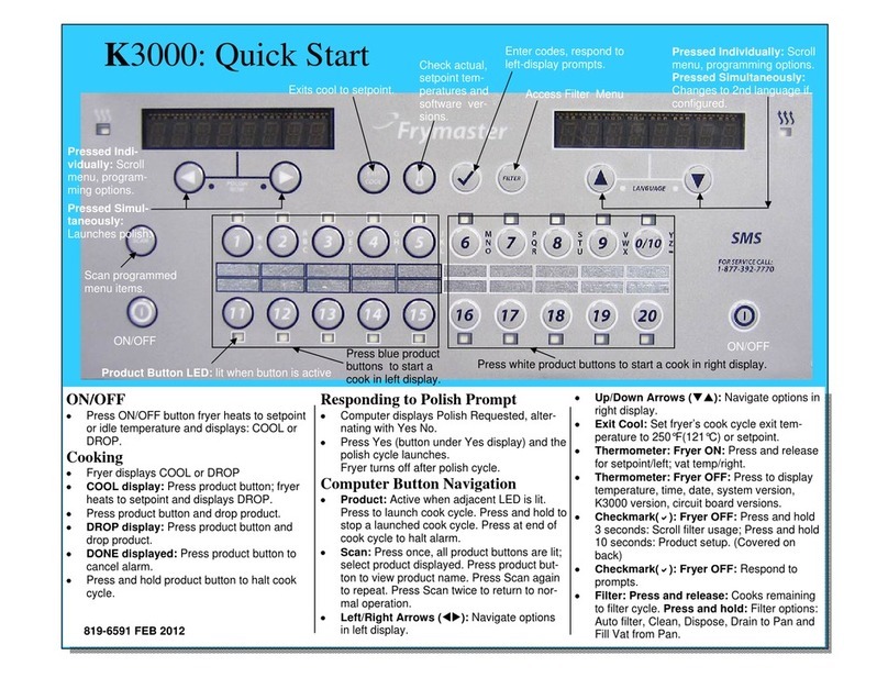
Frymaster
Frymaster FBR18LP Guide

Frymaster
Frymaster 1814 User manual

Frymaster
Frymaster K3000 User manual
Frymaster
Frymaster SDU 50 Guide
Frymaster
Frymaster FPPH355 User manual
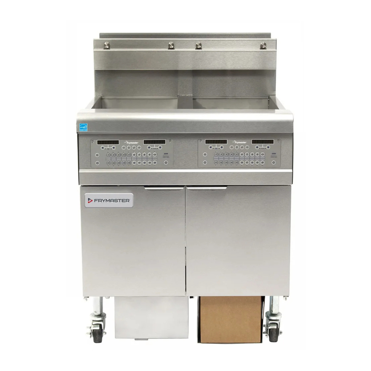
Frymaster
Frymaster LOV User manual

Frymaster
Frymaster FPGL Series User manual
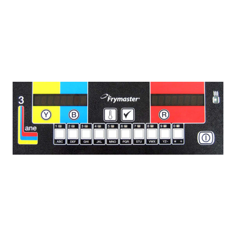
Frymaster
Frymaster LOV M3000 User manual

Frymaster
Frymaster UHC User manual
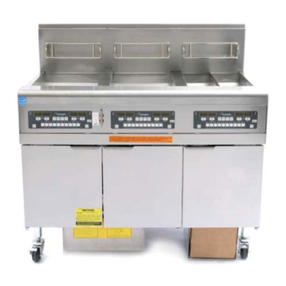
Frymaster
Frymaster YFG255 Guide
Popular Commercial Food Equipment manuals by other brands

Henny Penny
Henny Penny 6.15 Maintenance Instruction

Hussmann
Hussmann Multideck Meat 3750 installation manual

saro
saro EGN 1410 GN operating instructions

Hupfer
Hupfer SPA/K operating instructions

JAC
JAC GD Translation of original user instructions

Rational
Rational VarioCooking Center technical information