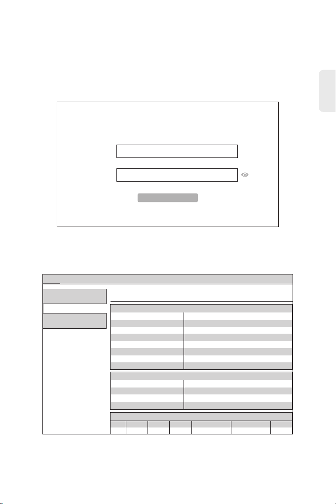
FS TA1910-4GVC-W User manual

PWR PON LOS FXS1 FXS2 LAN1 LAN2 LAN3 LAN4 2.4G 5G WPS CATV LOOP
GPON/EPON ONU
GPON/EPON ONU
GPON/EPON ONU
Quick Start Guide V1.0
Quick Start Anleitung
Guide de Démarrage Rapide
TA1910-4GVC-W

Introduction
Thank you for choosing TA1910-4GVC-W integrated broadband access device. This guide is designed
to familiarize you with the layout of the device and describes how to deploy the device in your network.
Accessories
TA1910-4GVC-W
PWR PON LOS FXS1 FXS2 LAN1 LAN2 LAN3 LAN4 2.4G 5G WPS CATV LOOP
1
EN
Stick ONU Module(Not included)Power Adapter x1

Front Panel Ports
Top Panel LEDs
Hardware Overview
PWR PON LOS FXS1 FXS2 LAN1 LAN2 LAN3 LAN4 2.4G 5G WPS CATV LOOP
PWR
FXS2
LOS
PON
CATV
WPS2.4GLAN1
LAN2
LAN3
LAN4
5G LOOPFXS1
PWR PON LOS FXS1 FXS2 LAN1 LAN2 LAN3 LAN4 2.4G 5G WPS CATV LOOP
4x LAN2x TELUSB PON RF
USB A USB management port for software, configuration backup and offline
software upgrade
Connect the telephone
Connect the computer or network television
Realize the access of GPON ONU
Radio-frequency signal transmission
TEL
LAN
PON
RF
Port Description
2
EN

3
EN
Power
LEDs
PON state
Optical signal
2.4GWifi state
5Gwifi state
Ethernet port
state
Voice port
state
WPS state
Loop state
Optical signal
receiving
Optical signal
receiving
Green
Green
Red
Green
Green
Green
Green
Green
Red
Red
Green
State
On: The system is powered on normally.
Off: The system is not powered on.
Off: The ONU is not activated.
On: The ONU has been activated.
Flicker: The ONU is being activated.
Off: The optical power is received normally.
Flicker: The received optical power is lower than the
threshold of the optical receiver.
Off: The system is not powered on or the Wifi port is not
connected to a network device.
On: The Wifi port is connected, but there is no data transmission.
Flicker: There is data transmission.
Off: The system is not powered on or the Wifi port is not
connected to a network device.
On: The Wifi port is connected, but there is no data transmission.
Flicker: There is data transmission.
Off: The system is not powered on or the Ethernet port does not
connect to the terminal.
On: The Ethernet port has been connected, but there is no data
transmission.
Flicker: There is data transmission through the port.
Off: The system is not powered on or the voice port is not
registered.
On: The voice port is registered successfully, but there is no data
transmission.
Flicker: There is data transmission on the voice port.
Off: The system is not powered on or the WPS is not enabled.
Flicker: The WPS connection is ongoing.
On: The WPS connection is successful.
Off: The system is not powered on or there is no loop on the port.
On: The lan port has a loop.
On: The input optical power is lower than -15dBm.
Flicker: The input optical power is higher than 3dBm.
Off: The device is not powered on.
On: The input optical power is between -15dBm and 3dBm.
Description

PWR PON LOS FXS1 FXS2 LAN1 LAN2 LAN3 LAN4 2.4G 5G WPS CATV LOOP
Installation Requirements
Installation
Desk Mounting
Make sure that the installation site is well-ventilated, the heat of electrical devices is
well-discharged and sufficient air circulation is provided for device cooling.
Use the rated power adapter equipped with the device.
Put the GPON on a smooth and safe desk directly.
To avoid thunder-strike, disconnect all power cords from the power supply and all cables in
thunder and rainy days.
Make sure the device is put on a horizontal and flat surface.
4
EN

PWR PON LOS FXS1 FXS2 LAN1 LAN2 LAN3 LAN4 2.4G 5G WPS CATV LOOP
USB
Connecting the USB port
Connecting the TEL Port
1. Insert the Universal Serial Bus(USB) flash disk to the USB port for software and configuration
backup and offline software upgrade.
Connecting the TEL port to a telephone with a cable.
5
EN
1 2 3
4 5 6
7 8
0
+
.
9
-
L2
L1
PWR PON LOS FXS1 FXS2 LAN1 LAN2 LAN3 LAN4 2.4G 5G WPS CATV LOOP

Connecting the LAN port to a computer or a network television with a network cable.
Connecting the LAN Port
6
EN
1. Insert a Stick ONU module into the PON port of the GPON.
2. Connect the Stick ONU module to an optical splitter with a single-mode SC optical fiber cable.
3. Then connect the splitter to an OLT with a fiber cable.
Connecting the PON port
PWR PON LOS FXS1 FXS2 LAN1 LAN2 LAN3 LAN4 2.4G 5G WPS CATV LOOP
P1 P3 P5 P7
CLI G1 G3 G1 G3 G5 G7
MGMT
OLT3610-08GP4S
ALM
G4 G8 T4 P4 P8
G1SYS G5 T1 P1 P5
P1
P2
T1 T2 T3 T4
PWR PON LOS FXS1 FXS2 LAN1 LAN2 LAN3 LAN4 2.4G 5G WPS CATV LOOP
PON
GPON

Configuring the GPON
Step 1: Click “Start-Control Panel-Network and Internet-Network and Sharing Center-Local Area
Connection”, select “Local Area Connection”, and click “Properties”
Connecting the RF port to a cable television with a network cable.
Connecting the RF Port
Computer Setting
7
EN
x
IPv4 Connectivity:
IPv6 Connectivity:
General
connection
Ethernet Status
Media State:
Duration:
Speed:
Internet
No Internet access
Enabled
00:00:56
100.0 Mbps
Activity
Details...
Bytes:
Sent Received
30,596 57,737
Properties
Close
Disable Diagnose
PWR PON LOS FXS1 FXS2 LAN1 LAN2 LAN3 LAN4 2.4G 5G WPS CATV LOOP

Step 2: Double click “Internet Protocol 4 (TCP/IPV4)” as shown in the following figure:
Step 3: On the page of Internet Protocol 4 (TCP/IPV4) Properties, select “ Obtain an IP address
automatically” and “Obtain DNS server address automatically”, and then click “OK”.
8
EN
x
Networking Sharing
OK Cancel
Ethernet Properties
Realtek PCle GBE Family Controller
Configure...
This connection uses the following items:
QoS Packet Scheduler
Microsoft Network Adapter Multiplexor Protocol
Microsoft LLDP Protocol Driver
Link-Layer Topology Discovery Mapper I/O Driver
Link-Layer Topology Discovery Responder
Internet Protocol Version 6 (TCP/IPv6)
Internet Protocol Version 4 (TCP/IPv4)
Transmission Control Protocol/Internet Protocol. The default
wide area network protocol that provides communication
across diverse interconnected networks.
Connect using:
PropertiesInstall... Uninstall
Description
x
General
You can get IP settings assigned automatically if your network supports
this capability. Otherwise, you need to ask your network administrator
for the appropriate IP settings.
. . .
OK Cancel
IP address:
Subnet mask:
Default gateway:
Use the following IP address:
Obtain an IP address automatically
Preferred DNS server:
Alternate DNS server:
Validate settings upon exit Advanced...
. . .
. . .
. . .
. . .
Obtain DNS server address automatically
Use the following DNS server addresses:
Alternate Configuration
Internet Protocol Version 4 (TCP/IPv4) Properties

Step 1: Open the web browser, for instance: Google Chrome or Microsoft Edge.
Step 2: Enter 192.168.123.1 in the address bar and click “Enter” to the web interface. Then enter the
UserName (user by default) and Password (123456 by default) respectively in the interface
UserLogin.
Step 3: After Login, click “Status” on top of the navigation. Click “Device Basic Info” on the left
navigation bar. Basic information of the device is shown in the following page.
Wizard Setting
9
EN
Login
Input username and password
Username:
Password:
*****
User
Status
Status
LAN WLAN Service Admin
Device Status
This page shows the current status and some basic settings of the device.
System
Device Name GP1705-4GV
IPv6
Device
Uptime 5 min
Firmware Version 10.0.33D.1034
CPU Usage 1%
17%
Memory Usage
Name Servers 8.8.8.8, 114.114.114.114
IPv4 Default Gateway
IPv6 Default Gateway
10.114.0.1
LAN Configuration
IP Address
Subnet Mask
192.168.123.1
255.255.255.0
DHCP Server Enabled
0055B16FF58AMAC Address
WAN Configuration
VLAN ID IP Address Gateway StatusInterface
nas0_0 100
Connection Type
INTERNET
Protocol
IPoE 10.114.0.53 10.114.0.1 up

Step 4: Click “WLAN” in “Network” to select whether to enable wireless. And you can also modify
the wireless name, authentication mode and password.
Step 5: Click “Apply Changes” to proceed to the next step.
If you want to use the wireless network, please make sure your PC is equipped with the wireless
adapter card, then do as following steps. Here takes Windows 7 System as an instance:
Step 1: Select “Network” and “Properties”
System Setting
10
EN
Status LAN WLAN Service Admin
wlan0 (2.4GHz)
Basic Settings
WLAN Basic Settings
This page is used to configure the parameters for WLAN clients which may connect to your Access Point. Here you may
change wireless encryption settings as well as wireless network parameters.
Disable WLAN Interface
2.4 GHZ(B+G+N)
Security
Advanced Settings
Access Control SSID: 2.4G-F58A
AP
Mode:
Channel Width: 20MHz
Control Sideband:
Channel Number: Auto
Radio Power (%):
Status
100%
MESH
Site Survey
WPS
wlanl (5GHz)
Disabled
Limit Associated Client
Number:
Associated Clients: Show Active WLAN Clients
Enable Universal Repeater Mode (Acting as AP and client simultaneouly)
Apply Changes
Upper
Multiple AP
Band:
network
Open
Pin to Start
Map network drive...
Disconnect network drive.…
Create shortcut
Delete
Properties

Step 2: Click “Wireless Network Connection”.
Step 3: Click the “Refresh” button, select the wireless network name of the terminal device, and
double-click the name.
11
EN
x
<< Net... Network and Sharing Cen...
<
Search Control Panel
Control Panel Home
Change adapter settings
Change advanced sharing
settings
View your basic network information and set up connections
View your active networks
HGU-6E78
Private network
Access type: Internet
HomeGroup: Ready to create
Set up a new connection or network
Change your networking settings
Set up a broadband, dial-up, or VPN connection; or set up a router or
access point.
Troubleshoot problems
Diagnose and repair network problems, or get troubleshooting
information.
See also
HomeGroup
Internet Options
Windows Firewall
Connections: Ethernet
Network and Sharing Center
HGU-Sanjid
Connect automatically
Connect

Step 4: Enter the password and click “OK”.
12
WiFi Has signal on the PC but it cannot connect to the Internet.
1. Check whether the WiFi name is the same with SSID of the wireless router;
2. Check the strength of the wireless signal. Adjust the location of the wireless router, if the wireless
signal is weak.
3. Refresh the network list and re-connect to the WiFi;
4. Consult the manufacturer of the notebook or wireless adapter card and re-connect according to
the relevant guidelines;
5. Restart the PC.
Troubleshooting
EN
Type the network security key
Security key: ········
Hide Characters
x
OK Cancel
Connect to a Network

WiFi Has No signal on the PC
1. Check whether the wireless adapter card is enabled;
2. Check whether the driver of the wireless adapter card is successfully installed. If not, please reinstall;
3. Check whether the WiFi function of the wireless router is enabled and access to SSID broadcast;
4. Check whether the WiFi service is enabled. Right-click “My computer” on the desk of home screen
(take Windows 7 as an example) and select “Management”. Then select “service and application
program”, and select “service” after the page is unfolded. Find “WLAN AutoConfig” and ensure it is
enabled;
5. Check whether there is wireless signal if keeping the PC closer to the wireless router.
6. Retry to connect other wireless adapter card if the above solutions are unsatisfactory. If not, reset
the wireless router.
Product Warranty
Warranty: The GPON ONU enjoys 1 year limited warranty against defect in materials or
workmanship. For more details about warranty, please check at:
https://www.fs.com/policies/warranty.html
Return: If you want to return item(s), information on how to return can be found at:
https://www.fs.com/policies/day_return_policy.html
1
13
EN
Online Resources
Download
Help Center
Contact Us
https://www.fs.com/products_support.html
https://www.fs.com/service/fs_support.html
https://www.fs.com/contact_us.html

Einführung
Vielen Dank, dass Sie sich für das integrierte Breitbandzugangsgerät TA1910-4GVC-W entschieden
haben. Diese Anleitung soll Sie mit dem Aufbau des Geräts vertraut machen und erklärt, wie Sie es
in Ihrem Netzwerk einsetzen.
Zubehör
TA1910-4GVC-W
ONU Stick Modul (nicht im Lieferumfang enthalten)Netzadapter x1
14
DE
PWR PON LOS FXS1 FXS2 LAN1 LAN2 LAN3 LAN4 2.4G 5G WPS CATV LOOP

PWR PON LOS FXS1 FXS2 LAN1 LAN2 LAN3 LAN4 2.4G 5G WPS CATV LOOP
PWR
FXS2
LOS
PON
CATV
WPS2.4GLAN1
LAN2
LAN3
LAN4
5G LOOPFXS1
PWR PON LOS FXS1 FXS2 LAN1 LAN2 LAN3 LAN4 2.4G 5G WPS CATV LOOP
4x LAN2x TELUSB PON RF
Ports an der Vorderseite
LEDs an der Oberseite
Hardware-Übersicht
USB Ein USB-Verwaltungsport für Software, Konfigurationsbackups und
Offline-Software-Upgrades
Verbindet das Telefon
Verbindet den Computer oder den Netzwerkfernseher
Ermöglicht den Zugang von GPON ONU
Übertragung von Hochfrequenzsignalen
TEL
LAN
PON
RF
Port Beschreibung
15
DE

Strom
LED
PON Zustand
Optisches
Signal
2,4G Wifi-
Zustand
5G Wifi-
Zustand
Ethernet-
Port-Zustand
Sprachport-
Zustand
WPS-
Zustand
Loop-
Zustand
Empfang von
optischen
Signalen
Empfang von
optischen
Signalen
Grün
Grün
Rot
Grün
Grün
Grün
Grün
Grün
Rot
Rot
Grün
Status
Ein: Das System ist normal eingeschaltet.
Aus: Das System ist nicht eingeschaltet.
Aus: Die ONU ist nicht aktiviert.
Ein: Die ONU ist aktiviert.
Blinken: Die ONU wird aktiviert.
Aus: Die optische Leistung wird normal empfangen.
Blinken: Die empfangene optische Leistung ist niedriger als der
Schwellenwert des optischen Empfängers.
Aus: Das System ist nicht eingeschaltet oder der Wifi-Port ist nicht
mit einem Netzwerkgerät verbunden.
An: Der Wifi-Port ist verbunden, aber es findet keine
Datenübertragung statt.
Blinken: Es findet eine Datenübertragung statt.
Aus: Das System ist nicht eingeschaltet oder der Wifi-Port ist nicht
mit einem Netzwerkgerät verbunden.
Ein: Der Wifi-Port ist verbunden, aber es findet keine
Datenübertragung statt.
Blinken: Es findet eine Datenübertragung statt.
Aus: Das System ist nicht eingeschaltet oder der Ethernet-Port ist
nicht mit dem Terminal verbunden.
An: Der Ethernet-Port ist angeschlossen, es findet jedoch keine
Datenübertragung statt.
Blinken: Es findet eine Datenübertragung über den Port statt.
Aus: Das System ist nicht eingeschaltet oder der Sprachanschluss
ist nicht registriert.
Ein: Der Sprachanschluss ist erfolgreich registriert, aber es findet
keine Datenübertragung statt.
Blinken: Es findet eine Datenübertragung über den
Sprachanschluss statt.
Aus: Das System ist nicht eingeschaltet oder die WPS-Funktion ist
nicht aktiviert.
Blinken: Die WPS-Verbindung ist im Betrieb.
An: Die WPS-Verbindung ist hergestellt.
Aus: Das System ist nicht eingeschaltet oder es gibt keine Schleife
auf dem Port.
An: Der Lan-Port hat eine Schleife.
An: Die optische Eingangsleistung ist niedriger als -15dBm.
Blinken: Die optische Eingangsleistung ist höher als 3dBm.
Aus: Das Gerät ist nicht eingeschaltet.
An: Die optische Eingangsleistung liegt zwischen -15dBm und
3dBm.
Beschreibung
16
DE

PWR PON LOS FXS1 FXS2 LAN1 LAN2 LAN3 LAN4 2.4G 5G WPS CATV LOOP
Installationsanforderungen
Installation
Montage auf dem Schreibtisch
Stellen Sie sicher, dass der Aufstellungsort gut belüftet ist, die Wärme der elektrischen Geräte gut
abgeleitet wird und eine ausreichende Luftzirkulation zur Kühlung des Geräts gewährleistet ist.
Verwenden Sie den mit dem Gerät gelieferten Netzadapter.
Stellen Sie den GPON direkt auf einen glatten und sicheren Tisch.
Ziehen Sie bei Gewitter und Regen alle Netzkabel aus der Steckdose, um einen Blitzschlag zu
vermeiden.
Achten Sie darauf, dass das Gerät auf einer horizontalen und ebenen Fläche aufgestellt wird.
17
DE

1 2 3
4 5 6
7 8
0
+
.
9
-
L2
L1
PWR PON LOS FXS1 FXS2 LAN1 LAN2 LAN3 LAN4 2.4G 5G WPS CATV LOOP
Anschließen des USB-Ports
Anschließen des TEL-Ports
1. Stecken Sie die Universal Serial Bus (USB)-Flash-Disk in den USB-Port ein, um die Software und
die Konfiguration zu sichern und die Software offline zu aktualisieren.
Anschließen des TEL-Anschlusses an ein Telefon mit einem Kabel.
18
DE
PWR PON LOS FXS1 FXS2 LAN1 LAN2 LAN3 LAN4 2.4G 5G WPS CATV LOOP
USB

Anschließen des LAN-Ports an einen Computer oder ein Netzwerkfernsehgerät mit einem
Netzwerkkabel.
Anschließen des LAN-Ports
1. Stecken Sie ein ONU-Stick-Modul in den PON-Port des GPONs.
2. Verbinden Sie das ONU-Stick-Modul mit einem optischen Splitter über ein Singlemode-SC-
Glasfaserkabel.
3. Verbinden Sie dann den Splitter über ein Glasfaserkabel mit einem OLT.
Anschließen des PON-Ports
19
DE
PWR PON LOS FXS1 FXS2 LAN1 LAN2 LAN3 LAN4 2.4G 5G WPS CATV LOOP
P1 P3 P5 P7
CLI G1 G3 G1 G3 G5 G7
MGMT
OLT3610-08GP4S
ALM
G4 G8 T4 P4 P8
G1SYS G5 T1 P1 P5
P1
P2
T1 T2 T3 T4
PWR PON LOS FXS1 FXS2 LAN1 LAN2 LAN3 LAN4 2.4G 5G WPS CATV LOOP
PON
GPON
Table of contents
Languages:
Other FS Network Router manuals
Popular Network Router manuals by other brands

KYLAND Technology
KYLAND Technology SICOM6028GPT Hardware installation manual

Technicolor
Technicolor DGA0122 quick start guide

Huawei
Huawei AR1200 Series Compliance and Safety Manual

Huawei
Huawei EG8147X6 troubleshooting manual

Billion
Billion BiPAC 5200W RC user manual

Maestro Wireless Solution
Maestro Wireless Solution E220 Series quick start guide

Alba Fiber Systems
Alba Fiber Systems AFS8202M Series Installation & operation instructions

Ruijie
Ruijie RG-RSR77 Series Quick installation guide

MDT Technologies
MDT Technologies SCN-IP100.03 Technical manual

HALNy
HALNy HL-4GXV-F Quick installation guide

Allied Telesis
Allied Telesis AT-8000GS/24 datasheet

Cisco
Cisco SOHO 91 Specifications