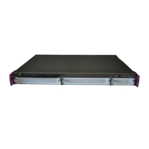
Teldat RXL15000 User manual

Teldat Edge Router RXL15000
Installation Manual
Copyright© Teldat-DM1055-I Version 1.0 05/2023 Teldat S.A.
Teldat S.A. Manual
Teldat Edge Router RXL15000 1

Legal Notice
Warranty
This publication is subject to change.
Teldat S.A. offers no warranty whatsoever for information contained in this manual.
Teldat S.A. is not liable for any direct, indirect, collateral, consequential or any other damage connected to the deliv-
ery, supply or use of this manual.
Manual Teldat S.A.
2Teldat Edge Router RXL15000

Table of Contents
I RelatedDocuments................................. 1
Chapter1 AboutthisGuide.................................. 2
1.1 Supporteddevices................................... 2
1.2 Who should read this manual? . . . . . . . . . . . . . . . . . . . . . . . . . . . . . . 2
1.3 When should this manual be read? . . . . . . . . . . . . . . . . . . . . . . . . . . . . 2
1.4 Whatisinthismanual?................................. 2
1.5 Whatisnotinthismanual? ............................... 2
1.6 How is the information organized? . . . . . . . . . . . . . . . . . . . . . . . . . . . . 2
1.7 Technicalsupport.................................... 2
Chapter2 RXL15000 ..................................... 3
2.1 Characteristics..................................... 3
2.1.1 Powersupply ..................................... 3
2.1.2 Hardwaremonitoring.................................. 3
Chapter 3 Components and Power Supply . . . . . . . . . . . . . . . . . . . . . . . . . . 4
3.1 Components...................................... 4
3.1.1 Frontpanel ...................................... 4
3.1.2 Rearpanel....................................... 6
3.2 Installation....................................... 7
3.2.1 Standalone ...................................... 7
3.2.2 Wallmounting..................................... 7
3.2.3 19''Rackinstallation .................................. 7
3.3 Powersource ..................................... 7
3.4 RSTbutton ...................................... 8
3.4.1 Rebootingthedevice.................................. 8
3.4.2 Defaultconfiguration.................................. 8
3.5 Connectingthedata................................... 8
3.5.1 8-port Ethernet switch connections . . . . . . . . . . . . . . . . . . . . . . . . . . . . 8
3.5.2 SFP/SFP+connections................................. 9
3.5.3 Connecting for configuration . . . . . . . . . . . . . . . . . . . . . . . . . . . . . . . 9
Chapter4 Compliance.................................... 11
4.1 Manufacturerinformation ............................... 11
4.2 Riskidentification................................... 11
Teldat S.A. Table of Contents
Teldat Edge Router RXL15000 i

4.3 Safetywarnings ................................... 13
4.4 WEEEinformation.................................. 13
4.5 REACH....................................... 13
4.6 EC declaration of conformity . . . . . . . . . . . . . . . . . . . . . . . . . . . . . . 13
4.7 Laserproduct .................................... 14
Appendix A Technical Information. . . . . . . . . . . . . . . . . . . . . . . . . . . . . . . 15
A.1 Troubleshooting................................... 15
A.2 Updatingthesoftware................................. 15
A.3 Connectingtothedevice ............................... 15
A.3.1 Connecting using the local console (Conf connector) . . . . . . . . . . . . . . . . . . . 15
A.4 Connectors ..................................... 16
A.4.1 EthRJ45connector.................................. 16
A.4.2 EthSFP/SFP+connector............................... 16
A.4.3 USB3.0connector.................................. 17
A.4.4 Configurationconnector................................ 17
A.5 Technicalspecifications................................ 17
A.5.1 Hardwarearchitecture................................. 17
A.5.2 EthRJ45interface.................................. 18
A.5.3 EthSFP/SFP+interface................................ 18
A.5.4 USB3.0interface................................... 18
A.5.5 Configurationinterface ................................ 18
A.5.6 Powersupply .................................... 18
A.5.7 Dimensionsandweight................................ 18
A.5.8 Environmental specifications . . . . . . . . . . . . . . . . . . . . . . . . . . . . . . 18
Table of Contents Teldat S.A.
ii Teldat Edge Router RXL15000

I Related Documents
Teldat Dm748-I Software Updating
Teldat S.A. Related Documents
Teldat Edge Router RXL15000 1

Chapter 1 About this Guide
This installation guide for the RXL15000 router contains information on how to correctly install this device in a work-
ing environment.
1.1 Supported devices
The information provided in this installation guide only applies to the RXL15000 router.
1.2 Who should read this manual?
This manual should be read by the support personnel who need to configure, maintain and monitor the device.
1.3 When should this manual be read?
Read this guide as soon as you are ready to familiarize yourself with the device and its components.
This manual will help you understand your new device in greater depth.
1.4 What is in this manual?
This installation guide contains the following information:
• A description of the features available in the RXL15000 router.
• Technical specifications.
• Power supply requirements.
• Elements that can be connected when the router is operating.
• A description of the device LEDs and connectors.
• Troubleshooting.
1.5 What is not in this manual?
This manual does not contain information relative to the device software or its configuration. For information on how
to configure this device, please see the relevant protocol manuals found on the Teldat website: http://www.teldat.com
1.6 How is the information organized?
Each chapter focuses on a specific part of the hardware and its components. All descriptive or technical specifica-
tions, and information on a component, can be found in the relevant chapter.
1.7 Technical support
Teldat S.A. offers technical support. Device software can be upgraded on a regular basis for maintenance purposes
and in case new features are developed.
Contact information:
Tel.: +34 918 076 565 - Fax: +34 918 076 566
1 About this Guide Teldat S.A.
2Teldat Edge Router RXL15000

Chapter 2 RXL15000
Fig. 1: RXL15000
2.1 Characteristics
2.1.1 Power supply
For further information on the different RXL15000 power supplies, please see Components and Power Supply on
page 4, section Power source on page 7.
2.1.2 Hardware monitoring
The LEDs on the front panel are used to monitor the hardware in the RXL15000 router. These LEDs provide visual
information on the state of the device and reference the condition of the hardware components, indicating whether
there is connectivity, data flow, etc.
For further information on the LED panel, please see Components on page 4.
Teldat S.A. 2 RXL15000
Teldat Edge Router RXL15000 3

Chapter 3 Components and Power Supply
The following chapter provides detailed information on the chassis of the RXL15000 router and its components. This
information includes:
• Components
• Information on installation
• Power supply
• RST button
• Data connection
3.1 Components
3.1.1 Front panel
The following figure shows the front panel. Here you will find the majority of the RXL15000 router connectors.
Fig. 2: Front Panel
The front panel components are as follows:
Front panel components
Item Description
A RST. Reset button.
For further information on how the reset button works, please see RST button on
page 8.
B LED panel.
For detailed information on the LEDs, refer to LEDs on page 5
C Conf.
Provides access to the RXL15000 local console for configuring and monitoring
purposes. For more information, refer to:
-Connecting for configuration on page 9
-Configuration connector on page 17
-Configuration interface on page 18
D USB 3.0 Ports.
The USB Ports do not provide data connections and are intended for maintenance
use only.
For more information on the USB connectors, refer to:
-USB 3.0 connector on page 17
-USB 3.0 interface on page 18
3 Components and Power Supply Teldat S.A.
4Teldat Edge Router RXL15000

E 8-port Gigabit Ethernet Switch.
For more information on the Gigabit Ehternet switch interface, refer to:
-8-port Ethernet switch connections on page 8
-Eth RJ45 connector on page 16
-Eth RJ45 interface on page 18
F 4-port 1/10 Gigabit Ethernet SFP/SFP+.
For more information on the Gigabit Ehternet switch interface, refer to:
-SFP/SFP+ connections on page 9
-Eth SFP/SFP+ connector on page 16
-Eth SFP/SFP+ interface on page 18
3.1.1.1 LEDs
The LED panel provides information on the status of the components (whether they are active or not) and on the net-
work activity.
Fig. 3: Front panel LEDs
LEDs
LED Definition Status Indication
A Power Off -> Error.
On -> Power Supply OK.
B System Off -> System error.
On -> System initialized and operating.
C Cloud Information Off -> No cloud configuration.
On -> Connected to the cloud. Blinking: traffic exchange with the
cloud controller.
D Reserved Future purposes.
In addition to the LEDs described in the above table, the front panel also has LEDs linked to the Switch Ethernet and
SFP/SFP+ interfaces.
Fig. 4: Ethernet interface LEDs
The table below provides information on the LEDs associated with the Switch Ethernet interface:
Switch Ethernet interface LED indicators
Teldat S.A. 3 Components and Power Supply
Teldat Edge Router RXL15000 5

LED Description State
Left Ethernet link connection and activity Off -> Link has not been detected.
Yellow -> Link detected. Right LED indicates
speed status.
Blinking: connection data activity.
Right Ethernet link speed Off -> No link or 10M link.
Green -> 100M link.
Yellow -> 1000M link.
Fig. 5: SFP/SFP+ interface LEDs
The table below provides information on the LEDs associated with the SFP/SFP+ interfaces:
SFP/SFP+ LED indicators
LED Description State
Green Ethernet link connection Off -> Link has not been detected.
On -> Link detected. Blinking: connection
data activity.
3.1.2 Rear panel
The following figure shows the rear panel.
Fig. 6: Rear panel
The following table provides information and a description of each component:
Rear panel components
Item Description
A Ventilation slots.
B Power sockets.
Refer to Power source on page 7 for more information on Power Connection and
Power supply on page 18 for power specifications applicable to theRXL15000
device.
3 Components and Power Supply Teldat S.A.
6Teldat Edge Router RXL15000

3.2 Installation
In the following sections you can find guidelines for the RXL15000 installation.
Warning
Only trained and qualified personnel should be allowed to install, replace, or service this equipment.
Warning
This unit is intended for installation in restricted access areas.
A restricted access area can be accessed by skilled, instructed, or qualified personnel.
3.2.1 Standalone
RXL15000 devices can be placed as standalone devices on a flat, stable surface. The adhesive rubber feet must be
stuck to the underside panel to prevent the router from sliding.
Make sure there is enough space around the router (for ventilation purposes) and check that the power cord and
data cables can easily reach it.
Workplace conditions. Main characteristics
• Avoid humid and/or dusty locations.
• Direct exposure to sunlight and other heat sources should be avoided. The device should not be placed amongst
papers, magazines or other elements that could hinder natural air circulation.
• The device should not be placed close to strong electromagnetic fields (such as speakers, engines, etc.).
• Knocks and/or strong vibrations should be avoided during transport, operation and storage.
3.2.2 Wall mounting
RXL15000 devices cannot be mounted on the wall.
3.2.3 19'' Rack installation
RXL15000 devices can be installed in a 19” rack.
3.3 Power source
The RXL15000 router is powered through two internal AC/DC sources. The RXL15000 has two power inputs and
two power supplies that operate simultaneously. It can operate one, the other, or both at once. If the RXL15000 is
powered by the two power supplies and one of them fails, the other acts as a backup.
There is no on/off switch or fuse. The power supply information is printed on a label found at the rear of the device.
Warning
Safety regulations require that the location where the equipment is installed must incorporate a discon-
nection device (thermal circuit breaker), that is duly approved and whose nominal current is equal to or
less than 10 A.
To avoid electric shocks, residual current circulation, and other unwanted effects that also affect communications, the
following is recommended:
Teldat S.A. 3 Components and Power Supply
Teldat Edge Router RXL15000 7

Warning
All interconnected communication devices should be plugged into THE SAME GROUNDED POWER
OUTLET, which should at the same time be of good quality (lower than 10 ohms).
We recommend connecting all data devices to the same power source regardless of whether the work-
place has an uninterrupted power supply system (UPS), a regulated supply or is independent of other
power supplies (such as lighting, etc.). This will help prevent malfunctions and premature aging of the
drivers and other components.
There is no on/off switch or fuse. The electrical rating is printed on a label found on the rear of the device.
3.4 RST button
The different RST button features are described below.
Fig. 7: RST button
3.4.1 Rebooting the device
Once the device is operating normally, pressing the RST button will force a restart.
3.4.2 Default configuration
The RST button allows you to boot the device with its default configuration through the following steps:
• With the device switched off, keep the RST button pressed until the device switches on.
• The A LED (green) will begin to blink. This blinking will continue for 10 seconds.
• For the device to boot with the default configuration, release the Reset button while the A LED is blinking (i.e., be-
fore the 10-second period expires).
Once the default configuration is running, the router's default configuration establishes the following access IP and
mask address:
• IP address: 192.168.0.1
• IP mask: 255.255.255.0
Note
Some devices leave the factory with customized settings. This personalization means your router's de-
fault configuration (and that of the embedded access point, where applicable) may be different from the
one shown above.
3.5 Connecting the data
The RXL15000 router has the following data connections.
3.5.1 8-port Ethernet switch connections
The RXL15000 router incorporates an 8-port 10/100/1000 Base-T Switch with automatic MDI/MDIX to connect to a
local area network (LAN).
3 Components and Power Supply Teldat S.A.
8Teldat Edge Router RXL15000

Please pay careful attention to the labeling to avoid mixing up this switch with other port types:
Fig. 8: LAN switch PORTS
Note
During booting and in BIOS mode, only the LAN 1 connector is available.
3.5.2 SFP/SFP+ connections
The RXL15000 has 4 Gigabit Ethernet interfaces for WAN connection. These interfaces are totally independent from
the Switch and are handled as just one more interface.
Fig. 9: WAN connectors
Note
During booting and in BIOS mode, the SFP/SFP+ connectors do not work.
Note
Do not install or remove the SFP/SFP+ transceiver module with fiber-optic cables still attached to it. Do-
ing so may damage cables, cable connectors, or the optical interfaces and may interfere with the trans-
ceiver module latching properly into its socket connector. Disconnect all cables before removing or in-
stalling an SFP/SFP+ transceiver module.
Note
The SFP/SFP+ transceiver modules are static sensitive devices. Always use an ESD wrist strap or sim-
ilar individual grounding device when handling SFP/SFP+ transceiver modules or coming in contact
with modules.
Note
Be careful when removing the SFP/SFP+ transceiver module from the router. The transceiver module
temperature might go over 70ºC (160°F) and be too hot to touch with bare hands.
3.5.3 Connecting for configuration
The RXL15000 has a RJ45 female connector on the front panel (labeled "Conf") that provides access to the device's
local console.
Teldat S.A. 3 Components and Power Supply
Teldat Edge Router RXL15000 9

Chapter 4 Compliance
4.1 Manufacturer information
Brand Teldat
Manufacturer Teldat S.A.
Country Spain
Postal Address Isaac Newton, 10
Parque Tecnológico de Madrid, 28760
Tres Cantos, Madrid, Spain
International Phone +34 91 807 65 65
4.2 Risk identification
WARNING: Signal word used to designate a potentially dangerous situation that
may cause severe injuries or death if not avoided.
Teldat S.A. 4 Compliance
Teldat Edge Router RXL15000 11

4.3 Safety warnings
!
" # $ # % &
# %
'% !
! % !
( & ! )
! * !
%
+ !,
-.
( % &
/& +%0, 0
% % -.
%% 1" 2" 34)56"6
78"4 )(" % + -. ,
' %
! +)7, %
+ %% ,
%%
# )5 2'2
2 6" '"44 + -. ,
& # & ' + ',
& + ,
& 9 #
* #
( 6 / : -
;7 ! - %
'":<"5 =.>?@-A?..B
4& 5 / & 7
-
4 Compliance Teldat S.A.
12 Teldat Edge Router RXL15000

( & ;7 ! * 9
- '":<"5 =.>?@-A?..B
4.4 WEEE information
The crossed-out wheelie bin symbol indicates that the device must be disposed of
separately from normal domestic waste in an appropriate waste disposal facility
when it comes to the end of its useful life.
El símbolo del contenedor con la cruz, que se encuentra en el aparato, significa
que cuando el equipo haya llegado al final de su vida útil, deberá ser llevado a los
centros de recogida previstos, y que su tratamiento debe estar separado del de
los residuos urbanos.
4.5 REACH
This product is in compliance with the European REACH Regulation (EC) No 1907/2006. The Candidate List of sub-
stances of very high concern for Authorization is published by ECHA and periodically updated. Teldat S.A. accounts
for substances found in a concentration over 0.1% in weight. A declaration is provided to customers upon request.
4.6 EC declaration of conformity
English (EN) Hereby, Teldat S.A. declares that the radio equipment type RXL15000 is in com-
pliance with:
Directive 2014/30/EU (EMC)
Directive 2014/35/EU (LVD)
Directive 2011/65/EU (RoHS)
of the European Parliament and of the Council.
Spanish (ES) Español Por la presente, Teldat S.A. declara que el tipo de equipo radioeléctrico
RXL15000 es conforme con:
Directiva 2014/30/UE (EMC)
Directiva 2014/35/UE (LVD)
Directiva 2011/65/UE (RoHS)
del Parlamento Europeo y del Consejo.
The full text of the EU declaration of conformity and additional product documentation is available at the following In-
ternet address: http://www.teldat.com
This equipment is in conformity with the CE procedures and marking.
Teldat S.A. 4 Compliance
Teldat Edge Router RXL15000 13

4.7 Laser product
Use only trained and qualified personnel to install or replace this device
Choose SFP/SFP+ transceivers that meet the following regulations
• Class 1
• IEC/EN60825-1:2007 2nd Edition or later, European standard
• FCC 21 CFR Chapter 1, Subchapter J (in accordance with FDA and CDRH re-
quirements)
• Application of CE marking in accordance with the 2014/30/EU EMC Directive
and the 2014/35/EU Low Voltage Directives
• UL and/or CSA registered component for North America
• 47 CFR Part 15, Class A
4 Compliance Teldat S.A.
14 Teldat Edge Router RXL15000

Appendix A Technical Information
A.1 Troubleshooting
The following table can help you solve problems when installing the device. If you cannot solve the problem, contact
your dealer for more information.
Symptom Solution
None of the LEDs light up on
the router.
Check the power supply to the router (power source, ON/OFF switch, main power
outlet).
You have forgotten the router's
access password.
Ignore the configuration through the RST button (as explained in the relevant sec-
tion).
The LAN connector LED
doesn't light up.
Check the Ethernet cable and the connection to the network.
The SFP/SFP+ LED doesn't
light up in green.
Check the Ethernet cable and the connection to the network.
A.2 Updating the software
The RXL15000 router can be updated to new versions. Please contact your dealer for information on new releases.
A Teldat router can be updated in several ways. For further information, please see manual: “Teldat- Dm 748-I Soft-
ware Updating”.
The software required to update Teldat routers is supplied in a format known as distribution. This consists of a
single file containing all the files needed to update your device, as well as in-depth information on the contents of the
files.
A.3 Connecting to the device
A.3.1 Connecting using the local console (Conf connector)
The RXL15000 router has a RJ45 female connector on the front panel, known as "Conf", that provides access to the
device's local console.
Fig. 13: Conf Connector
To configure this, you must connect the "Conf" port to an asynchronous terminal (or to a PC with terminal emulation).
Note
The configuration for the terminal must be:
- Speed: 115200 bps.
- Eight data bits.
- One stop bit.
Teldat S.A. Technical Information
Teldat Edge Router RXL15000 15

- No parity bit.
- No type of flow control.
Connection to the configuration port can be done through the DB9 to RJ45 connector cable, supplied together with
the device.
A.4 Connectors
A.4.1 Eth RJ45 connector
RJ45 LAN RJ45 PIN FE Signals GE Signals
1
2
3
4
5
6
7
8
BI-DA+
BI-DA-
BI-DB+
--
--
BI-DB-
--
--
BI-DA+
BI-DA-
BI-DB+
BI-DC+
BI-DC-
BI-DB-
BI-DD+
BI-DD-
A.4.2 Eth SFP/SFP+ connector
SFP/SFP+
Standard SFP/SFP+ connector
Technical Information Teldat S.A.
16 Teldat Edge Router RXL15000
Table of contents
Other Teldat Network Router manuals
Teldat
Teldat C User manual

Teldat
Teldat G1N User manual

Teldat
Teldat H2 RAIL User manual

Teldat
Teldat RS1800 Series User manual

Teldat
Teldat iM8-Cx User manual

Teldat
Teldat Connect-FW User manual

Teldat
Teldat IMBER SMART User manual
Teldat
Teldat Regesta PLC User manual

Teldat
Teldat ATLAS 160 User manual
Teldat
Teldat RXL14000 User manual

Teldat
Teldat ATLAS 60 NW User manual

Teldat
Teldat M1 User manual

Teldat
Teldat ATLAS X60 User manual

Teldat
Teldat SDE User manual

Teldat
Teldat TLDPV00A1 User manual
Teldat
Teldat Teldat-3Ge User manual

Teldat
Teldat Connect-104 User manual

Teldat
Teldat 3ge User manual

Teldat
Teldat Regesta Smart PRO User manual

Teldat
Teldat K Seres User manual