9PIN PLUG CONNECTION
(1.6m of cable supplied as standard)
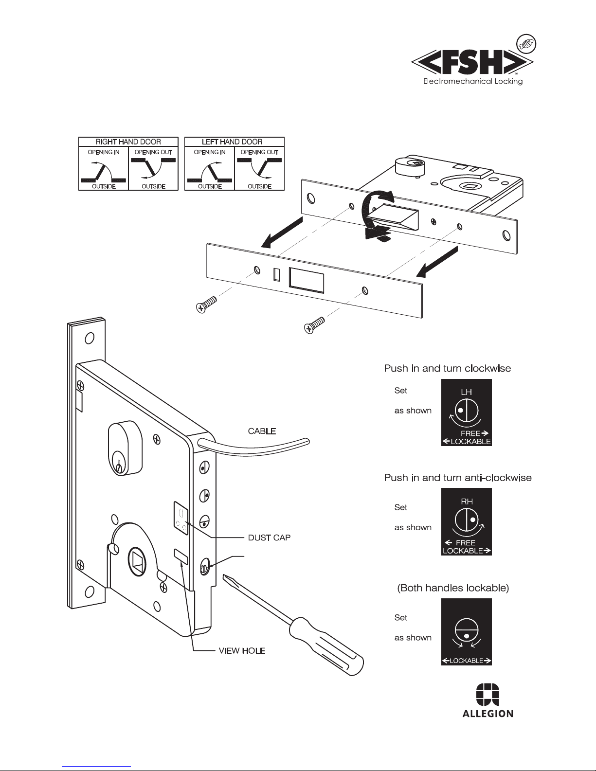
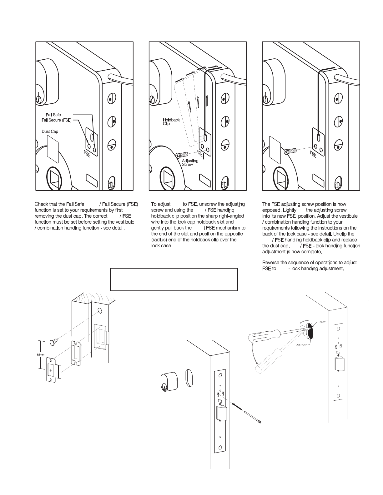
LOCK INSTALLATION
(swapping LED wires)
SWAPPING WIRES
Gently lift plastic tag
holding terminal & slide
wire terminal from plug.
To insert wire terminal,
slide back into plug.
This product is the subject of any one or more of the following patents,
NZ299577, AU717917, NZ529951, NZ535262, NZ534706, NZ534938,
NZ537284, NZ534626.
N
*
*Hub monitoring is exit side only
FSH Australia Pty Ltd
Phone 1300 374 374
Website www.fshlocking.com.au
NOTES: Swaping LED wires
over for Fail Secure (FSE) for
both LH/RH sides of lock.
LED cables are supplied as
standard to suit Fail Safe (FSA)
for both LH/RH sides of the
lock. On the occasion where
Fail Secure is selected the red
and green wires on the LED
cable will have to be swapped
over to suit LH/RH sides of
the lock.
FEL990 Series Monitoring Functions
Door Position Monitoring by Reed Switch
Lock Status Monitoring by a combination of 3 locking perimeters
• Locking Bar (Hub/Handle/s locked)
• Deadlatching Bolt (suppressed)
• Latchbolt (out)
Dual Key Override Monitoring (KOM)
Request to Exit (REX) via Hub/Handle(s)
LED Indication
ON OFF
FSH is an Allegion™ Company
Electrical Specications
Solenoid Activation
12-24V DC 350mA momentary, 100mA max operating
Including LED if applicable
Lock Secure Status/Key Override Monitor
Microswitch max. rating 500mA @30V DC
Door Status Monitor
Magnetic Reed Switch 100mA operating
Plug arrangement
9 pin plug with 1.6m cable
Request to Exit (REX) Switches
Microswitches max. rating 1A @125VAC
1
Solenoid Off
Solenoid On
Solenoid
NC
NO
Right Hand Operation (RH)
DIP 3
DIP 4
Reed Switch
NC
NO
Left Hand Operation (LH)
DIP 6
DIP 5
Dead Latching Bolt
NC
NO
Key Override
DIP2
DIP 1
Regulator
LED Drive
2
Black
Red
0 VDC
Solenoid
GreenLED (+) for Solenoid Off
Yellow Reed Switch
Grey Signals
Unused
Blue Hub Monitor (Handle)
Violet Key Overirde Monitor
Orange Latch Bolt, Dead Latching
Red LED
Lock Status :
Green LED
FEL990(M) Wire Connection Diagram
12-24VDC
Common
12-24VDC
(RH/LH, NO/NC)
Bolt & Lock/Unlock
(Both Sides)
Door Open at Rest
Unlocked (Fail Safe)
Door Locked
Fail Safe (FS)
Door Unlocked
Fail Safe (FS)
Swap LED Leads
for Fail Secure
(Secure Status)
(Door Closed Status)
9 Pin
Plug
NC
NO
Latch Bolt Monitor
Brown
Monitored version (M)
5
4
3
6
7
8
9
Locking Bar, (Handle(s) Locked)
POWER
9PIN PLUG CONNECTION
(1.6m of cable supplied as standard)
NOTE: Swaping LED wires over for Fail Secure (FSE) for
both LH/RH sides of lock.
LED cables are supplied as standard to suit Fail
Safe (FS) for both LH/RH sides of the lock. On
the occasion where Fail Secure is selected the
red and green wires on the LED cable will have
to be swapped over to suit LH/RH sides of the
lock.
LOCK INSTALLATION
(swapping LED wires)
SWAPPING WIRES
Gently lift plastic tag
holding terminal & slide
wire terminal from plug.
To insert wire terminal,
slide back into plug.
2
1
3
4
6
7
8
9
REGI COM Black
Red
SOLENOID
Common
Solenoid
Power for
LED Drive
12V –24V
NC
NO Door Closed &
Latched Status
Yellow
C
Lath
NC
Reed Switch
NO
NC
NO
Hub Monitor
(Common)
6
5
3
4
NC
NO 1
2
Hub Monitor
Grey
Blue
(RH/LH, NO/NC)
Violet
Orange
9 Pin
Plug
Key Override
Monitor
Key Override
(Common)
# Lock Status
RH Open Door at Rest
C
C
C
(L)
(R)
Unlocked (Fail Safe)
5
LED_CK Green
990 MFE Pin Allocation Diagram
Solenoid On
Solenoid Off
GREEN LED
(Door Open,
RED LED
Door Unsecure)
(Door locked Confirmed,
Door Secure)
Swap LED Leads
for Fail Secure
Brown
Door Closed &
Latched Status
(Common)
ELECTRIC SPECIFICATIONS
Hub Snib Activation (Solenoid Activiation)
12 V DC to 24V DC 350mA momentary, 100mA max. operating
Solenoid/Deadlatch/Key Override Monitor
Miniature lever microswitch max rating 500mA @ 30V DC
Door Status Monitor
Miniature magnetic reed switch 100mA operating
Plug Arrangements
990MFEi, 9 pin plug supplied with 1.6m cable
LED Current
LED current included as above
*
This product is the subject of any one or more of the following patents,
NZ299577, AU717917, NZ529951, NZ535262, NZ534706, NZ534938,
NZ537284, NZ534626.
Rex Switches
Sub-miniature D2 microswitch max. rating 1A@125V AC
Circuit sho ws right hand ope n door at rest .
N
*
*Hub monitoring is exit side only
Allegion (New Zealand) Limited
Phone 0800 477 869
Website www.allegion.co.nz
PIN Colour Function
1 Black O VDC
2 RedSolenoid black
3 Light Blue Solenoid, lath and deadbolt lock/unlock
4 Blue Hub monitor (handle) (RH/LH, NO/NC)
5 Grey Solenoid, lath and deadbolt common
6 Violet Key override monitor (both sides)
7 Brown Hub common
8 Pink Reed common
9 Orange Key override monitor
10 Yellow Reed switch (door closed status)
11 Green LED (+) for solenoid o 12-24VDC
12 White Lock/unlock (secure status) centre tap
1
Solenoid Off
Solenoid On
Solenoid
NC
NO
Right Hand Operation (RH)
DIP 3
DIP 4
Reed Switch
NC
NO
Left Hand Operation (LH)
DIP 6
DIP 5
Dead Latching Bolt
NC
NO
Key Override
DIP2
DIP 1
Regulator
LED Drive
2
Black
Red
0 VDC
Solenoid
Green
LED (+) for Solenoid Off
Yellow Reed Switch
Grey Solenoid, Latch & Deadbolt
Hub Common
Blue Hub Monitor (Handle)
Violet Key Overirde Monitor
Light Blue
Lock/Unlock (Secure Status)
Red LED
Lock Status :
Green LED
FEL990M (12 Pin) Wire Connection Diagram
12-24VDC
Common
12-24VDC
(RH/LH, NO/NC)
Lock/Unlock (Secure Status)
(Both Sides)
Door Open at Rest
Unlocked (Fail Safe)
Door Locked
Fail Safe (FS)
Door Unlocked
Fail Safe (FS)
Swap LED Leads
for Fail Secure
(Door Closed Status)
12 Pin
Plug
NC
NO
Latch Bolt Monitor
www.fshlocking.com.au
Brown
11
10
5
7
4
6
3
Locking Bar, (Handle(s) Locked)
Pink
8
Reed Common
Orange
9
White
12
Key Overirde Monitor
Solenoid, Latch & Deadbolt
Centre tap
9PIN PLUG CONNECTION
(1.6m of cable supplied as standard)
NOTE: Swaping LED wires over for Fail Secure (FSE) for
both LH/RH sides of lock.
LED cables are supplied as standard to suit Fail
Safe (FS) for both LH/RH sides of the lock. On
the occasion where Fail Secure is selected the
red and green wires on the LED cable will have
to be swapped over to suit LH/RH sides of the
lock.
LOCK INSTALLATION
(swapping LED wires)
SWAPPING WIRES
Gently lift plastic tag
holding terminal & slide
wire terminal from plug.
To insert wire terminal,
slide back into plug.
2
1
3
4
6
7
8
9
REGI COM Black
Red
SOLENOID
Common
Solenoid
Power for
LED Drive
12V –24V
NC
NO Door Closed &
Latched Status
Yellow
C
Lath
NC
Reed Switch
NO
NC
NO
Hub Monitor
(Common)
6
5
3
4
NC
NO 1
2
Hub Monitor
Grey
Blue
(RH/LH, NO/NC)
Violet
Orange
9 Pin
Plug
Key Override
Monitor
Key Override
(Common)
# Lock Status
RH Open Door at Rest
C
C
C
(L)
(R)
Unlocked (Fail Safe)
5
LED_CK Green
990 MFE Pin Allocation Diagram
Solenoid On
Solenoid Off
GREEN LED
(Door Open,
RED LED
Door Unsecure)
(Door locked Confirmed,
Door Secure)
Swap LED Leads
for Fail Secure
Brown
Door Closed &
Latched Status
(Common)
ELECTRIC SPECIFICATIONS
Hub Snib Activation (Solenoid Activiation)
12 V DC to 24V DC 350mA momentary, 100mA max. operating
Solenoid/Deadlatch/Key Override Monitor
Miniature lever microswitch max rating 500mA @ 30V DC
Door Status Monitor
Miniature magnetic reed switch 100mA operating
Plug Arrangements
990MFEi, 9 pin plug supplied with 1.6m cable
LED Current
LED current included as above
* Circuit shows right hand open door at rest.
This product is the subject of any one or more of the following patents,
NZ299577, AU717917, NZ529951, NZ535262, NZ534706, NZ534938,
NZ537284, NZ534626.
Rex Switches
Sub-miniature D2 microswitch max. rating 1A@125V AC
N
*
*Hub monitoring is exit side only
9PIN PLUG CONNECTION
(1.6m of cable supplied as standard)
NOTE: Swaping LED wires over for Fail Secure (FSE) for
both LH/RH sides of lock.
LED cables are supplied as standard to suit Fail
Safe (FS) for both LH/RH sides of the lock. On
the occasion where Fail Secure is selected the
red and green wires on the LED cable will have
to be swapped over to suit LH/RH sides of the
lock.
LOCK INSTALLATION
(swapping LED wires)
SWAPPING WIRES
Gently lift plastic tag
holding terminal & slide
wire terminal from plug.
To insert wire terminal,
slide back into plug.
2
1
3
4
6
7
8
9
REGI COM Black
Red
SOLENOID
Common
Solenoid
Power for
LED Drive
12V –24V
NC
NO Door Closed &
Latched Status
Yellow
C
Lath
NC
Reed Switch
NO
NC
NO
Hub Monitor
(Common)
6
5
3
4
NC
NO 1
2
Hub Monitor
Grey
Blue
(RH/LH, NO/NC)
Violet
Orange
9 Pin
Plug
Key Override
Monitor
Key Override
(Common)
# Lock Status
RH Open Door at Rest
C
C
C
(L)
(R)
Unlocked (Fail Safe)
5
LED_CK Green
990 MFE Pin Allocation Diagram
Solenoid On
Solenoid Off
GREEN LED
(Door Open,
RED LED
Door Unsecure)
(Door locked Confirmed,
Door Secure)
Swap LED Leads
for Fail Secure
Brown
Door Closed &
Latched Status
(Common)
ELECTRIC SPECIFICATIONS
Hub Snib Activation (Solenoid Activiation)
12 V DC to 24V DC 350mA momentary, 100mA max. operating
Solenoid/Deadlatch/Key Override Monitor
Miniature lever microswitch max rating 500mA @ 30V DC
Door Status Monitor
Miniature magnetic reed switch 100mA operating
Plug Arrangements
990MFEi, 9 pin plug supplied with 1.6m cable
LED Current
LED current included as above
*
This product is the subject of any one or more of the following patents,
NZ299577, AU717917, NZ529951, NZ535262, NZ534706, NZ534938,
NZ537284, NZ534626.
Rex Switches
Sub-miniature D2 microswitch max. rating 1A@125V AC
Circuit sho ws right hand ope n door at rest .
N
*
*Hub monitoring is exit side only
12
(3m of cable supplied as standard)
12 pin plug with 3m cable
VERSION ac.mob 09.16