FSK Rhino 232 User manual


CONTENTS
Getting Started ..................................................................................................................................... 4
Overview ...................................................................................................................................................................................................
Installation ..............................................................................................................................................................................................
Programming ........................................................................................................................................................................................
Rhino 232 Panel Overview ............................................................................................................. 5
Installation ...............................................................................................................................................
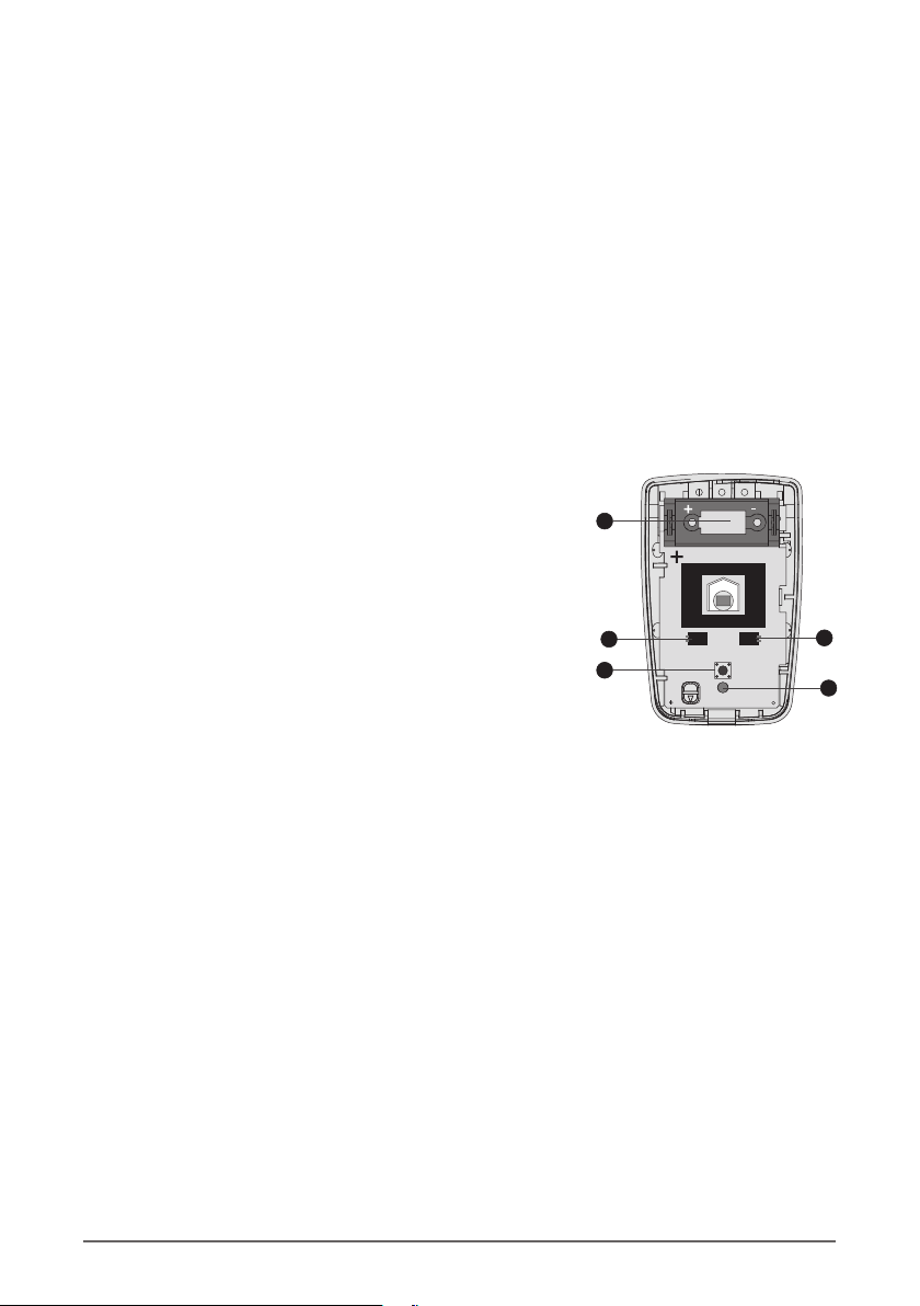
Mounting of the alarm panel .......................................................................................................................................................
Wiring the alarm panel ....................................................................................................................................................................
Power supply ..........................................................................................................................................................................................
Piezo Buzzers .........................................................................................................................................................................................
Sound bomb ..........................................................................................................................................................................................
Strobe lamp ............................................................................................................................................................................................
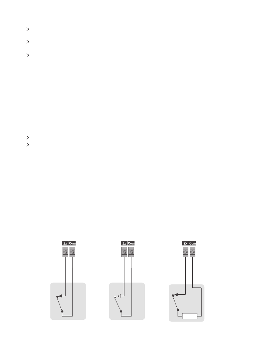
Wired zones ............................................................................................................................................................................................
Wiring .........................................................................................................................................................................................................
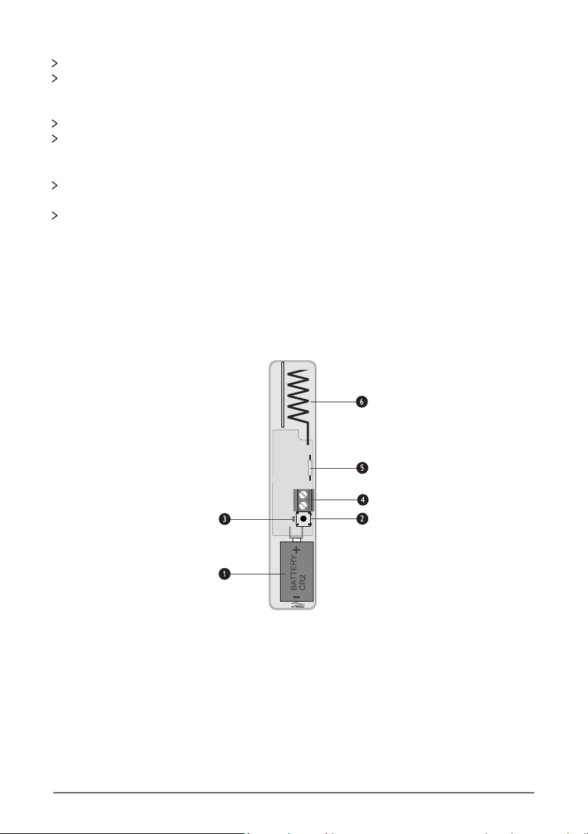
Wireless zones .......................................................................................................................................................................................
Programming .........................................................................................................................................
Entering the programming mode ............................................................................................................................................
Navigating the programming menus .....................................................................................................................................
Setting up zones ..................................................................................................................................................................................
Programming wireless zones ......................................................................................................................................................
Users ............................................................................................................................................................................................................
Area Options ..........................................................................................................................................................................................
Hardware options ...............................................................................................................................................................................
Keypad Options ...................................................................................................................................................................................
Outputs .....................................................................................................................................................................................................
Communications ................................................................................................................................................................................
Upload/Download (UDL) ................................................................................................................
Using the UDL ......................................................................................................................................................................................
Appendix A .............................................................................................................................................
Text Entry Mode ..................................................................................................................................................................................
Hex Entry Mode ...................................................................................................................................................................................
Warranty Information .......................................................................................................................
4
4
4
6
6
6
7
7
7
7
7
7
8
12
12
12
13
14
15
17
18
20
21
22
Zone Commissioning Process ..................................................................................................... 24
29
29
32
32
32
33

The Rhino 232 panel is a wireless alarm panel
The Rhino 232 panel is equipped with an onboard GSM modem which sends alarms to the
control room
The Rhino 232 panel works with the MiRhino mobile application which allows the user to
remotely control and monitor his or her alarm system
The Rhino 232 panel has been designed with ease-of-use, ease of installation and ease of
programming in mind
GETTING STARTED
1. Overview
2. Installation
Connect battery to the panel
Mount the panel in a location that has good GSM signal reception and that’s convenient
for the user
Wire the power supply to the alarm panel
Mount the sensors
Program the alarm panel
Perform the commissioning process
3. Programming
The keypad
The UDL (up/download) software supplied on the FSK DVD. The UDL programming can be
done locally via a USB connection or remotely via the FSK Gateway
The Rhino 232 alarm panel can be programmed via the following means:
4 Rhino 232 Installation Manual |

P O W E R STAT US TROUBLE
23
4 5 6
7 8 9
CLEAR 0ENTER CHIME
BYPASS
STAY
ARM
i
1P
The Rhino 232 panel Wireless Devices
Bi-Directional
Raptor Remote Gate Module
Indoor PIR Door Contact Third Party
PIR Interface
Optional
Power Supply
USB Port for
Programming
PC for Local
Upload/Download
OR
Remote Upload/Download
via the internet
Smart Phone Apps
RHINO 232 PANEL OVERVIEW
12V Strobe
(< 50mA)
12V Sound
Bomb
(< 200mA)
Piezo buzzers
Back view of panel
Rhino 232 Installation Manual 5 |

-+
Power Supply
Optional
12V Sound
Bomb
Optional
12V Strobe
5V FROM
POWER
SUPPLY
ZONE 2
ZONE 1
AUX
12V
5V
GND
SRN -+
STRB
Z1
Z2
COM
(≤ 200mA)
(≤ 50mA)
INSTALLATION
The alarm panel should be mounted in a location that has good GSM signal strength and that
is convenient for the user such as the living room or bedroom.
The alarm panel should be mounted away from metal objects as this will negatively affect the
performance of the wireless transceiver and GSM module.
Make sure the internal battery is plugged in as leaving it unplugged will negatively affect the
performance of the wireless transceiver and GSM module.
Mounting the alarm panel
Once the location has been chosen, remove the panel from the its bracket and mount the bracket
to the wall.
Use four 5mm screws and wall plugs to mount the bracket.
Tighten the screws until the bracket is firmly in place, but do
not over-tighten them.
Wiring the alarm panel
6 Rhino 232 Installation Manual |

Power Supply
Use only the 5V power supply with the alarm panel. A higher voltage supply or AC supply will
damage the alarm panel.
Connect the positive lead of the power supply to the positive terminal (5V) of the wall bracket
and the negative lead of the power supply to the negative terminal (GND) of the wall bracket.
Use a good quality security cable to do the connection like a ripcord cable.
NB. Please make sure to plug in the battery that is inside of the alarm panel.
Sound Bomb
The sound bomb may not draw more than 200mA.
Do not connect a conventional siren.
The alarm panel can drive an optional 12V sound bomb which can be used as an internal or
external siren.
NB:
Strobe Lamp
The alarm panel can drive an optional 12V strobe lamp.
Note: The strobe lamp must be a low current variet as it will shorten the y (not more than 50mA)
internal battery standby time.
Wired Zones
Up to two wired zones can be connected to the alarm panel (in addition to the wireless zones). The
wiring options for the zones are shown are in the next section. The auxillary 12V power supply can
be used to power up to two wired PIRs.
Note: Power supplied to the PIRs will shorten the internal battery stand-by time.
Wiring
Alarm Alarm
Normally Closed
Detector
Alarm
Normally Open
Detector
Normally Closed
Detector
with EOL
3K3
Piezo Buzzers
The alarm panel has two built-in piezo electric buzzers which sound whenever there is an alarm.
NB: These buzzers will only sound if one of the wired outputs is programmed as a siren/bell.
Rhino 232 Installation Manual 7 |

The detector contact is normally closed and opens when there is an alarm.
Program the zone wiring property to normally closed
NORMALLY CLOSED DETECTOR
The detector contact is normally open and closes when there is an alarm.
Program the zone wiring property to normally open
NORMALLY OPEN DETECTOR
The detector has a normally closed contact. The EOL resistor is used to detect that there is a
fault condition on the wire to the sensor.
Program the zone wiring property to single EOL-N/C
SINGLE END-OF-LINE (EOL) NORMALLY CLOSED
Wireless Zones
The wireless door contact has a reed switch which is used in conjunction with a magnet to sense if
a door is opened. In addition, there is an alternative of a zone input terminal.
Refer to the door contact leaflet.
RH-100 Wireless Door Contact
Use a CR2 3V Li-ion battery. Observe the polarity.
1. BATTERY
The tamper switch is used to detect the removal of the lid. It is also used for programming the
device into the panel.
2. TAMPER SWITCH
The LED lights when the device is sending a signal to the alarm panel.
3. ACTIVITY LED
8 Rhino 232 Installation Manual |

#I SecureGuard Installaon Manual
The wireless door contact has two detector inputs. The first is the reed switch which is activated
by the magnet. The second requires a voltage-free normally closed contact to be wired into the
terminals. Both inputs report back to the same zone on the control panel. If the zone is not used,
it should be shorted out with a link.
4. ZONE INPUT TERMINALS
The magnetic reed switch detects the presence of the magnet fitted to the door. There is a
marking on the door contact which indicates where the magnet should be centred. The magnet
should be mounted within 15mm of the door contact (when the door is closed).
5. MAGNETIC REED SWITCH
The antenna is used for transmitting the wireless signal.
NB. Avoid mounting the door contact on or near a metal frame as this will negatively affect
communications with the alarm panel.
6. ANTENNA
The RH-101 is engineered to be fitted to third party PIR wireless-ready detectors. It has a normally
closed alarm input as well as a normally closed tamper input.
Refer to the in-box leaflet.
RH-101 Wireless 3rd Party Interface
Use a CR123A 3V Li-ion battery. Observe the polarity.
1. BATTERY
The tamper switch is used to detect the removal of the lid. It is also used for programming the
device into the panel. The tamper switch of a third-party PIR wireless-ready detector is used in
conjunction with the tamper terminal (5).
2. TAMPER SWITCH
The LED lights when the device is sending a signal to the alarm panel.
3. ACTIVITY LED
Rhino 232 Installation Manual 9 |

The normally closed contacts from the PIR are connected to these terminals. An alarm will be
sent when the PIR opens its contact.
4. ALARM INPUT TERMINAL
The normally closed tamper output from the PIR is connected to these terminals.
5. TAMPER INPUT TERMINAL
The antenna is used for transmitting the wireless signal.
NB. Avoid mounting the unit on or near a metal frame as this will negatively affect
communications with the alarm panel.
6. ANTENNA
The RH-200 indoor PIR has built-in wireless for direct communication to the Rhino 232 panel. The
PIR is allocated to one of the available wireless zones.
Refer to the in-box leaflet.
RH-200 Wireless Indoor Passive
Use a CR123A 3V Li-ion battery. Observe polarity (the
positive terminal is marked).
1. BATTERY
The tamper switch detects that the lid has been opened. It
is also used for learning the device into the panel.
2. TAMPER SWITCH
The LED illuminates when movement is detected.
3. ACTIVITY LED
The Raptor gate module has been specifically designed for controlling gate motors, garage doors,
etc. It has an output that can open and close a gate (control). Its input cannot be assigned to a
zone on the Rhino 232 panel.
Refer to the in-box leaflet.
Raptor Bidirectional Gate Module
5
4
5
3
2
1
If this jumper is on, the sensitivity is normal. If it is off, the
sensitivity is high.
4. SENSITIVITY JUMPER
If this jumper is on, the LED is enabled. If it is off, the LED is
disabled.
5. LED JUMPER
10 Rhino 232 Installation Manual |

1. Power supply terminals - 12-24V DC
2. Relay output - common, normally open and normally closed terminals
3. Input (positive and negative triggers)
4. Spare ground terminal (for negative trigger input)
5. Learn button
6. Relay on/off status lamp
7. Wireless activity lamp
The Raptor remote control is a fully bi-directional remote control which is used to arm and disarm
the panel. It also has two spare buttons which can be used to activate a gate, door or for other
functions when used with a gate module.
Refer to the remote control product manual.
Raptor Wireless Remote Control
Spare
Disarm
Panic
Spare
Stay 1
Arm
Rhino 232 Installation Manual 11 |

NB: Make sure you mount the panel in the desired location and install all detectors BEFORE doing
any programming.
Entering the Programming Mode
PROGRAMMING
Enter the Engineer’s Code * * * *
Press the key
The default Engineer’s Code is 1234
Navigating the Programming Menus
All the programming menus have the same structure and are easy to navigate through.
Press the keys to scroll through the
MENU options
Press the ENTER key to select the
option you wish to change
Press the two numeric keys to select the
option e.g 06
Press the CLEAR key to go back
12 Rhino 232 Installation Manual |

Setting Up the Zones
Choose the Zones Menu from the
Configuration Menu
Select the zone you wish to program
Zone Type
The following zone types are available:
NOT USED
Zone is not used
FINAL EXIT
Use this zone type for the main entry/exit detector by connecting a magnetic contact on the door. The zone can be
activated while exiting the premises, without causing an alarm. When entering the premises through this zone, the
Entry delay timer will be started.
FOLLOWER
Use this zone for detection devices along the entry/exit route. This zone type will allow the user to walk past the
detector without causing a fault during the exit mode or an intruder alarm during an entry mode. However, if
activated at any other time, the zone will cause an immediate intruder alarm when the panel is armed.
INTRUDER
Detection devices such as PIRs or door contacts. This zone will cause an intruder alarm if activated when the panel
is armed.
24 HOUR
Used for 24-hour monitoring. This zone generates a 24-hour burglary alarm when it is activated.
Wiring
NORMALLY CLOSED
The detector contact is normally closed and opens when there is an alarm.
NORMALLY OPEN
The detector contact is normally open and closes when there is an alarm.
Rhino 232 Installation Manual 13 |

Programming Wireless Zones
If a zone has been selected as wireless, two steps are required to program a wireless device into a
zone.
STEP 1:
Select the wireless type (W TYPE)
Options are:
PIR Wireless Passive Infra-Red
DOOR CONTACT Wireless Door Contact
STEP 2:
Enter the Wireless Device Serial Number (W SERIAL). This menu is used to attach a wireless device
to a zone.
Select the Wireless Serial Number Menu
The serial number can be entered automatically by activating the tamper button on the wireless
device. Refer to the in-box leaflet for the wireless sensor.
Alternatively, the serial number for the wireless device can be entered on the keypad. The serial
number for the wireless device is printed on the sticker on the wireless device.
To type in the wireless serial number, type in the code that appears after the 0x written next to ‘ID’
on the label e.g. 00027A59.
See Appendix A - Hex Entry Mode.
Double Knock Zones
Double Knock zones only cause an alarm when:
The zone remains active for the duration of the ‘Double Knock Delay’
The zone is violated twice within the ‘Double Knock Delay’
SINGLE EOL
The detector has a normally closed contact. The EOL resistor is used to detect that there is a fault condition on the wire
to the sensor.
WIRELESS
The detector is wireless.
14 Rhino 232 Installation Manual |

Manual Bypass (M BYPASS)
When the manual bypass option is ‘SET’, the zone is allowed to be manually bypassed by the user.
Automatic Bypass (A BYPASS)
When the automatic bypass option is ‘SET’, the zone will be automatically bypassed if it is active
when the panel is armed.
Chime
The zone can be set to produce a chime tone when it is violated. The options are:
OFF (no chime)
TONE 1
TONE 2
TONE 3
TONE 4
Users
Choose the Users Menu from the
Configuration menu
Up to 21 users can be assigned to the alarm panel.
The user types are:
ENGINEER
Only the engineer is allowed to program the panel. There must be an engineer user type assigned to
the panel.
Crossover Zones
Crossover zones will only cause an alarm when any two zones with the ‘Crossover’ attribute are
activated during the ‘Crossover’ window.
Stay Zones
There are two Stay Arm modes: Stay 1 and Stay 2. If a zone is configured to ‘SET’ in one of the stay
modes, the zone will be bypassed (will not cause an alarm) when the panel is armed in the
relevant stay mode.
Zone Name
Each zone (the protected area) can be assigned a 13 character name by entering alphanumeric
characters via the keypad. See Text Only Mode in Appendix A.
NB. Make sure to commission zones once all programming is done to ensure that they are
working properly. See page 23.
Rhino 232 Installation Manual 15 |

#
SecureGuard Installaon Manual I
User Code
The user code can be between 4 and 16 digits long
The code is entered using the keypad (keys 0 to 9)
Type in the user code and press the ‘enter’ key when complete
User codes should be unique per user
User Name
The user name is used by the panel when logging actions taken by the user e.g. arming and
disarming of the panel. User names can be entered using the keypad by multiple presses of the
numeric keys. See the section on Text Entry Mode in Appendix A.
Remote Control Serial Number
Every user’s remote control has to be programmed into the panel.
Choose W SERIAL (wireless serial) option
MASTER
A master user can access all the options within the user menu. This user can add or edit other users.
STANDARD
A standard user is allowed to use all the functions on the panel such as arming, disarming and
bypassing of zones except adding and editing other users.
ARM ONLY
An arm-only user can arm but not disarm the panel. This user can activate a panic alarm via a
remote control.
PANIC
A panic user can only activate the panic key on the panel or on the remote control.
CODE - Each user has a code (up to 16 digits) which can be used to arm and disarm the panel.
TYPE - See above.
NAME - This is a name of the user and is entered in alphanumeric character via the keypad
W SERIAL - The serial number of the wireless remote control which is carried by the user
Each user has the following options:
To enter the serial number of the remote control for the selected user press the disarm ( ) button
on the remote control OR type in the number written next to the ID on the label. See the section
on Hex Entry Mode in Appendix A.
16 Rhino 232 Installation Manual |

Final Exit - If the entry/exit zone is activated and then restored within the exit delay period,
the panel will arm. Otherwise, it will arm when the exit delay is complete.
Timed Exit - Uses the exit delay timer to arm
STAY MODE (Stay Arm Mode)
The procedure followed when the panel is armed in stay mode. The options are:
Final Exit - If the entry/exit zone is activated and then restored within the exit delay period,
the panel will arm. Otherwise, it will arm when the exit delay is complete.
Timed Exit - Uses the exit delay timer to arm
AC OFF ARM
If this option is set, the panel can be armed when AC power is off.
PLS STROBE ARM
If this option is set, the strobe lamp will be pulsed when the panel is armed.
Area Options
The Rhino 232 panel has only one area/partition.
Choose the Area Menu from the
Configuration Menu
EXIT DELAY
This is the delay (in seconds) after the alarm system is armed which allows the homeowner to exit
the home before the system becomes active. The default is 10 seconds.
ENTRY DELAY
This is the delay (in seconds) that allows the homeowner a period of time to enter the home and
disarm the system before the alarm sounds and triggers an event. The default is 10 seconds.
BELL DURATION
The time (in seconds) for which the siren will sound before automatically shutting off. The default
is 60 seconds.
ARM MODE
The procedure followed when the panel is armed in away mode. The options are:
The following options can be changed:
Rhino 232 Installation Manual 17 |

#
SecureGuard Installaon Manual I
DOUBLE KNOCK
The time (in seconds) for which a double knock zone is violated twice or two crossover zones are
violated before the panel generates an alarm condition. The default is 20 seconds.
AUTO TEST
The time (in hours) between the automatic test messages being sent to the monitoring centre/
control room. The default is 23 hours.
Counters
TIME ZONE - The local time zone (used for the clock). South Africa is GMT +2
Hardware Settings
GENERAL VOLUME
The tone volume on the keypad. Values range between 0 (off) and 10 (loudest). The default value is
1.
CHIME VOLUME
The volume of the chime tones. Values range between 0 (off) and 10 (loudest). The default value is
10.
ONLY EXIT READY
If this option is set, the system will only start arming when it is ready (there are no zones violated).
BELL ON A ARM
If this option is set, the panel will squawk the siren when it is away armed.
Hardware Options
Choose the Hardware Menu from the
Configuration Menu
Timers
AC FAIL
The time (in minutes) between when the AC supply has turned off and the panel reports
that the AC has failed. The default is 10 minutes.
BATTERY TEST
The time (in minutes) for which the battery is low until the panel reports that it is
low. The default is 2 minutes.
18 Rhino 232 Installation Manual |

Configuration (CONFIG)
REINSTATE BYPASS - If set, the panel will automatically unbypass any zones, which have been
bypassed by the user, when the panel is disarmed. The default is SET (reinstate bypassed zones).
KEY TONES
If set, a tone will be generated when a key is pressed on the keypad. The default is SET.
TAMPER TONES
If set, the speaker will sound an alarm when a zone has been tampered. The default is SET.
ADVISORY TONES
If set, the speaker will sound advisory tones to the user when the panel cannot perform an action
e.g. incorrect option selected, or panel cannot arm after the arm key has been pressed.
BOX TAMPER
If set, the speaker will sound an alarm when the panel is removed from its wall mounting bracket.
The default is SET.
SYSTEM VOLTAGE
The panel will monitor the state of its power supply and will generate a fault condition if the
supply voltage is not within acceptable limits. The default is SET (monitored).
AC MAINS
If set, the panel will generate a fault condition if the AC supply is not present. The default is SET
(monitored).
ALARM VOLUME
The volume of the internal speaker when the panel is in alarm. Values range between 0 (off) and 10
(loudest). The default value is 10.
ALARM TONES
If set, the internal speaker will sound when the panel is in an alarm condition. The default is SET (on).
TROUBLE TONES
If set, the internal speaker will sound when there is a trouble condition on the panel (e.g. AC failure
or low battery). The default is SET.
CHIME TONES
If set, the internal speaker will issue chime tones when a chime zone is violated (see Chime under
the Setting Up the Zones section). The default is SET.
ENTRY TONES
If set, the internal speaker will sound when the entry delay is active (the user is entering the pre-
mises). The default is SET.
EXIT TONES
If set, the internal speaker will sound when the exit delay is active (the user is exiting the premises).
The default is SET.
Rhino 232 Installation Manual 19 |

FIRE ALARM
Pressing buttons 1 and 3 simultaneously will cause the panel to generate a fire alarm. The option
must be SET for this option to be activated. The default is SET.
MEDICAL ALARM
Pressing buttons 4 and 6 simultaneously will cause the panel to generate a medical alarm. The
option must be SET for this option to be activated. The default is SET.
Keypad Options
There are three banner texts which can be entered:
PANEL NAME
The text which is displayed during normal operation. This usually identifies the location of the panel
e.g. “Smith House”.
STAY 1
The text displayed when the panel is armed in STAY 1 mode. This could be something like
“SLEEP” is the STAY 1 armed mode is used at night.
STAY 2
The text displayed when the panel is armed in STAY 2 mode.
The banners can be changed using the Text Entry Mode in Appendix A.
Choose the Keypad Menu from the
Configuration Menu
There is only one keypad, the internal keypad
Banners
20
Local
RECOMMISSION
This section allows one to re-commission the whole alarm system as well as all wireless zones
programmed into the system. Please see the Zone Commissioning process section on page 24.
DEFAULT SIM
This section is only available in Dual SIM Rhino 232 alarm panels. This is where the default sim card
of the Dual Sim Rhino 232 panel is selected.
20 Rhino 232 Installation Manual |
Table of contents
Other FSK Control Panel manuals