DUYAR HYDROPHORE User manual

INSTALLATION, MAINTENANCE and OPERATION GUIDE
HYDROPHORE
CONTROL PANEL

2
HYDROPHORE
CONTROL PANEL
INSTALLATION, MAINTENANCE and OPERATION GUIDE
www.duyarpompa.com
Control panels, to get the best results this manual
information must read carefully. This manual,
all your problems can help solve.

INSTALLATION, MAINTENANCE and OPERATION GUIDEMONTAJ, İŞLETME, BAKIM ve KULLANIM KILAVUZU
1
TABLE OF CONTENTS
PURPOSE OF USER MANUAL...................................2
SAFETY SIGNS...........................................................................2
GENERAL INSTRUCTIONS............................................2
SAFETY INSTRUCTIONS.................................................2
1- TRANSPORT / STORAGE / MONTAGE........3
1.1- Transfer..................................................................................3
1.1- Transport..............................................................................3
1.3- Storage...................................................................................3
1.4- Montage................................................................................3
2- OPERATING............................................................................3
3- MAINTENANCE..................................................................3
3.1- Monthly Maintenance............................................3
4- GENERAL INFORMATION OF THE
PRODUCT..................................................................................4
4.1- General Specifications of the Product....4
4.2- Technical Specifications of the Product.....4
5- FRONT PANEL DESCRIPTION AND USE.....4
6- SETTINGS MENU..............................................................5
7- TECHNICAL DETAILS TABLE...............................7
8- CONNECTION DIAGRAM..........................................7
9- WARRANTY............................................................................9

2
HYDROPHORE
CONTROL PANEL
INSTALLATION, MAINTENANCE and OPERATION GUIDE
PURPOSE OF USER MANUAL
●To convey the instructions regarding the pump's
installation, maintenance, and repair.
●To explain the pump's starting, operating, and
stopping methods.
SAFETY SIGNS
GENERAL INSTRUCTIONS
●Control panels read the instructions before using.
●Especially obey the safety instructions.
●Control panels all transactions must be done by
qualified personnel in accordance with the user
guide instructions.
●All repair and processing warranty made by
unauthorized persons terminates.
Within Easy Reach Of The Clipboard User Guide
Near And Place Should Be
PLEASE REMEMBER TO STORAGE
SAFETY INSTRUCTIONS
●Read instructions carefully before starting the
clipboard.
●Follow the instructions in the user guide.
●The front panel be careful. The front panel fragile gets
hit.
●Do not install where water can take directly to the
clipboard. Any water in the cabinet and Do not spill
liquid. Disconnect power the main fuse in the case
of water in panel contact the please institutions and
authorized person.
●Do not operate if any foreign substance enters into
the panel. This may cause electric shock or damage
to the panel. Entrust panel control by authorized
personnel.
●Fire risk avoid naked flame keep away from
flammable liquids and materials.
●Electrical connection as shown in the user's guide
input must be connected to the fuse. Otherwise
you may cause serious injury or death as a result of
electric shock.
●The power cord is damaged, replace the original
with the appropriate new cable through authorized
service.
●Do not use electrical connection cable damaged
and torn. Do not place heavy objects on the power
cord, and do not make an operation on the cable or
injure. Cables may be damaged and may cause a fire
or electric shock. In such cases, please contact the
authorized person or institutions.
●See the troubleshooting section in Troubleshooting
and fault finding practice immediately and call
service if necessary. Never attempt to repair this
dashboard.
●Do not dispose of together with general household
waste your clipboard. Please observe local laws and
regulations for disposal.
Failure to follow the safety instructions,
will void the product warranty.
Situations That May Be Harmful For Human And
Environmental Health Warnings
Installation, commissioning and service procedures
performed by qualified personnel as long as the board
is does not constitute a security risk to any.
●Burns, electric shock, and death may result.
●Disconnect the electrical connections to the
panel before working on them.
●Please do the clipboard the grounding
connection.
●Relaxation of the electrical connections and
electrical leakage may cause injury.
●Panel manual starting and stopping methods have
been described. During the re-commissioning of the
panel, the departments should operate on.
●"Leakage Relay" Should be, possible water leaks and
splashes clipboard against must installed.
●All electrical wiring must be connected to the clipboard
using the protective cover.
Unacceptable Actions
●On the control panel of design changes must be with
made not only the permission of the manufacturer.
●Control panels are used on the other parts, the
manufacturer is not responsible for the consequences
of changes.
Safety measures that can cause
life-threatening if not implemented
Warnings on electric current
Safety instructions, which, if not followed,
may damage the machine and its operation.

HYDROPHORE
CONTROL PANEL
INSTALLATION, MAINTENANCE and OPERATION GUIDE
3
On The Control Panel The Speclal Securlty Equlpment
And Recommendations
May result in electrical shock or death.
In the wrong intervention to the control panel
may cause damage to the panel.
●Control panel electronic card in order to protect from
extemal factors is made of plexiglass with a specially
designed insulation protection is available.
●This protection panels and electronic card intervene
must not removed by unauthorized persons.
Efficient Use of Energy Saving Information
●Pumps and motors energy-consuming products.
Personal causes and is extremely important for the
national economy.
●Control panel suitable motor and pumps be used.
●All electrical connections to the instructions by
providing appropriate and accurate; Be provided to
prevent any loss and leakage of electricity.
Usage Life
The product is determined by the Ministry of Industry
and declared usage life (time required to carry out the
functions of the appliance spare parts) 10 years.
1. TRANSPORT / STORAGE / MONTAGE
1.1 Transfer
●Handle carefully control panels.
●Appropriate size of the control panels are shipped in
cardboard boxes.
●Do not remove the cardboard box inside the control
panels during transport.
1.2 Transport
●Measure damage to the panel, and bad weather
conditions during transport should be taken to avoid
exposure.
●Received by the panel in order to comply with the
model and should be checked for any damage during
transport.
●If the clipboard contains a damaged or missing
damage assessment report should be given written
information to the shipping company our company.
1.3 Storage
●Control panels of instead of immediately montage if not ;
●Do not store in damp environments.
●Do not put weight on the control panels.
●Protect from direct sunlight at the control panels.
●Keep out of the control panels watertight.
1.4 Montage
●When performing mounting, follow the
Instructions otherwise It may be damaged
panels.
●Montage are not observed instructions
during the that as a result of electric shock,
serious injury or death may result.
●While mounting nuts at the rear of the control panel
should be mounted with suitable screws.
●Do not mount the back of the board is drilled
with another screw. This may cause damage to the
electronic card.
●Control panel electrical connection must be carried
out only by qualified personnel necessary safety
precautions.
2. OPERATING
●Control panel electrical connections should be
checked.
●The control panel should be checked that the cover is
closed.
●There is power cut, the phases should be checked to
be complete.
●Control panel settings to be used should be based
on pump or motor. Introduction to the settings
menu, you will find that you are using the appropriate
settings to the clipboard
3. MAINTENANCE
3.1 Monthly Maintenance
●Disconnect electrical power before
maintenance operations.
●Control panel electrical connections should be
checked relaxation. The grounding line of the control
panel should be checked.
●Electric cables, abrasion, puncture should be
examined for color change and warming.

4
HYDROPHORE
CONTROL PANEL
INSTALLATION, MAINTENANCE and OPERATION GUIDE
4. GENERAL INFORMATION OF THE PRODUCT
4.1 General Specifications of the Product
●The control board you have purchased is designed based on microcontroller.
●All of the control operations on the panel are done electronically and stored in memory.
●The electronic board in the control panel is produced with high-tech SMD material.
●SMD led lamp and LCD screen with minimum energy consumption are used as indicators.
5. FRONT PANEL DESCRIPTION AND USE
4.2 Technical Specifications of the Product
●16 Bit microcontroller designed.
●248Mhz running frequency.
●2X16 character LCD (Liquid Crystal Display).
●Auto test feature.
●Auto test selenoid valve output.
●3-phase voltage reading and display on LCD.
●Voltage protection, possibility to enter the lower and
upper settings.
●Pump current reading and display on LCD.
●Current protection, possibility to enter the lower and
upper settings.
●Pump circuit,fault and ready to see the status scrren.
●Recognition mode to calculate the pump current.
●Possibility to limit te engagement number of the
pumps 1 hour.
●Ability to determine the reset time at automatic
resetting.
●Ability to reset automatically in error cases and to
set the reset number.
●Automatic-manuel selection.
●Manuel operation when pressing the test button at
manuel.
●Protection agains dry operation without floater ans
SSR control.
●Protection agains dry operation without moment
control.
●Screen to see all the error conditions.
●Pressure transmitter input and use.
●Pressure transmitter to monitor the measured value LCD.
●To adjust the set pressure value.
●Tracking the operation time of each pump.
●The actual run time depends on te co-aging.
●All pumps belonging to the PTC protection.
●Waste water to be used as panel (menu option).
●Waste water panel water leak terminal.
●Password protection against unauthorized
interference.
●Fault recording 20 takes memory.
1. 2x16 LCD screen.
2. Up arrow key to move up in the menu ont main
screen and provides paging.
3. Down arrow key to move down in the menu
provides.
4. Set key to enter the menu and used the changes
made in the menu.
5. ESC key to to return to the menu and the menu
before a transacton is allowed rise.
6. Automatic run led.
7. Auto - Manuel select button.
8. Manual Run button.
9. Lights when pressure switch is start.
10. Error lihgt.
TEST TEST
AT
MN
AT
MN
Auto-2
Pump-2
Auto-3
Pump-3
S2 S3
A2 A3
P-2 P-3
BKP-3
Control Panel
TEST
AT
MN
Auto-1
Pump-1
S1
A1
P-1
1
2
3
4
5
6
7
8
9
10

HYDROPHORE
CONTROL PANEL
INSTALLATION, MAINTENANCE and OPERATION GUIDE
5
6. SETTINGS MENU
The Voltage Settings menu appears. When we press
the button once, the above screen appears.
The upper voltage text starts to flash. In this case, the
value can be changed with the help of the arrow
keys. Press the button and save the High Voltage
set, and the following screen appears automatically.
When we press the Lower Voltage Setting button,
the Lower Voltage setting starts to flash, in this case
the arrow keys, The value can be changed with
the help of Press the key, save the lower voltage set
and return to the menu page.
In order to change the current settings, press the
button and the current settings appear. Press the
button. P.1 saves the upper current setting by setting,
and the following screen appears automatically.
When the Sub-Stream setting button is pressed,
the P.1 subtitle starts to flash. In this case, the value
can be changed with the help of the arrow
keys. Press the key, save the P.1 Sub stream set and
return to the menu page.
From the historical fault information settings menu,
with the help of the button, the past fault
information is highlighted, and by pressing the
down arrow button, the most recent fault of the device
always moves to the first place. A total of 20 records are
stored in memory.
Language selection is pressed, button is pressed,
Language Selection is highlighted with the help of the
arrow button in the settings menu, and the menu
is entered by pressing the button. The desired
language is selected with the help of the arrow
keys and automatically saved by pressing the key.
Press the Working Hours button, and in the settings
menu, use the arrow key to scroll to the Working
Times. By pressing the button, the menu is entered.
The operating time of the pumps is displayed in hours.
A password is required by the system to enter the
general settings. When the button is pressed,
a 4-digit password is requested. If the password is
incorrect, the system automatically discards it from the
menu. When the password is entered, the screen on
the next page appears.
Voltage Settings
High Volt=250V
History Fault
01= High Current
Language Select
English
Operating Time
P1=0h / 0S
P2=0h / 0S
Voltage Settings
Low Volt=180V
Current Settings
P.1 High =15.0A
Current Settings
P.1 Low =01.0A
Press the button to enter the menu.
Enter Password

6
HYDROPHORE
CONTROL PANEL
INSTALLATION, MAINTENANCE and OPERATION GUIDE
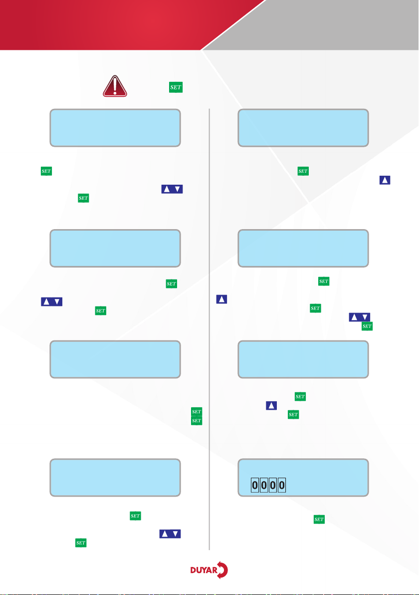
Press the button in the General Settings menu, the
text Voltage On starts to flash and the value next to it
can be changed with the help of the arrow keys,
after the change is completed, by pressing the
button value is memorized. arrow keys are used
to find the parameter we want to change and when
the parameter is hovered, the key is pressed and
the text starts to flash, in this case the value is changed.
Voltage On: It is the voltage-on time setting. Waiting
time for automatic reset when the voltage values
measured when the system is in fault state due to
voltage error again within the desired limits.
Voltage Off: It is the voltage error tripping time setting.
When the measured voltage values go out of the set
values, it is the waiting time to turn off. It is necessary
in order not to take the pump off frequently in case of
instantaneous fluctuations.
SSR On: It is the liquid level (SSR) reset time setting. It is
the waiting time setting for automatic reset when the
water comes back when the system is in a malfunction
state due to dehydration.
SSR Off: It is the liquid level error tripping time setting.
When the water in the tank or well runs out, it is the
time to wait for the circuit to go out.
Demerage: Inrush current time setting. During the
period set here, the currents drawn from the moment
the pump starts up for the first time cannot be
compared with the set values.
Current Delay: Current fault trip time setting. When
the lower or upper current goes out of the set value, the
time setting for stopping the motor is set in seconds.
Start Delay: When the signal comes from the pressure
switch, the pumps are activated as late as the set time
for the time set here.
Stop Delay: When the signal from the pressure switch
is lost, it turns off the pumps within the set time.
Reset Time: Reset time setting allows us to set how
long it waits for the system to be activated again when
it fails due to current error. The setting is in seconds.
Reset-2: It is the reset number setting.
Salt: Ability to limit the number of pumps on and off
in 1 hour.
Pump Change: It is the changeover time setting for
pumps operating in circulation mode.
The automatic test setting is pressed, the button is
pressed, the test factory setting is passive, when we press
the set button, the Test text starts to flash. appears as
a clock. The run time setting allows us to set how long
(seconds) the pump will run. Pump operation active or
passive option is selected by pressing the arrow key
and the key is pressed, it automatically saves.
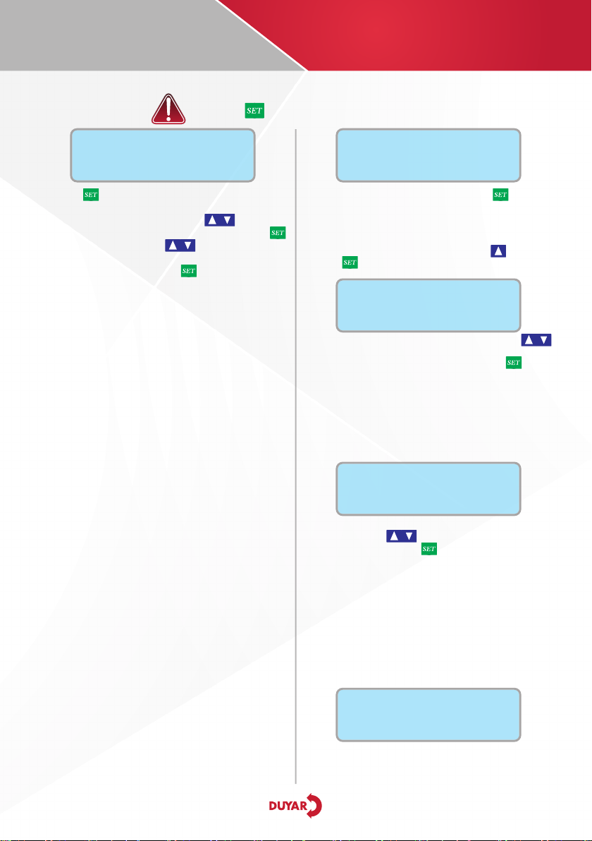
Transmitter Setting is adjusted with the help of
arrow keys while the text "Sensor available or No sensor"
is flashing, and it is stored by pressing the key. If
the sensor is selected, the system now works with the
transmitter and does not read the pressure switch input.
Maximum: Pressure transmitter maximum (label)
value, enter 16 bar for 16 bar transmitter.
Set Valuei: Pump stop set pressure value.
Hys Value: Pressure hysteresis adjustment. For
example, if our set pressure is 8.0 bar hysteresis 1.0,
then 1 pump works at 7.0 bar, 2 pumps work at 6.0
bar, and 3 pumps at 5.0 bar.
Operation Mode Selection, operation selection is made
with the help of arrow keys according to the
pump used. Press the button and it will save
automatically.
Hydrophore: Standart hidrofor motorlarında bu mod
seçilmelidir.
Hydrophore + Ptc: If there is PTC protection in booster
pumps, this mode should be selected. Otherwise, PTC
protection will not do..
P + Joker: It is the choice of 1 main and 1 wildcard in fire systems.
Waste Water: This mode should be selected for
wastewater pumps. When this mode is selected, water
leakage and Ptc inputs are active.
Waste Water Stop Fit: In the selection of waste water
with stop floater, water leakage and Ptc inputs become
active and the system stops according to the stop floater.
Floater / SSR selection is the float or SSR electrode
protection selection setting of the device. Selection
is made with the help of the arrow key and saved by
pressing the set key.
General Settings
Voltage On = 05
Auto Test Settings
Test = Active
Floater / SSR Secim
Floater
Transmitter Set
There is Sensor
Operation Mode Select
Hydrophore
6. SETTINGS MENU
Press the button to enter the menu.

HYDROPHORE
CONTROL PANEL
INSTALLATION, MAINTENANCE and OPERATION GUIDE
7
7. TECHNICAL DETAILS TABLE
Operating Voltage (Un)
Operating Frequency
Working Power
Operating Temperature
Voltage Measurement Range
Measurement Accuracy
Delay Time Setting
Indicator
Connection Style
Ignition
Connection Insulation
Assembly
Protection Class
Working Altitude
PART NAME
230 V - 380 VAC
50 / 60Hz
<6VA
-20°C to 55°C
10 - 500 V AC
%±1
1-30 sec.
2 X 16 LCD Screen and Leds
Terminal Connection
5 A / 250 VAC Resistive Load
2.5 kV
On the Pump or On The Wall
Ip55
<2000 meter
TECHNICAL DETAILS
8. CONNECTION DIAGRAM
14
11 12 13
10
9
ERR
L1
L2
L3
MAIN
380V AC
50-60Hz.
PRESSURE
SWITCH
FLOATER
678
34 5
21
CONTROL PANEL
SELENOID
UV W
X Y Z
17 18
16
15
N
COM
Figure-1: 1 Pump Booster Connection Diagram

8
HYDROPHORE
CONTROL PANEL
INSTALLATION, MAINTENANCE and OPERATION GUIDE
8. CONNECTION DIAGRAM
14
11 12 13
10
9
ERR
L1
L2
L3
MAIN
380V AC
50-60Hz.
PRESSURE
SWITCH
FLOATER
678
34 5
21
CONTROL PANEL
SELENOID
UV W
X Y Z
17 18
16
15
N
COM
UV W
X Y Z
14
11 12 13
10
9
ERR
L1
L2
L3
MAIN
380V AC
50-60Hz.
PRESSURE
SWITCH
FLOATER
678
34 5
21
CONTROL PANEL
SELENOID
UV W
X Y Z
17 18
16
15
N
COM
UV W
X Y Z
UV W
X Y Z
Figure-2: 2 Pump Booster Connection Diagram
Figure-3: 3 Pump Booster Connection Diagram

HYDROPHORE
CONTROL PANEL
INSTALLATION, MAINTENANCE and OPERATION GUIDE
9
9. WARRANTY
Principles specified in this user guide, instructions, standards-compliance No other institution
and contact an authorized service maintenance, repair or other reasons, provided that
untreated The materials used on the control panel manufacturer; workmanship, assembly and
manufacturing defects user Company is subject to the terms of warranty.
Outside the Remaining Extent of Warranty Conditions :
1. Warranty terms and conditions only on the invoice in writing the product/products covers.
2. User errors, failures and damages that occur.
3. Misuse damages use and malfunctions.
4. Incorrect installation, incorrect or incomplete damage and faults caused from installation made.
5. Shipping, vibration, storage, physical collisions, damage and malfunction caused by chemical
factors, and environmental conditions.
6. Fire, lightning, floods, earthquakes and other natural disasters damage and malfunctions.
7. Failures and damages caused intentionally harming.
8. Incompatibility or lack of damage to the cables used in electrical installations and faults.
9. In the Product's user guide for damage and malfunctions occurring against the issues.
10. The interventions given to the product by unauthorized persons to the product warranty expires.
Caution
Please obey this user guide and following subjects for safety use.
●All energy should be cut-off while device connecting to panel.
●Solvent or similar matter use when cleaning.
●Check the connections according to connection diagram.
●Defective device should repair only producer company or authorized seller.
The company or authorized seller is not responsible for bad result which born
of these unperformed conditions.

2021.11.1
WE ARE SENSITIVE TO LIFE
Table of contents
Other DUYAR Control Panel manuals