Cooper Scantronic 8136UK-50 Installation guide

HARDWIRED CONTROL
PANEL
INSTALLATION AND
PROGRAMMING GUIDE
Leading the way in security
8136UK-50/75

8136 Hardwired Control Panel Installation and Programming Guide.
© Scantronic Ltd. 2000
Every effort has been made to ensure that the contents of this book are correct. However, neither the authors nor
Scantronic accept any liability for loss or damage caused or alleged to be caused directly or indirectly by this book.
The contents of this book are subject to change without notice.
Printed and published in the U.K.

Contents
1. Overview
2. Technical Specification
3. Installation
4. Programming
5. Programming for IDIS
. Programming Examples
7.Programming Reference
8. Communications
9. Testing
10. Fault Finding
Index

ii 496310
How To Use This Book
This book is divided into the following sections:
1: Overview gives a brief introduction to the 8136.
2: Technical Specification lists the physical capabilities of the system, and
gives part numbers for compatible equipment.
3: Installation provides step by step instructions for physically installing the
8136 end station and its keypads, wiring Fully Supervised Loop (FSL) sen-
sors, connecting sounders, and wiring IDIS devices.
4: Programming describes how to enter and leave programming mode on
the 8136.
5: Programming for IDIS provides details on programming IDIS devices.
This section also contains instructions on how to use the handheld IDIS
Programmer for programming and fault finding IDIS devices.
6: Programming Examples gives a set of detailed examples to show how to
program various features of the 8136.
7: Programming Reference lists the factory defaults for programming, and
gives detailed information about the meaning of other programming param-
eters, for example zone types and output types.
8: Communications provides installation and programming instructions for
using both the built-in and add-on communicators.
9: Testing gives step by step instructions for using the built-in testing com-
mands.
10: Fault Finding lists common error messages that may be encountered
during programming, and suggests causes and corrective actions. This
section also contains detailed instructions for fault finding on IDIS systems.

496310 iii
Contents
1. Overview ................................................................................................. 1
Control Unit .................................................................................................. 2
Keypads ....................................................................................................... 3
The 931 Keypad ..................................................................................................................... 3
The 930 Low Profile Keypad .................................................................................................. 3
2. Technical Specification .......................................................................... 5
General .................................................................................................................................. 5
Power Supply ......................................................................................................................... 5
Output Protection ............................................................................................................. 5
Battery ............................................................................................................................. 5
Keypad Wiring ........................................................................................................................ 5
FSL Zone Wiring .................................................................................................................... 6
IDIS Zone Wiring .................................................................................................................... 6
Software Limits ...................................................................................................................... 6
Compatible Equipment ........................................................................................................... 6
3. Installation .............................................................................................. 9
Fitting the Control Unit ............................................................................... 10
Battery ................................................................................................................................. 11
Wiring to the Mains .............................................................................................................. 11
Keypads ..................................................................................................... 12
Keypad Address ............................................................................................................ 12
Enabling/Disabling Keys, Display and Sounder ............................................................. 12
Display Test (Optional) ................................................................................................... 13
Fitting a 931 ......................................................................................................................... 13
Fitting a 930 ......................................................................................................................... 14
Wiring ......................................................................................................... 15
Wiring Keypads .................................................................................................................... 16
Wiring FSL Detectors ........................................................................................................... 16
Wiring External Sounders .................................................................................................... 18
Internal Sounders in Multi-Partition Systems ................................................................. 19
Wiring Keyswitches to FSL Zones ....................................................................................... 19
Wiring a Lighting Control Zone ............................................................................................. 21
Connecting a Printer ............................................................................................................22
Wiring IDIS Detectors................................................................................. 23
IDIS Wiring Layout ............................................................................................................... 23
Maximum IDIS Cable Lengths .............................................................................................. 25
Wiring IDIS Devices .............................................................................................................26
IDIS Switched I/O Devices ................................................................................................... 27
Wiring Non IDIS Detectors to the IDIS Bus .......................................................................... 27
IDIS Module ................................................................................................................... 27
IDIS Line Interface Modules (LIMs) ............................................................................... 27
Wiring Keyswitches to IDIS Zones ....................................................................................... 29
Wiring a Lighting Control Switch to an IDIS Zone ................................................................. 30
Initial Power Up .......................................................................................... 31
Battery Only (Kick Start) ...................................................................................................... 31
Power-Up With Mains ........................................................................................................... 31

iv 496310
4. Programming ........................................................................................ 35
Programming Mode .............................................................................................................. 35
Finding Menu Items ....................................................................................................... 35
Changing Menu Items .......................................................................................................... 36
Correcting mistakes ....................................................................................................... 36
Entering Text ........................................................................................................................ 36
Leaving Programming Mode ................................................................................................ 37
To Return to the ‘All Level Unset Mode’ From Programming .......................................... 37
Engineer Reset .................................................................................................................... 38
Resetting User and Installer Codes ..................................................................................... 38
Return to Factory Defaults ................................................................................................... 39
5. Programming for IDIS .......................................................................... 41
IDIS Programming Errors ..................................................................................................... 43
944 Handheld IDIS Programmer ................................................................ 44
Switching the Programmer On and OFF .............................................................................. 45
General Controls .................................................................................................................. 45
Changing the Display Timeout ....................................................................................... 45
Checking the Programmer Power Source. ..................................................................... 45
Changing Language ...................................................................................................... 45
Programming IDIS Devices .................................................................................................. 46
Leaving Programming .................................................................................................... 47
Using the Programmer for IDIS Diagnostic Testing .............................................................. 47
Running Diagnostic Tests .............................................................................................. 47
Current Readings .................................................................................................... 48
Leaving Diagnostic Tests ............................................................................................... 48
6. Programming Examples ...................................................................... 49
Example 1: Full Set and Three Part Sets ................................................... 50
Example 2: Two Partitions .......................................................................... 54
Example 3: Commercial with Four Partitions .............................................. 57
Example 4: Four Partitions with Common Area .......................................... 60
Example 5: Zones and Expander cards...................................................... 63
Example 6: Keyswitches ............................................................................. 64
Example 7: Names ..................................................................................... 66
Zone Names ........................................................................................................................ 66
Area Names ......................................................................................................................... 66
Account Name ..................................................................................................................... 66
Installer Information .............................................................................................................. 66
Example 8: Zone Omission ........................................................................ 67
Example 9: Lighting Control ....................................................................... 68
Example 10: Technical Alarms.................................................................... 70
User Facilities ............................................................................................. 71
Operating the System .......................................................................................................... 72
Installer Setting .............................................................................................................. 73
7. Programming Reference ...................................................................... 75
Factory Defaults ................................................................................................................... 75
System Users ......................................................................................................... 75
Installer programming .............................................................................................. 75

496310 v
Menu Options ............................................................................................. 76
Menu 01 - Display Panel Version Number ............................................................................ 77
Menu 04 - Test Options ........................................................................................................ 77
Menu 09 - Print Options ....................................................................................................... 77
Menu 11 - Edit Name (Account Name) ................................................................................. 77
Menu 21 - Zone Expander Options ...................................................................................... 77
Menu 22 - IDIS Programming ............................................................................................... 77
Menu 31- Zone Names ........................................................................................................ 78
Menu 32 - Zone Types .......................................................................................................... 78
Menu 32 - Zone Attributes .................................................................................................... 82
Menu 33 - IDIS Initialisation ................................................................................................. 83
Menu 34 - Area Names ........................................................................................................ 83
Menu 35 - Program Partitions ............................................................................................... 83
Menu 41 - Level Allocation ................................................................................................... 84
Menu 42 - Exit Modes .......................................................................................................... 84
Menu 43 - Level Entry Time ................................................................................................. 85
Menu 44 - Level Flex Zones ................................................................................................. 85
Menu 45 - Level Alarm Response ........................................................................................ 85
Menu 46 - Level Re-Arm Response ..................................................................................... 86
Menu 47 - Keypad Allocations .............................................................................................. 86
Menu 48 - Common Area ..................................................................................................... 87
Menu 49 - Common Area Full Set Link ................................................................................. 87
Menu 51 - Output Types ....................................................................................................... 87
Menu 52 - Program Sounders .............................................................................................. 91
Menu 53 - Partition Bell Times ............................................................................................. 91
Bell Delay Always Used ................................................................................................. 91
Bell Delay Override Allowed .......................................................................................... 92
Menu 54 - Entry / Exit Tones ................................................................................................ 92
Menu 55 - Lighting On Time ................................................................................................. 92
Menu 56 - Tamper Return ..................................................................................................... 92
Menu 61 - Installer Information ............................................................................................. 92
Menu 62 - PA Response ...................................................................................................... 93
Menu 63 - Line Fault Response ........................................................................................... 93
Menu 64 - Allow Zone Omits ................................................................................................ 94
Menu 65 - System Reset ..................................................................................................... 94
Menu 66 - Serial Port ...........................................................................................................95
Menu 67 - Miscellaneous Options ........................................................................................ 96
Menu 68 - Battery Load Test ................................................................................................ 98
Menu 71 - Communication Options ...................................................................................... 99
Menu 72 - Program Phone Numbers ................................................................................... 104
Menu 73 - Downloader Options ........................................................................................... 105
8. Communications ................................................................................ 107
Introduction ......................................................................................................................... 107
Telephone Line ............................................................................................................. 107
Three Way Calling .................................................................................................. 107
Line Monitoring ............................................................................................................. 108
Test Calls ...................................................................................................................... 108
Statutory Information ........................................................................................................... 108
Application .................................................................................................................... 108
Compatible PABXs ....................................................................................................... 108
Approval ....................................................................................................................... 108
REN .............................................................................................................................. 109

vi 496310
Installation ................................................................................................ 109

Safety notice ....................................................................................................................... 109
Fitting a Plug On Communicator ......................................................................................... 110
9076-01 Interface .......................................................................................................... 111
9076-02 Interface .......................................................................................................... 111
Connecting the Telephone Line ........................................................................................... 111
Programming for Central Station .............................................................. 113
Communications Options (Menu 71) ................................................................................... 113
Phone Numbers and Account Numbers (Menu 72): ............................................................114
Line Fault Response (Menu 63). ......................................................................................... 115
Miscellaneous Options (Menu 67) .......................................................................................115
Working With <DOWNLOADER> ............................................................. 116
Connecting to a Remote PC for the First Time (Menu 66) ................................................... 118
Connecting a Local PC to Use Downloader (Menu 66). ...................................................... 119
"Call Out" to a Downloading Computer ............................................................................... 120
9. Testing ................................................................................................. 121
Panel Version Number (Menu 01) ........................................................................................ 121
Test Options (Menu 04) ....................................................................................................... 121
To Select a Test: ........................................................................................................... 121
Walk Test ...................................................................................................................... 122
Output Test ................................................................................................................... 122
Sounder Test ................................................................................................................ 123
Zone Status .................................................................................................................. 123
FSL Zone Current Readings .................................................................................. 124
IDIS Zone Status ....................................................................................................124
IDIS Zone Current Readings .................................................................................. 125
Aux Voltage, Battery Charge, PSU Load, and Battery Test ........................................... 125
Printer Options (Menu 09) ................................................................................................... 126
The Event Log .............................................................................................................. 126
Viewing Event Log From the Keypad ............................................................................ 127
Using the Test Zone Attribute .............................................................................................. 127
10. Fault Finding .................................................................................... 129
General Faults ..................................................................................................................... 129
No response from the keypad keys. ............................................................................. 129
No exit/entry tones from remote keypad .......................................................................129
Manual Connect from the remote PC fails to operate. ...................................................129
Cannot remotely Set/Unset system .............................................................................. 129
Error Messages ........................................................................................ 129
General Error Messages .....................................................................................................129
907 Intelligent Power Supply ...............................................................................................130
Configuration Checking Error Messages ............................................................................. 131
FSL Zone Status Error Messages .......................................................................................133
IDIS Error Messages .......................................................................................................... 133
IDIS Fault Finding ..................................................................................... 133
Simple Test Method ............................................................................................................. 134
Thorough Test Method .................................................................................................. 136
Improving the Voltage Drop ................................................................................................. 137
Fitting a PSU ....................................................................................................................... 138
Electrical Noise ................................................................................................................... 139
Index ........................................................................................................ 141

496310 1
1. Overview
1. Overview
The 8136 is a programmable Alarm System that can be expanded up to 136
zones and is suitable for large residential and business premises.
The system comprises an control unit in a shielded case, and up to fifteen
separate keypads. A basic 8136 provides connections for up to eight Fully
Supervised Loop (FSL) zones, and four programmable outputs. In addition,
the 8136 has a built in Digital Communicator (modem) that can be used to
signal to a remote Central Station, and for remote control from a PC.
By installing an eight zone FSL Expander card the system can provide a total
of 16 FSL zones. Alternatively, the 8136 can use Individual Detector Identifi-
cation System (IDIS) expander cards to provide either 32 or 128 additional
IDIS zones.
IDIS is the proprietary three wire point detector identification system devel-
oped for Scantronic Limited. Each IDIS zone can connect an IDIS detector
or, by using an IDIS interface module, a standard detector and output. IDIS
minimises wiring costs since all detectors can share a single 3-wire cable.
The 8136 also provides pins for fitting a plug-on communication device, and
will work with any device that complies with the Scantronic plug-on footprint.
The 8136 software provides a flexible installation that can meet many differ-
ent needs. A system can be partitioned by installer programming so that it
can provide up to four sub Alarm Systems using one set of hardware. The
8136 can provide for up to 95 identified users, and each user can be limited
to specific partitions. The 8136 allows users to set the system to four different
security Levels, which can be programmed by the installer. Individual zones
can be programmed as Flexi-Zones®, which change behaviour depending on
which security Level is set.
The installer can program the system from a keypad, which provides a 32
character Liquid Crystal Display (LCD) giving plain text responses to com-
mands. The programming interface is arranged into a set of numbered
menus that lead the installer through the installation process.
Alternatively, the installer can use Scantronic <Downloader> software on a
remote PC to program the system. <Downloader> also provides on-line
control. Using <Downloader> can shorten the time an installer spends on
site, and reduce the number of visits to a user site for maintenance and
resets.
Before installing an 8136 system make sure you are fully familiar with the
functions of the control unit and the installation procedures described in this
manual.

2 496310
1. Overview
Control Unit
Figure 1 below shows the control unit PCB. Use the diagram to familiarise
yourself with the location of the connectors, reset and kick start pins.
Figure 1. Control Unit PCB
Plug-on
Communicator
FSL
Expander Card
942 IDIS
Expander Card
941 IDIS
Expander Card
OR
OR
Communications
LED
Telephone
Connector
Power LED
21VAC Supply
from Transformer
Battery
Connector
Kick Start
Pins
RST Pins
ROM Socket
Comms Test
Pins
Serial Port
Lid Anti-Tamper
Main connector
block
Printer Connector
RJ11 phone
connector

496310 3
1. Overview
Keypads
The 931 Keypad
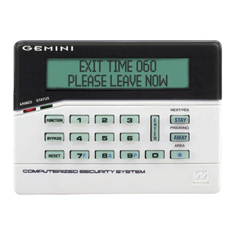
The 8136 uses the 931 low profile keypad, shown in Figure 2.
Figure 2. 931 Operator Controls and Displays
The keypad provides a 32 character super twist LCD display, green power
LED, and four red Level status LEDs.
The 930 Low Profile Keypad
The 930 contains the same PCB as the 931, but in an alternative style case.
Figure 3. 930 Operator Controls and Displays
Level A to D LEDs
(Set or Unset)
Power
Keyboard with
backlit soft rubber
keys
Optional programmable
panic alarm keys. Press
keys 1 and 3 together
Scroll and Level
setting keys
Edit keys
Optional programmable
control function keys.
Press keys 7 and 9
together
Menu and Enter keys
32 Character plain text
Liquid Crystal Display

4 496310
1. Overview
Figure 4 shows the keypad PCB used in the 930 and 931. Note the position
of the Test and Prog switches, and the keypad sounder volume control.
Prog
Test
1
2
Figure 4. Keypad PCB.
Back of display
Sounder
Key area
Micro
Connector
Sounder Volume
Control
Prog and Test

496310 5
2. Technical Specification
General
Operating temperature = -10º to +55ºC
Humidity = 80% RH
Dimensions (control unit) = h x w x d 310 x 385 x 95mm
Weight (control unit) = Approximately 7Kg
Power Supply
System Power Supply
(Ambient Temp. 20 º C) = 1,250 mA
With the system quiescent, this supply is used as follows:
8136i control unit = 150mA
Each Remote Keypad = 60mA
8 Zone Expander = 20mA
32 channel IDIS Expander = 20 mA
128 channel DIS Expander = 100mA
The remaining current is available for recharging the battery, supplying IDIS
devices though the IDIS expander, and supplying attached devices through
the 12V Aux terminals on the main connector.
Output Protection
Self resetting thermal Polyswitches protect outputs at the following levels:
12v Aux = 1,350mA
Keypad 12V = 500mA
Siren = 750mA
Batt (reverse connection) = 2,500mA
OP1, OP2, OP3, and OP4 are voltage free, single pole relay contacts rated
24VDC @ 3A.
Battery
Recommended Standby
Battery = 12 Volt, 7.0AH (min), 17AH (max) re-
chargeable lead-acid, Gel Type battery
Battery Space = h x w x d 190 x 205 x 75mm
Keypad Wiring
Recommended maximum distances for the remote keypads from the control
unit, using standard alarm cable is 300 metres per branch for a star configu-
ration.

6 496310
2. Technical Specification
For a daisy chain configuration the maximum length must take account of
the number of keypads sharing the cable. In general, a single keypad can be
connected at the end of a maximum of 300 meters of standard cable. If you
wish to connect more keypads the cable must be shorter, or the 0V wire must
be thicker. Ensure that at the last keypad the voltage between 0V and 12V
wires is no less than 10.5V.
FSL Zone Wiring
The recommended maximum distance for FSL zones using standard alarm
cable is 300m.
IDIS Zone Wiring
The maximum cable length for a single IDIS loop, including spurs, is 500m.
See "3. Installation - Wiring IDIS Detectors - Maximum IDIS Cable Lengths"
for a more detailed discussion.
Software Limits
The 8136i can support:
• From one to four Partitions.
• One to four Levels.
• One to fifteen keypads.
• Eight Areas in total. Note that two Partitions cannot share an Area.
• A minimum of eight zones provided by the control unit PCB up to a
maximum of 136 zones with the aid of an IDIS Expander Card.
• A minimum of four outputs provided by the control unit PCB up to a
maximum of 132, with the extra 128 provided by IDIS modules or
LIMs.
• Six Flexi-Zones per Level.
• 95 User codes, including one Supervisor.
• Up to 500 records in the event log.
See "6. Programming Examples" for more details.
Compatible Equipment
941 Single Loop IDIS zone expander card
942 Four Loop IDIS zone expander card
943 8 zone FSL plug-on Zone Expander
930 32 character LCD Remote Keypad (new style large keys
)
931 32 character LCD Remote Keypad, new style case.

496310 7
2. Technical Specification
947 Portable printer ( Battery powered ) and power supply
unit
949 Wall Mounted Printer Bracket
956 Scantronic high speed <Downloader> Windows™ based
software
951 Printer lead (supplied with 947 Printer)
9040 16 Ohm internal sounder
9056 Plug-on Digital Communicator
Plug-on RedCare STU (manufactured by others)
9076-01/2 Signalling Interfaces
901 Wired IDIS Module (Pack of 5)
903 Mains switching (AC) relay I/O IDIS boxed interface
904 Low voltage relay I/O IDIS boxed interface
907 IDIS with power supply
908 IDIS LIM (8 x 4 wire CC or 2 wire FSL inputs, 8 x 0C
outputs (100mA each))
915/916 IDIS PIRs
920 IDIS Twintech (multi-beam domestic)
921 IDIS Twintech (multi-beam commercial)
922 IDIS Twintech (long range commercial)
923 IDIS Twintech (360º ceiling mount)
944 IDIS Hand-held Programmer
8136EUR-02 17AH Large Capacity Battery Kit
8136UK-75 RedCare Ready Kit

8 496310
2. Technical Specification

496310 9
3. Installation
3. Installation
These installation instructions assume that you have already identified the
locations of the detectors, keypads, sounders and control unit, and run
suitable cable to each position. Then:
1. Install the control unit.
2 Address, install and connect at least one LCD keypad.
3. Install all conventional detectors, external and internal sounders, etc.
Address and install all remaining keypads.
Note: You must address each keypad BEFORE connecting it to the control unit.
4. Fit Expander Cards as necessary.
5. Connect all system wiring to control unit.
When installing an IDIS based system you must allow for programming the
IDIS devices. The control unit cannot program individual IDIS devices when
they are all connected together on the IDIS bus wiring.
6. Apply power for the first time.
7. Program any IDIS modules or sensors with their individual zone
numbers.
8. Install all programmed IDIS units.
9. Program the rest of the system as required.
10. If necessary fit and program a communicator.
11. Carry out full installer tests.
12. Hand over system to User(s).

3. Installation
10 496310
Fitting the Control Unit
1. Remove the screws from the control unit cover and lift the cover off.
Figure 5 shows the inside of the control unit.
20 mm
Cable Entries
Keyhole
knockouts
20 mm
Cable Entries
Lid Tamper Switch
Transformer
Mains Fused terminal
(Euro 20mm type)
Space for a 17Ah battery
Fixing hole
Fixing hole
Keyhole
knockouts
Fixing hole
Main PCB
Figure 5. Control Unit Internal Layout
2. Note the positions of the 20 mm cable entries.
Warning
Do not feed mains cables and low voltage circuit
and sounder cables through the same entry.
Always keep separate.
Caution Where cables enter directly through a metal enclosure, always
prepare entry with Grommets or suitable cable entry sheathing.
3. Position the back box with the printed circuit board to the left. Mark the
centre slotted fixing hole, then drill and plug the wall.
Caution Do not drill holes with the control unit in position. The resultant
dust and vibration may damage the PCB components and may
invalidate warranty.
4. Screw a pan-head No.10 screw (Twin-fast or normal screw) into the
plugged hole. Relocate the control unit case back on the centre screw
hole, then continue to mark the two lower fixing screws. Remove the

496310 11
3. Installation
control unit, then drill and plug the two bottom holes. Continue to fix the
control unit using not less than No. 10 pan head screws.
Battery
The control unit has space for a 17Ah sealed Lead Acid battery. See Figure
5 for location. When fitting a 17Ah battery use the bracket provided to
secure the top of the battery to the back of the case. This will prevent the
weight of the battery distorting the case.
Caution Do not connect battery at this point.
Wiring to the Mains
The mains supply to the control unit is connected via the 3 way ‘Euro Type’
fuse block located to at the top right hand side of the control unit rear casing.
To comply with BS4737, the supply should come from an un-switched, fused
spur unit fitted with a 3A fuse. Secure the mains cable to the anchor point on
the case using a suitable cable tie. All electrical connections should be
carried out by a qualified electrician and must comply with the current IEE
Wiring Regulations: 16 Edition, Appendix 5 - Standard Circuit Arrangement.
Ensure the mains supply has a proven earth.
To Control Panel
Transformer
315mA
N
(L)P
240Vac
Figure 6. Control Unit Mains Connection

3. Installation
12 496310
Keypads
NOTE: The Installer must program an identification number into the NVM
chip on each keypad before connecting it to the system. Each keypad in a
system must have a different address number to ensure that the control unit
can correctly identify them. The keypad sounder, back-light and LCD display
can also be tested and setup at this stage.
Keypad Address
1. Open the keypad case and identify the Prog and Test switches, see
Figure 4.
2. Set the ‘Prog’switch on the keypad PCB to ‘On’and the ‘Test’switch to
‘Off’.
3. Connect the 0V and +12v terminals to a 12 volt DC supply, for example
a charged battery.
The display shows the software number of the keypad. Take note for
future reference.
4. Press ‘Menu’.
The display shows the current keypad address, for example: 1: 1
5. If necessary change the keypad address by pressing the A (up arrow)
or B (down arrow) keys. Note that the highest address is 15. For
example, change the address to 2 for the second keypad. Note that for
931 keypads with software V2.03 or earlier you must enter a number
between 1 and 4. These keypads do not accept addresses beyond 4.
The display shows the new keypad address. 1:2
Enabling/Disabling Keys, Display and Sounder
6. Press ‘Menu’.
The display shows the status of the keypad sounder: 0 for sounder ‘ON’
or 1 for sounder ‘OFF’, for example: 2: 0
7. Change the keypad sounder status as required by entering 0 or 1.
(The keypad sounder is normally left at ON = ‘ZERO”).
8. Press ‘Menu’.
The display shows the current status of the keypad back-light: 0 for
timed or 1 for back-light always ‘ON’, for example: 3: 1
9. Change the back light status as required by entering 0 or 1
10. Press ‘Menu’.
The display shows the current status of the keys:
0 for Active or 1 for Inactive, for example: 4: 0
This manual suits for next models
1
Table of contents
Other Cooper Control Panel manuals

Cooper
Cooper EASICHECK EC2001 User manual

Cooper
Cooper DF6000 User manual

Cooper
Cooper CF3000 User manual

Cooper
Cooper CF1100 User manual

Cooper
Cooper CF2000 User manual

Cooper
Cooper Scantronic 500r+ Installation guide

Cooper
Cooper Scantronic 9850 Installation guide

Cooper
Cooper Kyle Form 4C User manual

Cooper
Cooper SAFEPATH SP4-LOC User manual

Cooper
Cooper Scantronic 500r+ User manual