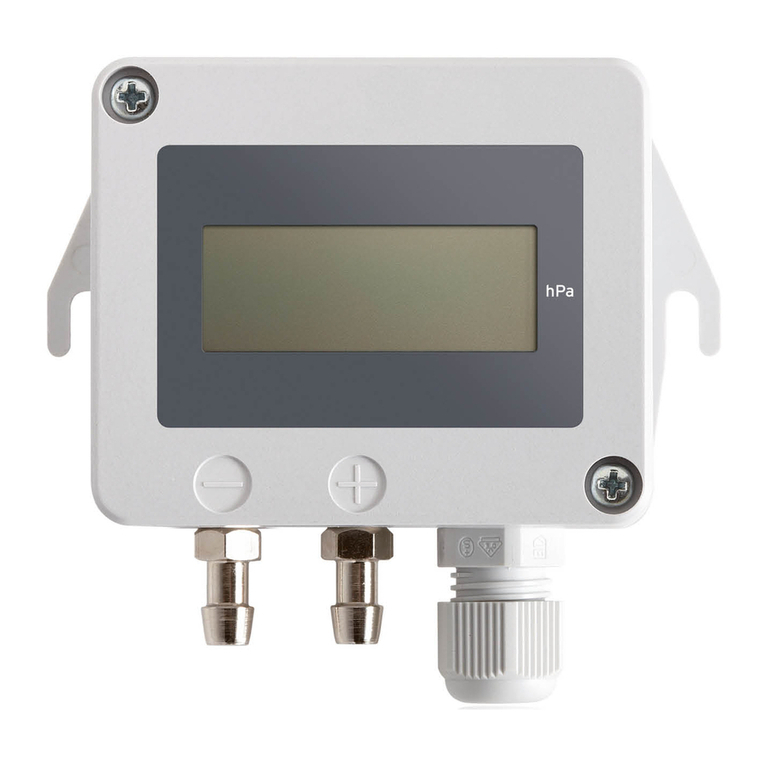
FSM Feel FC User manual

Version: 1 FSM AG │
Erich-Rieder-Str. 2 │ 79199 Kirchzarten www. sm.ag
Operating instructions eel FC Page 1 o 7
Instruction Manual
CO2 Transmitter eel FC
Online Version Datasheet
1 Introduction
1.1 Notes on the operating instructions
These operating instructions are intended to ensure optimum installation, commissioning, operation and
maintenance o the device and must be read prior to these actions. Keep this documentation handy and
accessible to every user in order to be able to re er to it i necessary. I any di iculties should nevertheless
arise during commissioning or operation, please do not make any unauthorized modi ications to the device.
Doing so could jeopardize your warranty claim. In such cases, please contact us immediately:
FSM AG | Erich-Rieder-Straße 2 | D-79199 Kirchzarten | Tel: + 9 7661 9855 0 | Mail: [email protected]
1.2 Intended purpose and foreseeable misuse
The eel FC CO2 transmitter is used to record the measured variable CO2 and convert it into a proportional
measuring signal. The device may only be used in the speci ied measuring range. Do not use the device in
potentially explosive atmospheres. No liability is accepted or damage resulting rom improper use. In this
case, warranty claims become invalid. Unauthorized structural modi ications as well as additions or
conversions to the device are prohibited.
2 Notes for your safety
To avoid danger to all persons involved, this device must only be installed and commissioned by quali ied and
trained personnel. Furthermore, persons using this device must take measures to protect themselves rom
direct contact with the live parts and must have read and understood these instructions.

Version: 1 FSM AG │
Erich-Rieder-Str. 2 │ 79199 Kirchzarten www. sm.ag
Operating instructions eel FC Page 2 o 7
3 Installation and startup
3.1 Mounting
The unit is mounted on the wall using the snap-in rame supplied. The mounting rame is attached to the wall
with dowels and screws. The eel transmitter is then snapped into the mounting rame. Mount the device on
a vertical, smooth sur ace make sure that the device is not mounted in the immediate vicinity o sources o
inter erence or heat.
3.2 Connection control and display elements
The igure below shows all connection, control and display elements o the transmitter board and describes
their unctionality.
Figure 1 Connection, control and display elements
(1) DIP-Switches: or con iguration o di erent parameters like measuring range or output signal
(2) Display plug: Connector plug to display cable
(3) Slide switches: or switching the outputs between current to voltage output

Version: 1 FSM AG │
Erich-Rieder-Str. 2 │ 79199 Kirchzarten www. sm.ag
Operating instructions eel FC Page 3 o 7
(4) Clamps for Input and Output: Push-in terminals or power supply and output signals
(5) LED: multicolor status LED or displaying operating and error states
(6) Buttons: Pushbutton or adjustment at de ined adjustment points
(7) USB Plug: USB connector or connecting the transmitter to a PC
(8) Sensor plug: Connecting plug to a sensor tube
(9) CO2-Sensor: Sensor element or measuring the CO2 concentration
3.3 Connection
Feed the input and output lines through the cable glands attached to the housing and clamp them to the
terminals provided (see 3.2 ( ) Clamps for Input and Output):
Line
Clamp
Supply
+ / L
V+
Supply
-
/ GND
GND
Output CO2 + (with analog variant) | Modbus A (with RS485 variant)*
OUT
1
Modbus B (with RS485 variant)*
OUT 2
Output Open Collector 1 optional
(2 VDC
and
1A
,
not short circuit proof
)
OUT 3
Output Open Collector 2 optional
(2 VDC
and
1A
,
not short circuit proof
)
OUT
4
Output
-
/ GND
GND
*On the last device in the Modbus topology, the terminating resistor must be set via switch T (position on the
right). The detailed Modbus protocol can be downloaded via the ollowing link:
https://measure. sm.ag/ ileadmin/Messtechnik-PDFs/Feel_Modbus_Protokoll_english.pd
Connection diagram Open collector to relay: Connection diagram Open collector to SPS:
4 Setting and configuration via DIP switch
Note: A con iguration o the parameters via DIP switch (see 3.2 (1) DIP switches) can only be done i the DIP
switch 12 is set to OFF.

Version: 1 FSM AG │
Erich-Rieder-Str. 2 │ 79199 Kirchzarten www. sm.ag
Operating instructions eel FC Page 4 o 7
4.1 Setting the measuring range
You can adapt the respective desired measuring range o the di erent sensors to your application via DIP
switches (see 3.2 (1) DIP switches).
The respective setting options can be ound in the ollowing table:
Scaling of the measuring range
Variant 5000 ppm
DIP switch position 5
0… 5000 ppm OFF
0… 2000 ppm ON
Note: For the variant 0... 2000 ppm the possibility of a measuring range scaling does not exist.
4.2 Setting the output signal
You can adapt the respective desired analog output to your application via slide switch S1 (see 3.2 (3) Slide
switches) and DIP switch 7 (see 3.2 (1) DIP switches). The respective setting options can be ound in the
ollowing table:
Output Output signal Slide switch position DIP switch position 7
CO2 (1)
0… 10 V S1 rechts OFF
2… 10 V S1 rechts ON
0… 20 mA S1 links OFF
4… 20 mA S1 links ON
5 Setting and configuration via software
Customer so tware is available or the eel transmitter, which can be used to con igure various parameters.
Proceed as ollows:
5.1 Installation of the software
• Download the " eel con iguration so tware" in the download area o the web page o the eel series o
transmitters: https://measure. sm.ag/en/home/products/multi-transmitter/ eel-multi
• I you do not have .NET 6.0 Desktop Runtime (v6.0.12) pre-installed, install it be ore using the
application: (Download link .NET 6.0 Desktop Runtime (v6.0.12))
• Open the application "Con iguration so tware eel (exe)".
• Under certain conditions, a Windows popup window will appear warning about using an unknown
so tware. Click on "More in ormation" and the button "Run anyway".
5.2 Commissioning a feel transmitter
5.2.1 Connecting the transmitter
• Connect the input lines to the designated clamps (see 3.2 (4) Clamps or Input and Output) to supply
the transmitter.

Version: 1 FSM AG │
Erich-Rieder-Str. 2 │ 79199 Kirchzarten www. sm.ag
Operating instructions eel FC Page 5 o 7
• Set DIP switch 12 (see 3.2 (1) DIP switches) to ON to enable con igurations via so tware.
• Connect the device to the PC with a micro USB cable type B (see 3.2 (7) USB plug).
• A new COM port appears on the start page o the so tware.
• Click on the "Connect" button next to the newly appeared COM port.
• The menu o the con iguration so tware opens.
5.2.2 Reading out the transmitter data
• Via the menu item Home, the data o the transmitter such as article number, so tware version,
hardware version, type code and previously con igured options are displayed.
• It is possible to assign a customer-speci ic number or unique identi ication o the transmitter via the
"Customer serial number" ield.
5.3 Configuration of the transmitter
5.3.1 Measurement range
• Open the "Sensors" menu item.
• Change the values o the measuring range in the "Measurement range" ield according to your
application by entering the min and max values in the corresponding text ield or moving the min and
max bars on the slider.
• The output signal is then scaled according to the set measurement range, i.e. or a 0-10 V output, 0
volts corresponds to the set min value and 10 V corresponds to the set max value. The same applies
to the other possible output signals such as 2-10 V, 0-20 mA and 4-20 mA.
• By clicking the "Send" button, the settings are accepted and the con iguration is sent to the
connected transmitter.
5.3.2 Adjustment
• Open the "Sensors" menu item.
• Fixed adjustment points are available at which the transmitter can be adjusted. The set points are
displayed as text within the corresponding buttons "Set [VALUE]".
• To adjust the sensor at the respective adjustment point, this value must be generated with a suitable
re erence, e.g. in a nitrogen chamber. As soon as the re erence has stably adjusted the adjustment
point, the transmitter can be adjusted at this point by pressing the respective button, e.g. "Set 0
ppm". I the value o the transmitter is >10% outside the setpoint, the buttons are grayed out and an
adjustment is not possible to avoid operating errors.
5.3.3 Output signals
• Open the „Outputs“ menu item.
• Change the values o the output in the "Voltage range" ield to scale the voltage output or in the
"Current range" ield to scale the current output according to your application. Using the slider,
voltage and current output can be scaled in parallel.
• The new output scaling is sent to the transmitter via the "Send" button

Version: 1 FSM AG │
Erich-Rieder-Str. 2 │ 79199 Kirchzarten www. sm.ag
Operating instructions eel FC Page 6 o 7
• The igure below the con iguration levels shows to which terminals the output lines should be
connected
Note: Switching between current and voltage output must be done physically on the board via slide switch S1
(see 4.1) (right position = voltage output; le t position = current output).
5.3.4 Switching outputs (if available)
• Open the "Outputs" menu item.
• Select the output Output 3 or 4 to con igure the open collector outputs.
• In the next step, select whether you want one or two switching thresholds.
• With a switching contact, the output is HIGH as soon as the set threshold is exceeded. When the
threshold value is undershot, the output is LOW. With two switching contacts, the output is HIGH as
long as the measured value is within the switching window and LOW as soon as it is outside the
switching window.
• This logic can be inverted via "Invert the logic" = "Yes".
• Via the slider, the threshold values can be set in percentage steps o the measuring range end value,
whereby the green area marks the "HIGH" and the red area the "LOW" range.
• By clicking on the "Send" button, the settings are accepted and the con iguration is sent to the
connected transmitter.
5.3.5 Display image
• Open the "Display" menu item to con igure the representations on the display.
• The "Color Theme" ield can be used to adjust the colors on the display according to your
requirements.
• Click on the "Send" button to apply the settings and send the con iguration to the connected
transmitter.
6 Service and maintenance
6.1 Adjustment
I necessary, the transmitter can be adjusted to eliminate nonlinearities or zero o sets. Proceed as ollows:
• Using a suitable re erence, generate the value o the respective set point (see table below) at which
you want to make an adjustment.
• Press either the "Down/Zero" or "Up/Span" button (see 3.2 (6) Buttons). Which button has to be
pressed or which set point can be seen in the table below.
• The transmitter is now adjusted at the desired point. I the current measured value is +/- 10% outside
the set point, no adjustment is made to avoid alse conditions.
Parameter Set-Point Button
CO2 0 ppm Down/Zero
100% Full Scale (e.g. 2000 ppm or 5000 ppm) Up/Span

Version: 1 FSM AG │
Erich-Rieder-Str. 2 │ 79199 Kirchzarten www. sm.ag
Operating instructions eel FC Page 7 o 7
6.2 Error messages and notes
Various operating states and error messages can be displayed via the LED on the board (see 3.2 (5) LED) and
an optionally installed display. The table below describes the displayed messages and LED states. I the error
that has occurred is not listed, please contact FSM AG as soon as possible or send the device in or repair with
a meaning ul error description.
Status indicator Operating status Troubleshooting
LED flashes green OK -
LED flashes blue The transmitter is in the adjustment process -
LED flashes pink There is currently a reset o the transmitter -
LED flashes white No communication with display Check the connection cable to the display
(see 3.2 (2) Display plug)
Display shows Error
E009
The CO2 sensor element is de ective Send the device or repair, speci ying the
error code
7 Disposal
Note
Incorrect disposal can be hazardous to the environment. Device components and packaging materials
must be disposed o in an environmentally riendly manner in accordance with the country-speci ic waste
treatment and disposal regulations.
Table of contents
Other FSM Transmitter manuals
Popular Transmitter manuals by other brands

PCS Electronics
PCS Electronics CyberMax Micro 2 quick start guide

PEHA
PEHA Enocean Easyclick 31060000-152 Installation and operating instructions

HLLY Electronics
HLLY Electronics VILLA 0.5W user manual

Dynacore
Dynacore DW-500B Series user manual

Emerson
Emerson Rosemount 248 quick start guide

Domo
Domo Sapphire-BTX Setup guide