FSP Technology FSP552PV-230H-48 User manual

FSP HySpirit series User Manual
www.fsp-group.com.tw
FSP HySpirit 5.5k
FSP552PV-230H-48
PVInverter User Manual
Version: 1.0

FSP HySpirit series User Manual
www.fsp-group.com.tw
Table of Contents
1. Introduction ....................................................................................... 1
2. Important Safety Warning.................................................................. 2
3. Unpacking & Overview....................................................................... 4
4. Installation.......................................................................................... 5
5. Surge Protection Device Installation.................................................. 6
6. Grid (Utility) Connection.................................................................... 8
7. PV Module (DC) Connection .............................................................. 8
8. Battery Connection .......................................................................... 11
9. Load (AC Output) Connection.......................................................... 12
10. Communication................................................................................ 14
11. Application with Energy Meter ........................................................ 15
12. Commissioning................................................................................. 16
13. Initial Setup ...................................................................................... 17
14. Operation ......................................................................................... 27
15. Charging Management..................................................................... 38
16. Maintenance & Cleaning.................................................................. 40
17. Trouble Shooting.............................................................................. 41
18. Specifications..................................................................................... 44

FSP HySpirit series User Manual 1
http://www.fsp-group.com.tw/en/product/PVInverter.html
1. Introduction
This hybrid PV inverter can provide power to connected loads by utilizing PV power, utility power
and battery power.
Figure 1 Basic hybrid PV System Overview
Depending on different power situations, this hybrid inverter is designed to generate continuous
power from PV solar modules (solar panels), battery, and the utility. When MPP input voltage of PV
modules is within acceptable range (see specification for the details), this inverter is able to generate
power to feed the grid (utility) and charge battery. This inverter is only compatible with PV module
types of single crystalline and poly crystalline. Do not connect any PV array types other than these
two types of PV modules to the inverter. Do not connect the positive or negative terminal of the
solar panel to the ground. See Figure 1 for a simple diagram of a typical solar system with this hybrid
inverter.
Note: To conform to the EEG standard, every inverter sold to German area is not allowed to charge
battery from Utility. The relevant function is automatically disabled via the software.
Hybrid inverter
PV module
Battery
Load
Distribution
Box
Electric grids

FSP HySpirit series User Manual 2
http://www.fsp-group.com.tw/en/product/PVInverter.html
2. Important Safety Warning
Before using the inverter, please read all instructions and cautionary markings on the unit and this
manual. Store the manual where it can be accessed easily.
This manual is for qualified personnel. The tasks described in this manual may be performed by
qualified personnel only.
General Precaution-
WARNING! Before installing and using this inverter, read all instructions and cautionary markings on
the inverter and all appropriate sections of this guide.
WARNING! Normally grounded conductors may be ungrounded and energized when a ground fault
is indicated.
WARNING! This inverter is so heavy that it should be lifted by at least two persons.
CAUTION! Before attempting any maintenance or cleaning or working on any circuits connected to
the inverter, disconnecting AC, DC and battery power from the inverter can reduce the risk of electric
shock. Merely turning off controls will not reduce this risk because internal capacitors can remain
charged for 5 minutes after disconnecting all sources of power.
CAUTION! Do not disassemble this inverter by yourself. It contains no user-serviceable parts.
Attempt to service this inverter by yourself may cause electric shock or fire and will void the warranty
from the manufacturer.
CAUTION! To avoid fire and electric shock, make sure that existing wiring is in good condition and
that the wire is not undersized. Do not operate the damaged Inverter or substandard wiring.
Conventions used:
WARNING! Warnings identify conditions or practices that could result in personal injury;
CAUTION! Caution identify conditions or practices that could result in damage to the unit
or other equipment connected.

FSP HySpirit series User Manual 3
http://www.fsp-group.com.tw/en/product/PVInverter.html
CAUTION! In high temperature environment, the surface of this inverter could be hot enough to
cause skin burns if accidentally touched. Ensure that this inverter is away from normal traffic areas.
CAUTION! Use only recommended accessories from installer. Otherwise, disqualified tools may
cause fire, electric shock, or injury to persons.
CAUTION! To reduce risk of fire hazard, do not cover or obstruct the cooling fan.
CAUTION! Do not operate the Inverter if it has undergone a sharp blow, been dropped, or damaged
in any way. If the Inverter is damaged, please call for an RMA (Return Material Authorization) request.
CAUTION! AC breaker, DC switch and Battery circuit breaker are used as disconnect devices and
these disconnect devices shall be easily accessible.
Symbols used in Equipment Markings
Refer to the operating instructions
Caution! Risk of danger
Caution! Risk of electric shock
Caution! Risk of electric shock. Energy storage timed discharge for
5 minutes.
Caution! Hot surface
Before working on this circuit
-Isolate inverter/Uninterruptible Power System (UPS)
-Then check for Hazardous Voltage between all terminals including the
protective earth.
Risk of Voltage Backfeed

FSP HySpirit series User Manual 4
http://www.fsp-group.com.tw/en/product/PVInverter.html
3. Unpacking & Overview
3-1. Packing List
Before installation, please inspect the unit. Be sure that nothing inside the package is damaged.
You should receive the following items inside of package:
Inverter unit PV connectors Software CD Manual USB cable RS-232 cable
Mounting
Surge protection device L-type plate Screws Magnets Cables screws
3-2. Product Overview
1) PV connectors
2) AC output connectors (Load connection)
3) Battery connectors
4) AC Grid connectors (Connect to SPD)
5) RS-232 communication port
6) USB communication port
7) Intelligent slot
8) DC Switch (option)
9) LCD display panel
10) LED indicators
11) Operation buttons
(Please check section 14 for details about LCD
display, LED indicators and button operation)

FSP HySpirit series User Manual 5
http://www.fsp-group.com.tw/en/product/PVInverter.html
4. Installation
4-1. Selecting Mounting Location
Consider the following points to install the inverter:
Do not mount the inverter on flammable construction materials.
Mount on a solid surface
This inverter might make noises during operation which may be perceived as a nuisance in
a living area.
Install this inverter at eye level in order to allow the readability of LCD display at all times.
For proper air circulation to dissipate heat, allow a clearance of approx. 20 cm to the side
and approx. 50 cm above and below the unit.
Dusty conditions on the unit may impair the performance of this inverter.
The ambient temperature should be between 0°C and 40°C and relative humidity should
be between 5% and 85% to ensure optimal operation.
The recommended installation is vertical adherence.
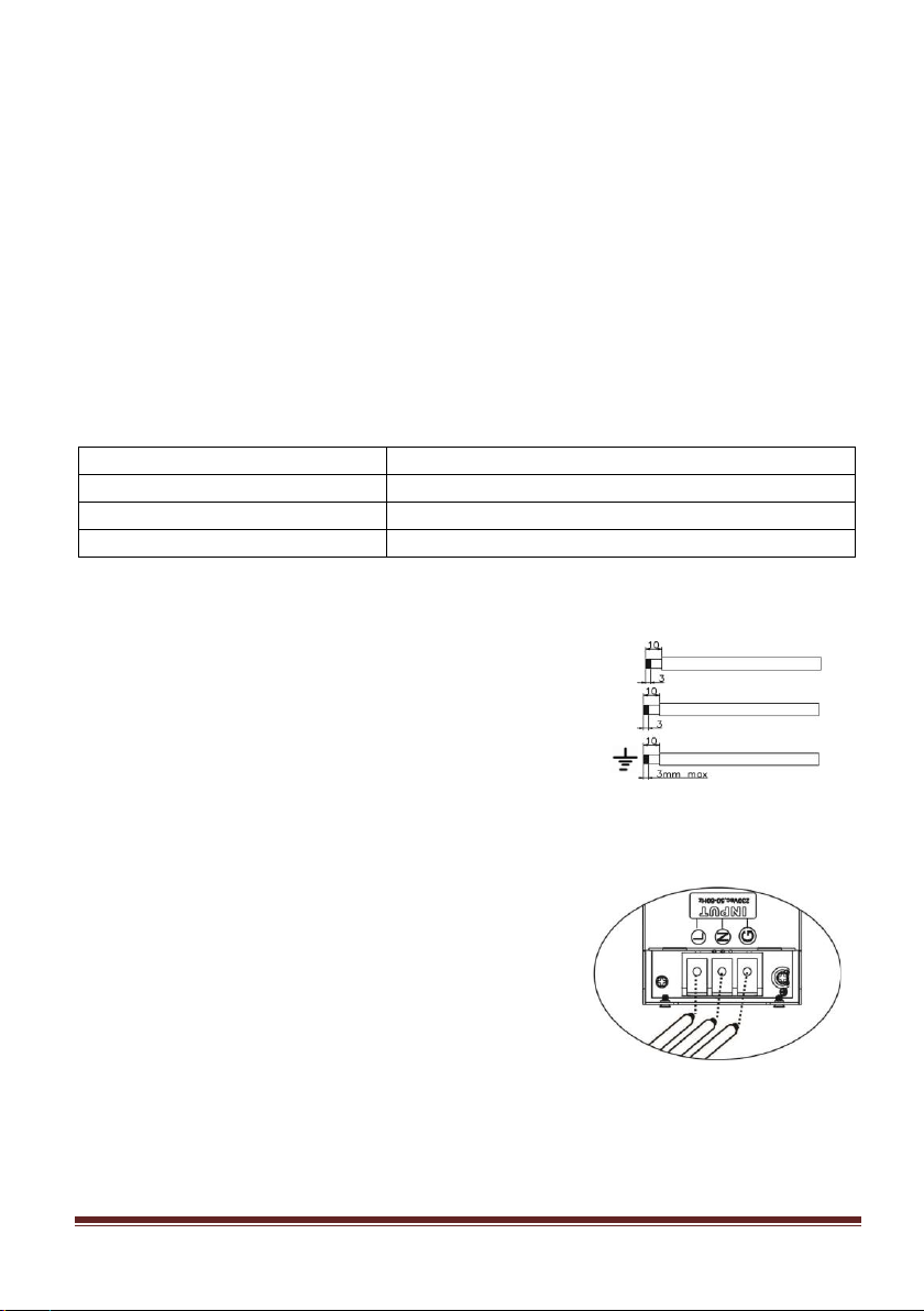
For proper operation of this inverter, please use appropriate cables for grid connection.
The pollution degree of the inverter is PD2. Select an appropriate mounting location.
Install the solar inverter in a protected area that is dry, free of excessive dust and with
adequate air flow. Do NOT operate it in the place where the temperature and humidity is
beyond the specific limits. (Please check the specs for the limitations.)
The inverter should be installed in the position where the disconnection means is easily
accessible.
This inverter is designed with IP20 protection for indoor applications only.
Regularly clean the fan filter.
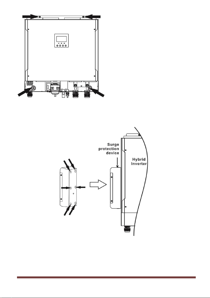
4-2. Mounting Unit
Installation to the wall should be fixed with proper screws. After that, the device should be
bolted on securely.
The inverter can only operate in a CLOSED ELECTRICAL OPERATING AREA. Only service personnel
can enter this area.
Fix the unit with four screws.
WARNING!! Remember that this inverter is heavy so please be careful when removing
it from the package.
WARNING!! FIRE HAZARD.
SUITABLE FOR MOUNTING ON CONCRETE OR OTHER NON-COMBUSTIBLE SURFACE
ONLY.

FSP HySpirit series User Manual 6
http://www.fsp-group.com.tw/en/product/PVInverter.html
5. Surge Protection Device Installation
CAUTION: Be sure to disconnect from AC power before installing surge protection device.
Step 1: Install the SPD on the left hand side of the inverter with six magnets.
Step 2: To prevent surge protection device falling apart, use supplied L-type plate and fix it to
attach surge protection device tightly to the inverter.
Magnet x 6 pieces

FSP HySpirit series User Manual 7
http://www.fsp-group.com.tw/en/product/PVInverter.html
Step 3: Connect the OUTPUT of SPD to AC grid connectors of Hybrid Inverter. The INPUT of SPD is
connected to AC utility.
Hybrid Inverter
Output of
SPD
AC Grid Input

FSP HySpirit series User Manual 8
http://www.fsp-group.com.tw/en/product/PVInverter.html
6. Grid (Utility) Connection
6-1. Preparation
Before connecting to AC utility, please install a separate AC circuit breaker between surge
protection device (SPD) and AC utility. This will ensure the inverter can be securely disconnected
during maintenance and fully protected from over current of AC input.
NOTE1: Although this inverter is equipped with 250Vac/40A fuse, it’s still necessary to install a
separate circuit breaker for safety consideration. Please use 250Vac/40A circuit breaker between
surge protection device (SPD) and AC utility.
NOTE2: The overvoltage category of the AC input is III. It should be connected to the power
distribution.
WARNING! For safety and efficiency, it's very important to use appropriate cables for grid (utility)
connection. To reduce risk of injury, please use the proper cable size recommended below.
Suggested cable requirement for AC wire
Model
5.5KW
Nominal Grid Voltage
230Vac
Conductor cross-section (mm2)
6
AWG no.
10
6-2. Connecting to the AC Utility
Step 1: Check the grid voltage and frequency with an AC voltmeter to see if it’s same as the
“Vac” value on the product label.
Step 2: Turn off the circuit breaker.
Step 3: Remove insulation sleeve 10 mm from three
conductors and shorten phase L and neutral
conductor N for 3 mm. Refer to chart 1.
Step 4: Connect wires according to the polarities indicating on terminal block. Be sure to connect
PE protective conductor (G) first.
L→LINE (brown or black)
N→Neutral (blue or white)
G→Ground (yellow-green)
Step 5: Make sure the wires are securely connected.
The reference tightening torque is 1.4~1.6N.m.
7. PV Module (DC) Connection
CAUTION: Before connecting to PV modules, please install separately DC circuit breakers
L
N
Chart 1
Chart 2

FSP HySpirit series User Manual 9
http://www.fsp-group.com.tw/en/product/PVInverter.html
between inverter and PV modules.
NOTE1: Please use 600Vdc/30A circuit breaker.
NOTE2: The overvoltage category of the PV input is II.
Please follow the steps below to implement PV module connection:
Step 1: Check the input voltage of PV array modules. The acceptable input voltage of the inverter
is 250Vdc-450Vdc (with rated load). This system is applied with two strings of PV array. Please
make sure that the maximum current load of each PV input connector is 13A.
Step 2: Disconnect the circuit breaker and switch off the DC switch.
Step 3: Assemble provided PV connectors with PV modules by the following steps.
Components for PV connectors and Tools:
Female connector housing
Female terminal
Male connector housing
Male terminal
Crimping tool and spanner
Prepare the cable and follow the connector assembly process:
Strip one cable 8 mm on both end sides and be careful NOT to nick
conductors.
Insert striped cable into female terminal and crimp female terminal as
shown below.
Insert assembled cable into female connector housing as shown below.
CAUTION: Exceeding the maximum input voltage can destroy the unit!! Check the
system before wire connection.
WARNING: Because this inverter is non-isolated, only three types of PV modules are
acceptable: single crystalline and poly crystalline with class A-rated and CIGS
modules.
To avoid any malfunction, do not connect any PV modules with possible current
leakage to the inverter. For example, grounded PV modules will cause current leakage
to the inverter. When using CIGS modules, please be sure NO grounding.
CAUTION: It’s requested to use PV junction box with surge protection. Otherwise, it
will cause damage on inverter when lightning occurs on PV modules.

FSP HySpirit series User Manual 10
http://www.fsp-group.com.tw/en/product/PVInverter.html
Insert striped cable into male terminal and crimp male terminal as shown below.
Insert assembled cable into male connector housing as shown below.
Then, use spanner to screw pressure dome tightly to female connector and male connector as
shown below.
Step 4: Check the correctness of the polarity of connection cable on PV modules and PV input
connectors. Then, connect positive pole (+) of connection cable to positive pole (+) of PV input
connector. Connect negative pole (-) of connection cable to negative pole (-) of PV input connector.
WARNING! For safety and efficiency, it's very important to use appropriate cables for PV module
connection. To reduce risk of injury, please use the proper cable size as recommended below.
Conductor cross-section (mm2)
AWG no.
4~6
10~12
CAUTION: Never directly touch the terminals of inverter. It might cause lethal electric
shock.

FSP HySpirit series User Manual 11
http://www.fsp-group.com.tw/en/product/PVInverter.html
Recommended Panel Configuration
Solar Panel Spec.
(reference)
- 260Wp
- Vmp: 30.7Vdc
- Imp: 9.18A
- Voc: 38.9Vdc
- Isc: 8.56A
- Cells: 60
SOLAR INPUT 1
SOLAR INPUT 2
Q'ty of
panels
Total Input
Power
(Min in serial: 6pcs;
Max. in serial: 12pcs)
6pcs in serial
x
6pcs
1,560W
x
6pcs in serial
6pcs
1,560W
8pcs in serial
x
8pcs
2,080W
x
8pcs in serial
8pcs
2,080W
6pcs in serial
6pcs in serial
12pcs
3,120W
7pcs in serial
7pcs in serial
14pcs
3,640W
8pcs in serial
8pcs in serial
16pcs
4,160W
10pcs in serial
10pcs in serial
20pcs
5,200W
12pcs in serial
12pcs in serial
24pcs
6,240W
8. Battery Connection
CAUTION: Before connecting to batteries, please separately install a DC circuit breaker between
inverter and batteries.
NOTE1: Please only use sealed lead acid battery, vented and Gel battery. Please check its
maximum charging voltage and current when first using this inverter. If using Lithium iron or Nicd
battery, please consult with installer for the details.
NOTE2: Please use 80Vdc/200A circuit breaker.
NOTE3: The overvoltage category of the battery input is II.
Please follow the steps below to implement battery connection:
Step 1: Check the nominal voltage of batteries. The nominal input
voltage for inverter is 48Vdc.
Step 2: Use two battery cables. Remove insulation sleeve 12 mm and
insert conductor into cable ring terminal. Refer to the right diagram.
Step 3: Remove the cover of battery and follow the polarity of battery printed near the battery
terminal! Place the external battery cable ring terminal over the battery terminal.
RED cable to the positive terminal (+);
BLACK cable to the negative terminal (-).
CAUTION: Do NOT touch the inverter to avoid electric shock. When PV modules are
exposed to sunlight, it may generate DC voltage in the inverter.

FSP HySpirit series User Manual 12
http://www.fsp-group.com.tw/en/product/PVInverter.html
WARNING! Wrong connections may damage the unit permanently.
Step 4: Make sure the wires are securely connected. The reference tightening torque is 2.04 N.m.
WARNING! For safety and efficiency, it's very important to use appropriate cables for battery
connection. To reduce risk of injury, please use the proper cable size recommended as below.
Conductor cross-section (mm2)
38
AWG no.
2
9. Load (AC Output) Connection
CAUTION: To prevent extra supply to the load via the inverter during any mode of operation, an
additional disconnection device should be placed on in the building wiring installation.
WARNING! For safety and efficiency, it's very important to use appropriate cable for AC
connection. To reduce risk of injury, please use the proper cable size recommended as below.
Model
5.5KW
Nominal Grid Voltage
230Vac
Conductor cross-section (mm2)
6
AWG no.
10
Step 1: Remove insulation sleeve 8 mm for three conductors. And shorten phase L and neutral
conductor N 3 mm. Refer to Diagram 3.
Step 2: Connect wires according to the polarities indicated on
terminal block. Be sure to connect PE
protective conductor ( ) first. Refer to Diagram 4.
L
N
Diagram 3

FSP HySpirit series User Manual 13
http://www.fsp-group.com.tw/en/product/PVInverter.html
L→LINE (brown or black)
→Ground (yellow-green)
N→Neutral (blue or white)
Step 3: Make sure the wires are securely connected. The
reference tightening torque is 1.4~1.6N.m.
CAUTION: It’s only allowed to connect load to “AC Output Connector”. Do NOT connect
the utility to “AC Output Connector”.
CAUTION: Be sure to connect L terminal of load to L terminal of “AC Output Connector”
and N terminal of load to N terminal of “AC Output Connector”. The G terminal of “AC
Output Connector” is connected to grounding of the load. Do NOT mis-connect.
CAUTION: This inverter is not allowed to operate in parallel. Please do NOT connect
more than one unit in parallel in AC output connector. Otherwise, it will damage this
inverter.
Diagram 4

FSP HySpirit series User Manual 14
http://www.fsp-group.com.tw/en/product/PVInverter.html
10. Communication
The inverter is equipped with RS232 port, USB port and a slot for alternative communication
interfaces in order to communicate with a PC via corresponding software. This intelligent
slot is suitable to install with SNMP card and Modbus card. Follow the procedure below to
connect communication wiring and install the software.
For RS232 port, you should use a DB9 cable as below:
For USB port, you should use a USB cable as below:
For SNMP or MODBUS card, you should use RJ45 cables as below:
Please install monitoring software in your computer. Detailed information is listed in next
chapter. After software is installed, you may initialize the monitoring software and extract
data through communication port.

FSP HySpirit series User Manual 15
http://www.fsp-group.com.tw/en/product/PVInverter.html
11. Application with Energy Meter
With Modbus card II and energy meter, hybrid inverter can be easily integrated into the existing
household system. For details please refer to Modbus card II manual.
Note: This application is only valid for Grid-Tie with Backup II mode.
Equipped with Modbus card II, hybrid inverter is connected to energy meter with RS485
communication port. It’s used to set up self-consumption function via Modbus card to control
power generation and battery charging of the inverter.
Hybrid Inverter
Battery
To Main
Family Load
RS-485
EnergyMeter
Grid
L1
L2
L3
N
L
Grid
Modbus card
AC Output
PV Arry
N
G
L
N
G
To Urgent
Load

FSP HySpirit series User Manual 16
http://www.fsp-group.com.tw/en/product/PVInverter.html
12. Commissioning
Step 1: Check the following requirements before commissioning:
Ensure the inverter is firmly secured
Check if the open circuit DC voltage of PV module meets the requirement (Refer to Section
6)
Check if the voltage of the open circuit utility is approximately as same as the expected
nominal value from local utility company.
Check if connection of AC cable to grid (utility) is correct if the utility is required.
Fully connect to PV modules.
Check if AC circuit breaker (only applied when the utility is required), batter circuit breaker,
and DC circuit breaker are installed correctly.
Step 2: Switch on the circuit breaker of battery and then switch on PV DC breaker. After that, if
there is any connection with utility, please switch on the AC circuit breaker. At this moment, the
inverter is already turned on. However, there is no output generation from loads. Then:
If LCD lights up to display the status of current inverter, commissioning has been completed
successfully. After pressing “ON” button for 1 second when the utility is detected, this
inverter will start to supply power to the loads. If no utility exists, simply press “ON” button
for 3 seconds. Then, this inverter will start to supply power to the loads.
If an error occurs to this inverter, a warning/fault indicator will appear on LCD display. Please
inform your installer.
Step 3: Please insert CD into your computer and install monitoring software on your PC. Follow
the steps below to install the software.
1. Follow the on-screen instructions to install the software.
2. When your computer restarts, the monitoring software will appear as shortcut icon located in
the system tray, near the clock.
NOTE: If using modbus card as communication interface, please install bundled software. Check
local dealer for the details.

FSP HySpirit series User Manual 17
http://www.fsp-group.com.tw/en/product/PVInverter.html
13. Initial Setup
Before inverter starts to operate, it’s required to set up “Operation Mode” via software. Please
strictly follow the steps below to set up. For more details, please refer to software manual.
Step 1: After turning on the inverter and installing the software, please click “Open Monitor” to
enter main screen of this software.
Step 2: Log in the software first by entering the default password “administrator.”
Step 3: Select Device Control>>MyPower Management to set up inverter operation mode and
personalized interface. Refer to diagram below.
Mode
There are three operation modes: Grid-tie with backup, Grid-Tie and Off-Grid.
Grid-tie with backup: PV power can feed back to grid, provide power to the load and charge
battery. There are four options available in this mode: Grid-tie with backup I, II, III and IV. In
this mode, users can configure PV power supply priority, charging source priority and load
supply source priority. However, when Grid-tie with backup IV option is selected in PV energy
supply priority, the inverter is only operating between two working logics based on defined
peak time and off-peak time of electricity. Only peak time and off-peak time of electricity are
able to set up to optimize electricity usage.
Grid-Tie: PV power can only feed back to grid.
Off-Grid: PV power can only provide power to the load and charge battery but can’t feed
back to grid.
SECTION A:
Standard: It will list local grid standard. To make any modification, you’re requested to have
factory password. Please check local dealer only when this standard change is requested.
CAUTION: Wrong setting could cause damage to the unit or not working.

FSP HySpirit series User Manual 18
http://www.fsp-group.com.tw/en/product/PVInverter.html
Nominal Output Voltage: 230V.
Nominal Output Frequency: 50HZ.
SECTION B:
This section contents may be different based on different selection of operations.
Allow AC charging duration: It’s a period of time to allow AC (grid) to charge battery. When the
duration is set as 0:00-00:00, it means no time limitation for AC to charge battery.
AC output ON/Off Timer: Set up on/off time for AC output of inverter. If setting it as 00:00/00:00,
this function is disabled.
Allow to charge battery: This option is automatically determined by setting in “Charging source”.
It’s not allowed to modify here. When “NONE” is selected in charging source section, this option
becomes unchecked in grey text.
Allow AC to charge battery: This option is automatically determined by setting in ”Charging source”.
It’s not allowed to modify here. When “Grid and PV” or “Grid or PV” is selected in charging source
section, this option is default selected. In Grid-tie mode, this option is invalid.
Allow to feed-in to the Grid: This option is only valid under Grid-tie and Grid-tie with backup modes.
Users can decide if this inverter can feed-in to the grid.
Allow battery to discharge when PV is available: This option is automatically determined by setting
in “Load supply source (PV is available)”. When “Battery” is higher in priority than “Grid” in Load
supply source (PV is available), this option is selected in default. Under Grid-tie, this option is
invalid.
Allow battery to discharge when PV is unavailable: This option is automatically determined by
setting in “Load supply source (PV is unavailable)”. When “Battery” is higher in priority than “Grid”
in Load supply source (PV is unavailable), this option is selected in default. In Grid-tie mode, this
option is invalid.
Allow battery to feed-in to the Grid when PV is available: This option is only valid in Grid-tie with
backup II or Grid-tie with backup III modes.
This manual suits for next models
1
Table of contents
Other FSP Technology Inverter manuals
Popular Inverter manuals by other brands

RIPEnergy
RIPEnergy Swing Pro 200VA user manual

Vector
Vector MAXX SST VEC051D Owner's manual & warranty information

Black & Decker
Black & Decker BDPC400AU instruction manual

Dukane
Dukane AiM Application note

Growatt
Growatt Grid Installation & operation manual

solarwatt
solarwatt MYRESERVE installation instructions