FSR DV-HMSW4K-44 User manual

2
SURGE PROTECTION DEVICE RECOMMENDED
This product contains sensitive electrical components that may be damaged by
electrical spikes, surges, electric shock, lightning strikes, etc. Use of surge
protection systems is highly recommended in order to protect and extend the
life of your equipment.
POWER SUPPLY VOLTAGE WARNING
This unit is equipped with a 5 volt power supply. Use only the correct, center
positive 5 volt supply or damage to the unit itself and any connected equipment
may result. Damage caused by incorrect power supply voltage or polarity is not
covered under the warranty.

3
Table of Contents
Features ...........................................................................................................................................4
What’s in the box..............................................................................................................................4
Specifications ...................................................................................................................................5
Panel Descriptions ...........................................................................................................................6
Connecting and Operating...............................................................................................................7
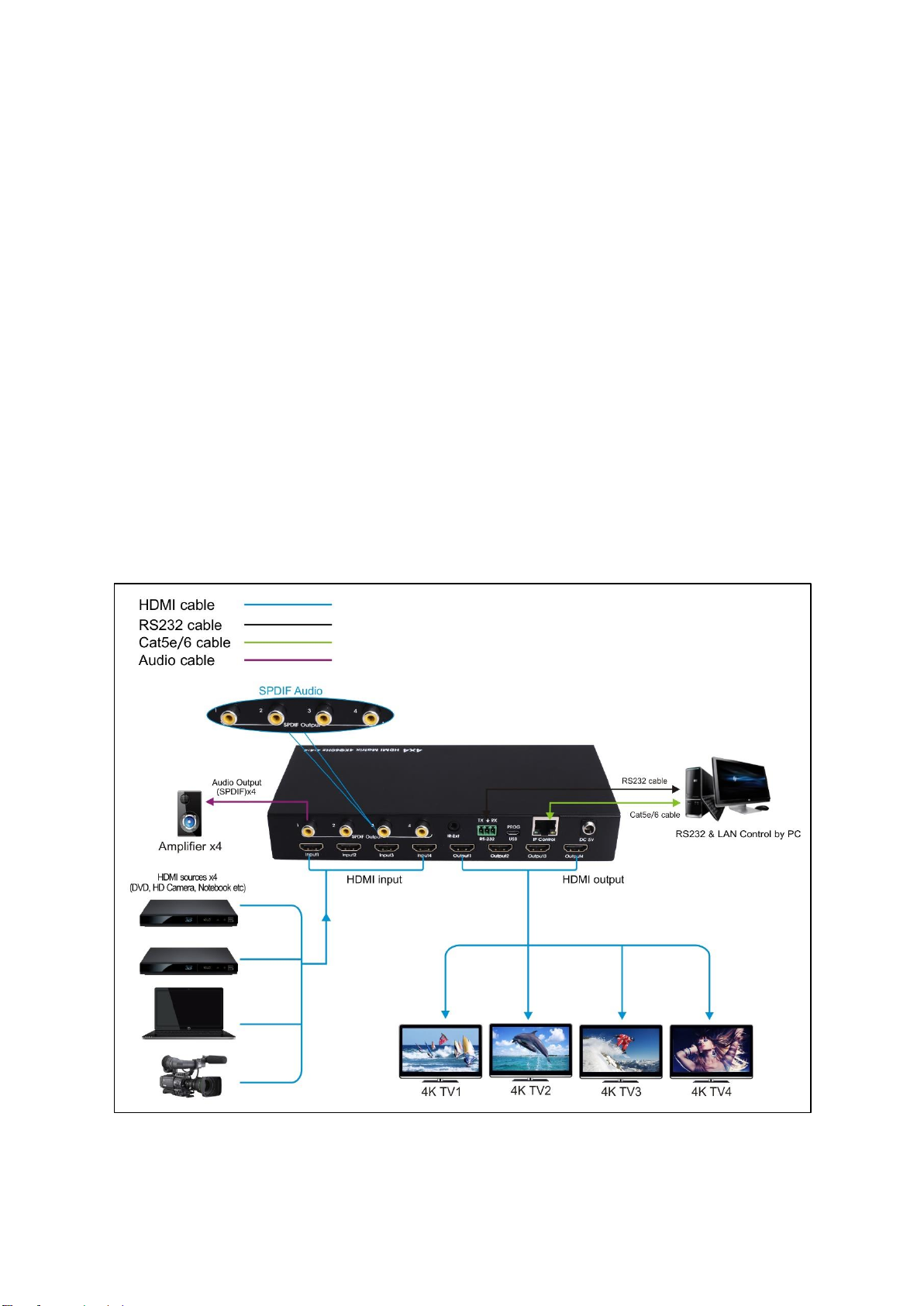
Application Diagram.........................................................................................................................7
Remote Control Description.............................................................................................................8
RS232 Pin Assignment ....................................................................................................................8
RS232 Control..................................................................................................................................9
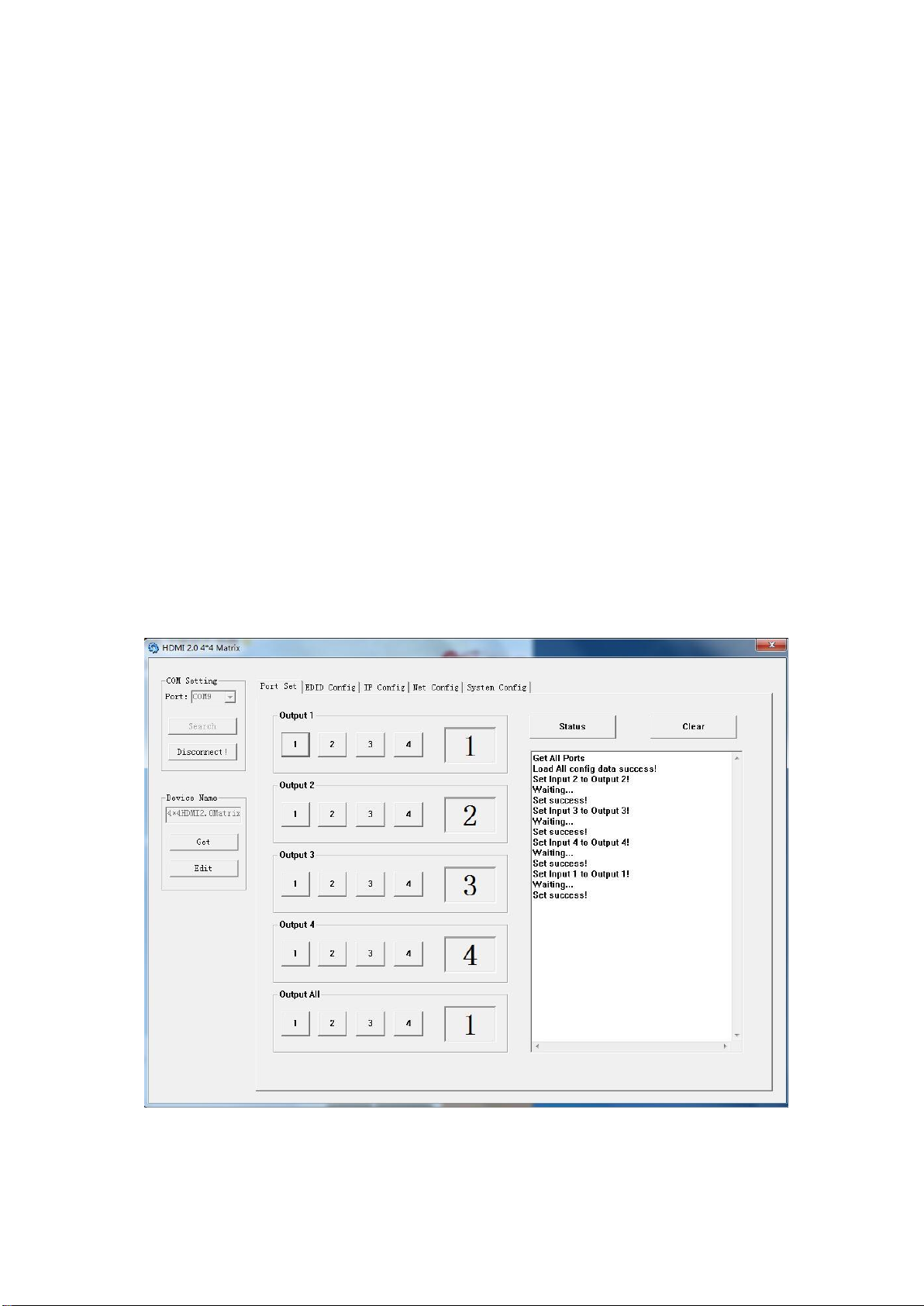
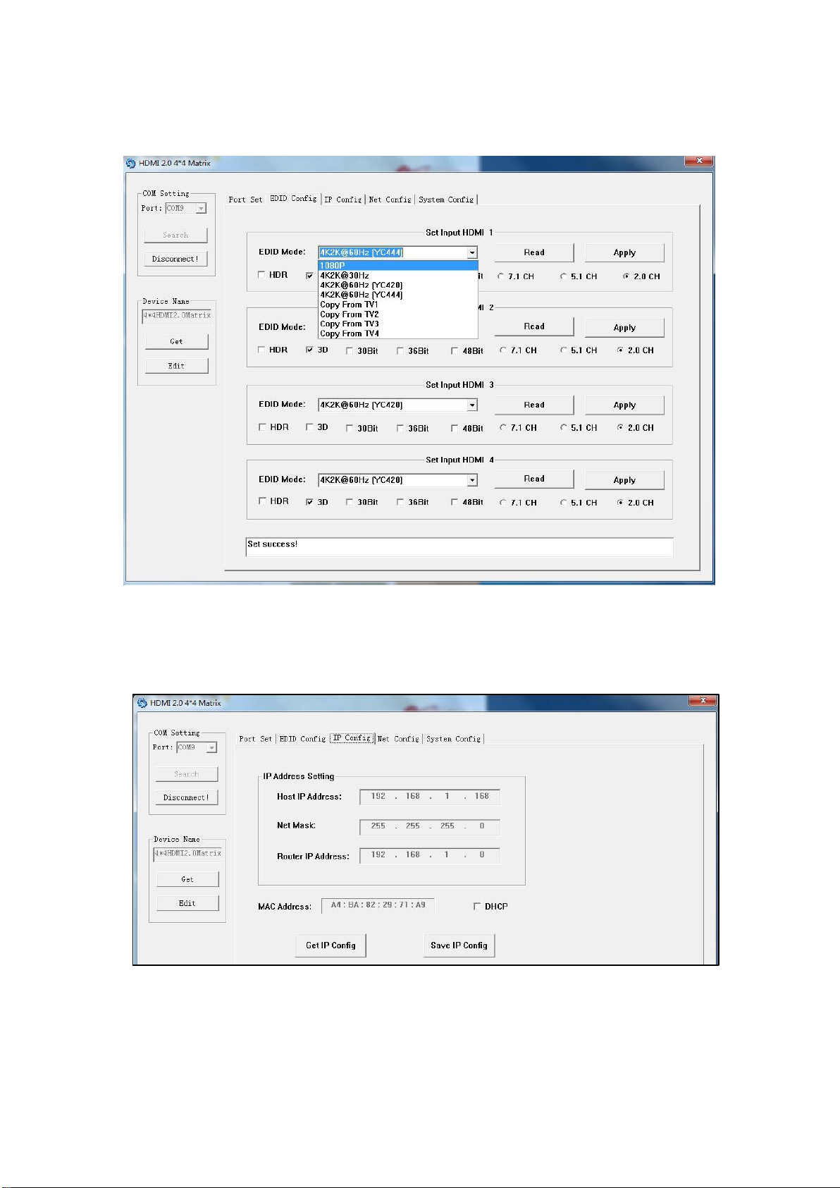
Web GUI Control............................................................................................................................17
Controlling the Matrix via the WEB GUI ........................................................................................19
Online upgrading firmware.............................................................................................................22
Limited Warranty ............................................................................................................................23

4
Features
HDMI 2.0 and HDCP 2.2 compliant device supports up to 4K @60Hz YUV 4:4:4 HDR
Bandwidth up to 18Gbps
HDR supports high dynamic range 10bit (HDR10)
HDCP2.2 input ,HDCP2.2 output
HDCP1.4 input, HDCP1.4 output
4xHDMI Input, 4xHDMI output with 4xSPDIF Audio
Any one of the 4 Ultra HD sources to any one of the 4 Ultra HD displays
Supports Panel Button, Local IR, RS232 Control with command, IP Control, Web GUI Control
Supports Dolby True HD and DTS-HD master audio, Dolby Atmos under copy EDID mode
Supports firmware updating through USB port
Unit size: 8.5”W x 4.2”D x 1.38”H (Not including connectors)
What’s in the box
1x HDMI Matrix
1x 5V DC power supply** See Caution on page 2
1x Remote control
1x IR Ext RX Cable
1x Phoenix plugs for RS232 cable termination
1x mounting kit
1x CD for control software & user manual

5
Specifications
Operating Temperature
23°F to 113°F (-5°C to 45°C)
Storage Temperature
-4°F to 140°F (-20°C to 60°C)
Resolution
480p@60hz,576P@50hz,720P@60hz,
1080P@24hz,1080P@50hz,1080P@60hz,4K@24hz,4K@3
0hz,
4K@60hz YUV4:2:0, 4K@ 60hz YUV4:4:4 HDR (HDR10)
HDCP Compliant
HDCP2.2 and HDCP1.4
Output Video
HDMI2.0 and HDMI 1.4
Audio Format Supported
PCM, Dolby5.1/7.1, DTS5.1/7.1 digital audio, Dolby Atmos
RS-232 serial port
3PIN terminal block connectors
Ethernet port (IP control)
RJ45, female
IR Ext port
1x3.5mm stereo jack
USB port
Micro 5P female
Bandwidth
18 Gbps
Default IP
192.168.1.168
Rack-Mountable
Rack ears included
Chassis dimensions(WxHxD)
8.5”W x 4.2”D x 1.38”H (Not including connectors)
Shipping dimensions (carton):
10”W x 8”D x 1.5”H
Shipping weight
2.35 lbs. / 1.06 kg
Power consumption
13W (Max)

6
Panel Descriptions
①IR receive window.
②Output button OUT1~4: choose the desired output port from input ports 1~4.
Note: 1) Turn on/off DHCP function: press the selector of output 1 and output 2
for 3 seconds.
2) Restore factory settings: when all outputs select input 1, press the
selector of output 3 and output 4 for 3 seconds.
①SPDIF Audio outputs.
②For IR external receiver cable.
③RS232 for control or upgrading the firmware.
④USB micro 5P port for upgrading the firmware.
⑤IP control.
⑥DC power inputs.
⑦HDMI input ports.
⑧HDMI output ports.

7
Connecting and Operating
1. Connect source devices to input ports of the matrix
2. Connect HDMI output ports to TV or other HDMI display devices.
3. Optional: connect RS232 cable from PC RS232 port.
4. Optional: connect an Ethernet cable from the TCP/IP port on the matrix to alocal area
network.
5. Connect 5V POWER supply to DC power jack. See Caution on page 2.
6. Power on the matrix, HDMI sources and displays.
Application Diagram

8
Remote Control Description
① Standby Mode button
② OUTPUT-x select INPUT-y:
Press OUTPUT-x (x means 1 to 4 of outputs) Press
INPUT-Y (y means 1 to 4 of inputs)
③ All outputs button select INPUT-y:
Press ALL button in zone OUTPUT
Press INPUT-Y button (y means 1 to 4 of inputs),
then INPUT-y switched to ALL OUTPUTS.
④ Cancel Button: Cancel the switching operation
⑤PTP button: Mirror all inputs and outputs
(Ex. Input 1 to output 1, input 2 to output 2, etc): Press
PTP button in Zone OUTPUT
RS232 Pin Assignment
Matrix
Remote Control Console
Assignment
PIN
Assignment
1
NC
Tx
2
Rx
Rx
3
Tx
4
NC
GND
5
GND
6
NC
7
NC
8
NC
9
NC

9
RS232 Control
Software control
Connect the 4x4 Matrix to PC with a RS232 cable and open the DV-HMSW4K-44 Remote
application available on the FSR website (www.fsrinc.com). In the COM Setting window, select the
COM port according to your PC and click Connect to connect to the unit.
The Port Set tab on the application monitors and allows control of the routing configuration of the
matrix. Select the desired input button on individual output channels or route a selected input
globally to all outputs by pressing the appropriate button. The currently selected input is displayed
to the right of each output window. The com status window provides information on the success or
failure of communication with the unit and can be cleared by pressing the clear button. The status
button can be pressed to poll the unit for its current status in case routing changes were made
while there was no serial connection.
You can change the default device name by selecting “Edit” and typing in the Device Name window.
Click “SaveLock” when done. The Device Name may be up to 16 characters in length.
Picture 1: Porting Setting

10
The EDID tab is used to Read and Configure EDID for each input, such as HDR, 3D, Data rates
and Audio channel.
Picture 2: EDID Setting
The IP configure tab is used to read and configure the IP address and MAC of the Matrix. Click
DHCP if you want the router to assign an automatic IP for the Matrix.
Picture 3: IP Config
The Net Config tab allows users to configure the PC and Matrix in the same LAN with the IP
Address and connection.

11
Click “Net config” → “Connect” →“Search Device”→“Sel Device Number”→“Connect” to see the
device name. This indicates a successful connection.
Picture 4: Net Config
You can also click “IE” and click to enter into web.
Picture 5: Net Config

12
The last tab is System Config, which allows power ON/OFF or reset, default the Matrix.
Picture 6: System config
Command Control
1). Open CommUart Assistant.
2). Comport setting:
Baud Rate:
115200 bps
Parity:
None
Data Bits:
8 bit
Stop Bits:
1 bit
3). Enter Port Command in Send options.
Picture 7
NOTE:
Serial over Ethernet setting is IP port: 5000

13
Note: All commands and responses are in ASCII. Commands and are white space
insensitive and are terminated with #.
4). General Commands:
Command
Function
Note
@W 04 00 01 02 03 #
PTP Function
Allows all outputs to be switched to the specified
inputs in a single command.
(Ex. Input 1 to output 1, input 2 to output 2, etc)
@W 50 #
Reboot
Reboot matrix
@W 51 #
Restore Factory Setting
Restore unit to factory clearing any user settings
@W 0F 00 #
Standby
00: Standby Mode
01: Cancel “Standby Mode”
5). PTP command:
Format: @W 04 O1 O2 O3 O4 #
Parameter Description:
O1 = Input number (0-3) to route to output 1
O2 = Input number (0-3) to route to output 2
O3 = Input number (0-3) to route to output 3
O4 = Input number (0-3) to route to output 4
Example: @W 04 02 02 01 00 #
Route input 3 to outputs 1 and 2, input 2 to output 3, and input 1 to output 4
6). Output Routing Command:
Format: @W OO II #
Parameter Description:
OO = Output Number as indicated below:
II = Input Number as indicated below:
Command
Description
00
Output1
01
Output2
02
Output3
03
Output4
04
All Output
00
Input1
01
Input2
02
Input3
03
Input4
Example: @W 00 03 #
Output 1 comes from Input 4

14
7). EDID Setting Command:
Format: @W II AA BB #:
Parameter Description:
II = Input Number to configure
Value
05
06
07
08
Input #
Input1
Input2
Input3
Input4
AA = EDID File to use as indicated below
00= 1080P
01= 4K2K_30
02=4K2K_60(YC420)
03=4K2K_60(YC444)
04=Copy from display 1
05=Copy from display 2
06=Copy from display 3
07=Copy from display 4
BB = EDID file parameters as shown in chart below:
Bit7
Bit6
Bit5
Bit4
Bit3
Bit2
Bit1
Bit0
HDR
48Bit
36Bit
30Bit
7.1CH
5.1CH
2CH
3D
1
1
1
1
1
1
1
1
0
0
0
0
0
0
0
0
“1” = enable the function, “0” = disable the
function.
For example: 11001001: HDR, 48Bit, 7.1CH, 3D
Convert Binary code “11001001” to hexadecimal format “C9”.
Example: @W 05 03 C9 # (Note: All characters shown are in ASCII; “C9” = 43, 39)
The EDID file setting of input 1 indicates: 4K2K_60(YC444)、HDR、48Bit、7.1CH、3D.
Note: This field has invalid and has no effect for any “copy from display” EDID settings

15
8). Matrix Status Inquiry:
Format: @R YY #:
Parameter Description:
YY = Output/Input to query as indicated below:
YY
Description
30
Output1
31
Output2
32
Output3
33
Output4
34
All Output
35
Input Status
Unit responds with:
@R YY II AA BB #:
Parameter Description:
YY = status being reported:
Command
30
31
32
33
34
35
Description
Output1
Output2
Output3
Output4
All Outputs
Input Status
II = Input # ( 00 = input1…03 = input4)
Command
00
01
02
03
Description
Input1
Input2
Input3
Input4
AA Indicates Input EDID setting:
00= 1080P
01= 4K2K_30
02=4K2K_60(YC420)
03=4K2K_60(YC444)
04=Copy from display 1
05=Copy from display 2
06=Copy from display 3
07=Copy from display 4
BB indicates Input EDID video/audio mode (valid only for AA=00, 01, 02, 03, I imagine)
Bit7
Bit6
Bit5
Bit4
Bit3
Bit2
Bit1
Bit0
HDR
48Bit
36Bit
30Bit
7.1CH
5.1CH
2CH
3D
1
1
1
1
1
1
1
1
0
0
0
0
0
0
0
0
“1”: function is enabled, “0”: function is disabled, “XX”; invalid

16
Example Status Request:
@R 30 #: (Get Status of Output 1)
Response: @R 30 01 04 XX #
Output 1 is connected to input2, Input2 EDID is set to “copy from display 1”, EDID video/audio data
is not valid.
AA = Selected EDID file as defined in EDID setting command above
BB = EDID file parameters as defined in EDID setting command above
Note: All “copy from display” EDID settings return XX (invalid) for this parameter
Example 1: @R 34 #: (Get Status of All Outputs)
Response:
@R 30 00 04 XX #
@R 31 01 00 C9 #
@R 32 02 01 C9 #
@R 33 03 04 XX #
Output 1 is connected to input1, Input1 EDID is set to “copy from display 1”, EDID video/audio
data is not valid.
Output 2 is connected to input2, Input2 EDID is set to “1080P”, EDID video/audio data indicates
HDR, 48bit, 7.1CH, 3D
Output 3 is connected to input3, Input3 EDID is set to “4K2K_30”, EDID video/audio data indicates
HDR, 48bit, 7.1CH, 3D
Output 4 is connected to input4, Input4 EDID is set to “copy from display 1”, EDID video/audio
data is not valid.
Example 2: @R 35 #: (Get All Input Status)
Response: @R 35 CC #:
CC = input channel signal status (HDMI and +5V present (cable connected to source)) as
described below:
“1” signal is present, “0” signal is not present
Example Input Status Request:
@R 35 #:
Response:
@R 35 CE #
HDMI signal present on inputs 4 and 3, +5 volts present on pin 18 of inputs 4, 3, and 2.
Bit7
Bit6
Bit5
Bit4
Bit3
Bit2
Bit1
Bit0
In 4 HDMI
In 3 HDMI
In 2 HDMI
In 1 HDMI
Input 4 +5V
Input 3 +5V
Input 2
+5V
In 1 +5V
1
1
1
1
1
1
1
1
0
0
0
0
0
0
0
0

17
Web GUI Control
Static IP Address:
The default IP Address of HDMI Matrix is 192.168.1.168.
Change the IP address of your PC.
. Connect the HDMI Matrix and PC to the LAN.
. Configure your PC as follows:
Click Start > Control Panel > Network and Sharing Center.
Click Change Adapter Settings.
Highlight the network adapter you want to use to connect to the device and click
Change settings of this connection.
. Connect to the device and click change settings of this connection:
Picture 8

18
. Highlight Internet Protocol Version 4 (TCP/IPv4) by clicking on the item.
. Click Properties.
Picture 9
1). Select Use the following IP Address for static IP addressing and fill in the details.
For TCP/IPv4 you can use any IP address in the range 192.168.1.2 to 192.168.1.254 (excluding
192.168.1.168).
Picture 10
2). Click OK.
3). Click Close.

19
Controlling the Matrix via the WEB GUI
Open the Web browser and enter the IP address of the HDMI Matrix:192.168.1.168,
then you can set the function as shown below:
Picture 11: Port Setting Page
Picture 12: EDID Setting Page

20
Picture 13: IP Configuration Page
DHCP
You can also choose “DHCP” for HDMI Matrix (refer to 9.1 picture3)
1). Connect the HDMI Matrix and PC to the LAN.
2). Open the PC tool (included in the CD).
3). Search the IP address of HDMI Matrix, please refer to 9.1 picture 4 & picture 5.
4). Open the web browser and enter the IP address you searched, then you can set the function
as below pictures:
Picture 14: Port Setting Page
Table of contents
Other FSR Matrix Switcher manuals