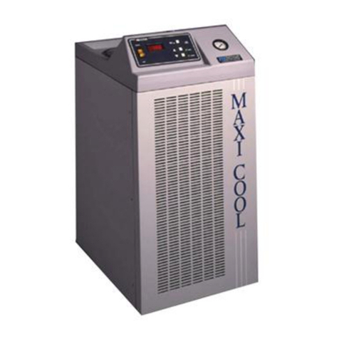
FTS RS Series User manual

Document #MNL-008-A, Rev. 009
RSSeriesChillers
Operator’sManual
FTS
3538 Main Street
Stone Ridge, NY 12484 USA
www.SPIndustries.com
(800) 824-0400 or 001 (845) 687-0071
SP Service:
(877) 548-4666 or 001 (645) 687-5400
FAX: (845) 687-0024

© SP Industries, Inc. MNL-008-A Rev. 009
ii
Notice
This Operation Manual contains confidential and proprietary information of SP Industries, Inc.
and may be used only by a recipient designated by and for purposes specified by SP
Industries, Inc.
Reproduction of, dissemination of, modifications to, or the creation of derivative works from
this manual, by any means and in any form or manner, is expressly prohibited, except with
the prior written permission of SP Industries, Inc. Permitted copies of this document must
retain all proprietary notices contained in the original.
The information in this document is subject to change without prior notice. Always confirm
with SP Industries, Inc. that you are using the most current version of this document. SP
Industries, Inc. is free to modify any of its products and services, in any manner and at any
time, notwithstanding the information contained in this document.
THE CONTENTS OF THIS DOCUMENT SHALL NOT CONSTITUTE ANY WARRANTY OF
ANY KIND, EITHER EXPRESSED OR IMPLIED, INCLUDING BUT NOT LIMITED TO THE
IMPLIED WARRANTIES OF MERCHANTABILITY AND/OR FITNESS FOR A PARTICULAR
PURPOSE OR GIVE RISE TO ANY LIABILITY OF SP INDUSTRIES, INC., ITS AFFILIATES
OR ITS SUPPLIERS.
The terms and conditions governing the use of this Operation Manual shall consist of those
set forth in written agreements with SP Industries, Inc.
All brand or product names mentioned may be trademarks or registered trademarks of their respective companies.
© 2007 SP Industries, Inc. All marks herein are used under license.

© SP Industries, Inc. MNL-008-A Rev. 009
iii
Contents
Contents........................................................................................................................................ iii
Important Symbols........................................................................................................................ 4
Foreword ........................................................................................................................................ 5
Safety Precautions...................................................................................................................................... 5
Inspection ................................................................................................................................................... 6
Introduction.................................................................................................................................... 7
Model Number Identification .................................................................................................................... 7
Installation...................................................................................................................................... 8
Physical Location..................................................................................................................................... 8
Ambient Air Requirements ....................................................................................................................... 8
Selecting a Process Fluid ........................................................................................................................... 9
Process Fluid Properties.........................................................................................................................10
Electrical Requirements.............................................................................................................................11
High pressure Bypass Hook-Up (Accessory).............................................................................................12
Connect to the Process .............................................................................................................................13
Operation...................................................................................................................................... 14
User Menu .................................................................................................................................... 16
User Menu Layout .....................................................................................................................................17
Proportional Control Menu.........................................................................................................................18
Span Menu ................................................................................................................................................19
Miscellaneous Menu ..................................................................................................................................20
Communications Menu ..............................................................................................................................21
High Fluid Temperature .............................................................................................................................22
Low Fluid Temperature..............................................................................................................................23
PID Tuning.................................................................................................................................................24
IT and DT...................................................................................................................................................25
CCT ...........................................................................................................................................................25
CPB ...........................................................................................................................................................26
HPB, CPB, AND DB ..................................................................................................................................27
RS-232 Communications Programmer's Reference ................................................................ 28
Maintenance................................................................................................................................. 42
Troubleshooting .......................................................................................................................... 47
Service.......................................................................................................................................... 50
FTS Warranties and Service Agreements .................................................................................................50
Standard Warranty.....................................................................................................................................51
Service Options .........................................................................................................................................52
Extended Warranty: ................................................................................................................................52
Preventative Maintenance: .....................................................................................................................52
Service Contract: ....................................................................................................................................52
Return of FTS Equipment ..........................................................................................................................53

© SP Industries, Inc. MNL-008-A Rev. 009
4
ImportantSymbols
FTS designs and manufactures units to be safe and reliable systems. Safety features are
incorporated throughout and appropriate signs and symbols are provided. In this manual,
safety issues are addressed in context. Users are strongly encouraged to become familiar
with these symbols.
Warning! Refer to manual text. Injury or even death
may result if a recommendation marked with this symbol
is not heeded.
Electric Shock Danger! Use appropriate caution to avoid injury or death.
Burn Danger! Potentially hot surface. Use appropriate caution.
Do not store flammable materials in chamber.
Wear Safety Glasses.
Crush Hazard. Keep hands clear when operating door.
Corrosive Chemical. Wear suitable gloves, safety glasses, and protective
clothing.
Property Caution! To prevent damage to chamber equipment and/or load,
adhere to procedures marked by this symbol.
Practical Operating Tip. These recommendations streamline unit operation and
prevent common operator errors.

© SP Industries, Inc. MNL-008-A Rev. 009
5
Foreword
Thank you for buying an SP Industries / FTS product. Our goal is 100 percent customer
satisfaction. If you are in any way dissatisfied with your order, please contact us immediately.
Safety Precautions
Your satisfaction and safety will be assured by a complete understanding of this equipment.
To assure your satisfaction and safety, as end user of this equipment, it is the operator’s
responsibility to understand its function and operational characteristics. Before operating this
equipment please read this instruction manual thoroughly. Ensure that all operators receive
appropriate training.
Awareness of the stated cautions and warnings, compliance with recommended operating
parameters, and performance of periodic maintenance requirements are important for safe
and satisfactory operation.
Your instruction and maintenance manual is valuable as it contains information to help you
better understand and operate the equipment you have purchased. It includes a wiring
diagram and contact numbers, which you may require at some future date. Keep it close at
hand and refer to it often. Additional manuals may be purchased from our Parts Department.
If any part of these instructions is not clearly understood, please feel free to contact Customer
Service for clarification.
If you require replacement parts, we must have the model and serial numbers plus all
electrical information from the nameplate.
The unit should be used for its intended application; alterations or modifications will void the
warranty. This product is not intended, nor can it be used, as a sterile or patient-connected
device, nor is it designed for use in Class I, II, or III locations as defined by the National
Electrical Code.
Never use with toxic, corrosive, flammable or organic materials unless special precautions
are in place to prevent injury to personnel or damage to equipment.
Never operate unit without all covers in place.
Never clean with solvents. Use mild detergent and water only.
Never allow hands or body to be exposed to open vacuum ports.
Always verify that the electric service and other utilities match the unit’s requirements before
connecting to power.
WARNING! FOLLOW THESE INSTRUCTIONS TO AVOID INJURY AND/OR DAMAGE TO EQUIPMENT.
CAUTION
As a routine safety precaution, always wear safety glasses when working
with this equipment.

Operator’s Manual: RS Series Chiller Foreword
© SP Industries, Inc. MNL-008-A Rev. 009
6
Always wear safety glasses when using glass flasks.
Always practice team lifting when moving heavy equipment.
Always ensure that refrigeration air intake is clear and clean.
Always ensure that only an authorized technician services the refrigeration, heat transfer,
vacuum and electrical systems.
Always assume that internal parts may be very cold or very hot. Utilize personal protective
equipment to avoid burns.
Inspection
This merchandise was carefully packed and thoroughly inspected before leaving our factory.
Save all packing material if apparatus is received damaged.
Responsibility for its safe delivery is assumed by the carrier upon acceptance of the
shipment, therefore, claims for loss or damage sustained in transit must be made upon the
carrier by recipient as follows:
Visible loss or damage
Note any external evidence of loss or damage on the freight bill, or express receipt, and have
it signed by the carrier's agent. Failure to adequately describe any such external evidence of
loss or damage may result in carrier's refusing to honor your damage claim. The form
required to file such a claim will be supplied by the carrier.
Concealed loss or damage
Concealed loss or damage means loss or damage which does not become apparent until the
merchandise has been unpacked and inspected. Should either be discovered, make a written
request for inspection by the carrier's agent with 15 days of the delivery date; then file a claim
with the carrier since the damage is the carrier's responsibility. By following these instructions
carefully, we guarantee our full support of your claim to be compensated for loss from
concealed damage.
Do not -- for any reason -- return this unit without first obtaining authorization. Please
supply nameplate data, including model number and serial number, in any
correspondence to the manufacturer.
WARNING
DO NOT STORE OR PROCESS FLAMMABLE MATERIALS
This unit is not designed (nor is it intended to be used) for the
purpose of processing or storage of materials that may
contain volatile flammable solvents or that may emit
flammable vapors during processing or storage.

C
hapter
1
© SP Industries, Inc. MNL-008-A Rev. 009
7
Introduction
Model Number Identification
RS33 Recirculator, 1/3HP
A 120V / 60Hz
D 220V / 50Hz
0 -10°C Low Temp
L -40°C Low Temp
0 No Heater
1 600W Heater (+75°C High Temp)
02GPM,4psi
1 1.6GPM, up to 100°C
RS44 Recirculator, 1/3HP
B 230V / 60Hz
C 208V / 60Hz
D 220V / 50Hz
0 -10°C Low Temp
L -40°C Low Temp
02GPM,4psi
2 1.6GPM, up to 100psi
Pump
Low Temp
Capability
Voltage
Voltage
Low Temp
Capability
Heater
Pump
Copy the model number into the appropriate line below. Use the chart to check the
options that have been built into the unit. The model number is listed on the serial tag
on the rear of the unit.
RS Series Chillers are portable, caster mounted
systems that provides temperature controlled
fluid over a wide range. All FTS chillers feature
innovative design, high-quality construction, and
high reliability components. This chiller will
reliably serve your cooling needs for years to
come.
Features include:
•Small Footprint
•Digital / RS-232 Control
•+/- 0.1°C stability
•Wide Temperature Range
•Mechanical Refrigeration (Air- Cooled)

Chapter
2
© SP Industries, Inc. MNL-008-A Rev. 009
8
Installation
Physical Location
The area where you place the unit should be smooth, level, and capable of safely supporting
the weight of the machine. Space should be provided so that air can properly circulate around
the unit. If obstacles are blocking the airflow, the compressor may overheat. This reduces
performance, and can lead to early compressor failure.
The environment should be well ventilated to prevent excessive build up of heat. Normal
room ventilation is usually adequate.
Ambient Air Requirements
This unit is designed for operation in a normal indoor environment. (Systems should not be
mounted outside or otherwise exposed to the elements). The environment should be free
from air containing large amounts of moisture, salt or sulfur. If your system utilizes an air-
cooled condenser, the fan in the system draws ambient air across the condenser (radiator) to
cool the refrigerant.
The ambient air temperature requirements are:
55°F to 69°F (12°C to
21°C) Acceptable
70°F to 75°F (21°C to
24°C) Ideal
75°F to 80°F (24°C to
27°C).
Acceptable, but a reduction in the cooling capacity of the
unit is to be expected (about a 1% cooling capacity
reduction per degree above 72°F).
80°F to 85°F (27°C to
29.5°C) Expect reduced reliability. Warranty may be voided.
Over 85°F (Over
29.5°C) Not Acceptable. Warranty will be voided.
.

Operator’s Manual: RS Series Chiller Chapter 2: Installation
© SP Industries, Inc. MNL-008-A Rev. 009
9
Fluid Temp Range(°C) Flammability Toxicity Dielectric
Glycol/Water
60/40
-30/60
Low
Low
Low
Glycol/Water/Methanol
60/30/10
-50/30
Low
Low
Low
Methanol -80/0 Medium Low Low
Ethanol -60/0 Medium Medium Low
Syltherm XLT -60/200 Low Very Low High
Silicone 1.0 -55/200 Low Very Low High
Selecting a Process Fluid
There are other fluids available, but to avoid potential application problems and
to speed troubleshooting; it is suggested that one of the fluids mentioned above
be used. DO NOT USE AUTOMOTIVE ANTI-FREEZE (it contains clotting
agents) If for some reason one of the above fluids is not suitable, and you select
a different one, be sure that it has a viscosity of less than 20 centistokes over the
full temperature range of the unit. NOTE: All of the above mentioned fluids have
viscosity of less than 20 centistokes across their useable temperature ranges.
Since most systems have capability to achieve temperatures below 0°C, water should
not be used as a process fluid.
This recirculator is designed for operation with a host of industry standard fluids.
Which fluid you choose will depend partly on what temperature range you require.
Ethylene Glycol and water (60/40 mix) is an inexpensive and readily available fluid for
–25°C to +60°C. If you require a fluid outside this temperature range, FTS suggests
using HT-30 Silicone Oil for –60°C to +100°C.

Operator’s Manual: RS Series Chiller Chapter 2: Installation
© SP Industries, Inc. MNL-008-A Rev. 009
10
Process Fluid Properties
Expansion/Contraction
It is important to note that some fluids expand as much as 14% from +25°C to +125°C. Do not confuse contraction
of the fluid for fluid losses. Also, open the red vent screw on the reservoir lid when changing the setpoint (the
temperature the unit controls at).
Fluid Creep
Galden and similar fluids are very 'thin' and any non-sealed connection in the fluid loop will leak.
Dissolved Gases
At room temperature the fluid contains dissolved gas. As the fluid temperature is increased the amount of
dissolved gas decreases dramatically, causing excess gas to be released from the fluid. This release of gas
should not be mistaken for boiling of the fluid.
Water Solubility
Process fluids are water-soluble. After long periods of operation at low temperatures, water from the air will
condense on and mix with the fluid. this decreases the performance of the system. To remove the excess water,
warm the fluid to room temperature and pump the fluid through a molecular sieve or desiccant material.
Alternately, simply run the system at temperatures over 100°C, this will boil off any water present in the fluid. (Only
applies to the systems that are capable of temperatures over 100°C)
Low surface tension and high vapor pressure
This means that the fluid evaporates very easily and that any improperly sealed joints will leak. Close the red vent
screw on the reservoir lid to prevent excessive evaporation of the fluid, but remember to open the vent screw when
changing setpoints (the fluid expands and contracts with temperature changes).
Fluid Creep
Fluids will find any non
-
sealed connection.

Operator’s Manual: RS Series Chiller Chapter 2: Installation
© SP Industries, Inc. MNL-008-A Rev. 009
11
Electrical Requirements
NOTE: For Lock Out / Tag Out plug the appropriate device into
the line cord.
The voltage and frequency requirements are specified on the serial tag on the rear of the
unit. Standard variances in frequency (+/-3Hz) and voltage (-5%, +10%) are allowed.
•Verify that the facilities voltage matches the requirement for the machine, which is
printed on the serial tag on the rear of the machine.
•The electric service wiring must be of a large enough wire gauge that the voltage is
maintained to the receptacle even when a full load is applied to the receptacle.
Additionally, the receptacle voltage should be measured while that receptacle is
under load.
•This unit has a NEMA 5-15P or 6-15P line cord, install an appropriate (NEMA 5-
15R or 6-15R) receptacle where the unit is to be run. (some 50 Hz machines are
shipped with no plug)
•Ensure the proper amperage circuit breaker is installed in the line and located near
the equipment.
•Plug in the line cord. (Avoid the use of long extension cords, these cause a
significant power drop between the wall receptacle and the machine.)
•When the unit is plugged in the amber POWER light on the front panel should
illuminate
Only qualified personnel should perform the installation of this
unit.

Operator’s Manual: RS Series Chiller Chapter 2: Installation
© SP Industries, Inc. MNL-008-A Rev. 009
12
High pressure Bypass Hook-Up (Accessory)
The high pressure bypass allows the user to control the pressure of the process fluid going to
the application. This is particular can be useful if an application is sensitive to pressure such as
a glass jacketed reaction vessel.
1) Thread Part 1
onto the
process fluid
output and
tighten. The
barb should
face down.
(remember to
use pipe thread
sealant on all
metal to metal
connections)
2) Thread Part 2 onto the process
fluid input and tighten. The opening
should point toward left-hand side of
the machine (operators left when
looking at the control panel).
3) Take Part 3,
remove the
coupling and
thread it onto
Part 2 as shown,
tighten.
4) Pull the insulation on
Part 3 back as shown.
Tighten the coupling.
5) Slide the hose
from Part 3 all
the way onto the
hose barb on
Part 1. Position
the hose clamp
and tighten so
that the hose is
firmly gripped
between the
hose barb and
the hose clamp.
Add Part 4, the
insulation covers, to
parts 1 and 2.
Connect process
fluid lines to Parts 1
and 2 as per the
following
instructions.
Part 5 is the
insulation cover for
the T-Handle.

Operator’s Manual: RS Series Chiller Chapter 2: Installation
© SP Industries, Inc. MNL-008-A Rev. 009
13
Connect to the Process
FTS provides input and output connections for the
process fluid. To tie these lines into your process,
you will need:
•1/4” Fittings for 1/4” male pipe thread on the
Fluid I/O ports (3/8” Fittings for 3/8” male pipe
thread on the Fluid I/O)
•3/8” ID tubing is recommended (1/2”ID
tubing for RS75)
•Pipe Insulation (Closed cell pipe insulation
will work for most applications. It can be
purchased from any local refrigeration or
plumbing supply house.)
•Glue seams of pipe insulation
•Teflon tape pipe sealant to seal all fittings
Always use caution when handling fluids, filling or draining the
system reservoir, or working in or around the chiller. Always
wear protective eyewear when operating the chiller.
Add Fluid
Once the fluid loop that runs to your application and back is in
place and sealed, fluid can be added to the reservoir. The
system can then be primed.
•Remove reservoir lid
•Fill reservoir to 1” (2.5cm) from the top and replace the lid.
•Press the I/O button (the pump will begin circulating fluid, if
more fluid is need to fully prime the process, immediately press
the I/O button to stop the pump. Add more fluid, tighten lid and
press the I/O button. Repeat this process of cycling the pump
and adding fluid until the system is fully primed.
Your unit is now fully installed and ready to operate.

Chapter
3
© SP Industries, Inc. MNL-008-A Rev. 009
14
Operation
System Preparation
•Plug the unit in if it is not already plugged in.
•System is now in Idle.
•Display will be blank and the amber Power light will
be illuminated
Start Up
•Press I/O button
•Display flashes SP (setpoint) then the current setpoint
temperature. (The setpoint is the temperature that the unit will
maintain the fluid temperature at.)
•Adjust the Setpoint using the ▲▼ keys.
•Value for setpoint will be accepted after 4 seconds of inactivity.
Control
•When the system is running touch the ▲button to bring up the
setpoint.
•Adjust the setpoint using the ▲▼ keys.
•The setpoint is automatically accepted after 4 seconds.
Shut Down
•Press the I/O button to put the unit back in Idle.
•The refrigeration will shut down and the display will blank.
•The amber Power light will remain lit.

Operator’s Manual: RS Series Chiller Chapter 3: Operation
© SP Industries, Inc. MNL-008-A Rev. 009
15
NOTE: When changing setpoint, loosen the red vent screw
on the reservoir lid to accommodate for the expansion /
contraction of the process fluid. Once the chiller stabilizes
at a setpoint, tighten the red vent screw. This will help
prevent excess evaporation of the fluid, as well as
preventing atmospheric moisture from condensing on the
fluid.
If using a High Pressure
Bypass, take off the insulated
valve cover. Use the brass T-
Handle to adjust the operating
pressure of the system to the
desired levels.
High Pressure Bypass Adjustment

Chapter
4
© SP Industries, Inc. MNL-008-A Rev. 009
16
UserMenu
This unit is equipped with an EDC digital control package. Varying the
parameters in the EDC Controller’s User Menu allow the operation of the unit to
be fine tuned to meet the needs of a specific application. A variety of parameters
such as Ramp Rate, Auto-Power Recovery, High and Low Temperature Alarms,
Parameter Lock, Setpoint Limits, readout options, Proportional Control
parameters, and several Communications options can all be adjusted from the
User Menus.
The layout of the menus and parameters contained in those menus is shown on
the following pages. They are navigated using the three buttons on the front
panel of the EDC Controller. The legends on the following pages show how to
use these buttons to move around the menus and manipulate the values of the
various parameters.

Operator’s Manual: RS Series Chiller Chapter 4: User Menu
© SP Industries, Inc. MNL-008-A Rev. 009
17
User Menu Layout
Operating Mode
(Unit is running or in IDLE)
232
Communication Menu
Etc
Miscellaneous Menu
SPAn
Span Menu
rr
Ramp Rate
LA
Low Alarm
PLOC
Parameter Lock
PAr
Parity
HA
High Alarm
HPb
(RS33 only-heat option)
Integral Time
rdyt
“Ready” Time Const.
baud
Baud Rate
SH
Span High
dP
Decimal Point
CPb
Cooling Band
dAtA
Word Length
It
Integral Time SL
Span Low
Sbit
Stop Bit
PF
Power Fail Recovery
dEg
Temperature Scale
rdy
“Ready” Temp. Band
Once a menu has been completed you are returned to the Operating Mode
Adjust
Parameter
Value
Move down to
next parameter
I/
Choose Menu
Press & Hold
Or
To view Menus
Cct
Cool Cycle Time
dt
Derivative Time
Pid
Proportional Control Menu

Operator’s Manual: RS Series Chiller Chapter 4: User Menu
© SP Industries, Inc. MNL-008-A Rev. 009
18
Proportional Control Menu
rr
Ramp Rate
It
Integral Time
CPb
Cooling Band
Cct
Cool Cycle Time
dt
Derivative Time
Programmed transition rate from old setpoint to new setpoint, in
degrees per minute. Ramp Rate is more of a slew limiter, because
the available ramp rate is obviously limited by the thermal load and
the pulldown capacities of the refrigeration system.
Width of the temperature span across which cooling is
proportionately applied to the process, in degrees. Note: this is
band centered on the setpoint, so a CPb of 5 degrees defines a
window that’s +/- 2.5 degrees from the setpoint.
Adjust
Parameter
Value
Move to next
parameter
I/O
HPb
(RS33 only-
heat option)
Integral Time
Width of the temperature span across which heat is
proportionately applied to the process, in degrees. In a heat-only
mode this would equate to +/- 2 degrees from setpoint. In this
system (heat/cool operation) the band is offset below setpoint
and then further shifted up or down by the Deadband/overlap
parameter.
Derivative (Rate of Change adjustment) time, in seconds. Time
constant for adjustment of proportioning action in order to reduce
the slew rate of the process as it approaches the setpoint.
Derivative time is automatically limited to 1/4 of the Integral Time
(It).
Integral (Automatic Reset) time, in seconds. Time constant for
adjustment of proportioning action that serves to correct deviations
from setpoint.
Period of operation of the cool/bypass refrigeration valves, in
seconds. In order to reduce wear on the solenoids and valves, the
period (total time on and off) may never be less than two seconds.
Additionally, the duration of either On or Off is never less than 0.25
seconds.

Operator’s Manual: RS Series Chiller Chapter 4: User Menu
© SP Industries, Inc. MNL-008-A Rev. 009
19
Span Menu
LA
Low Alarm
HA
High Alarm
SH
Span High
SL
Span Low
An alarm can be set to alert the user that the process
temperature is too high. Should the HA be triggered, the system
will go to FULL COOL and the display will flash HA. The
temperature alarms are monitored even if the system is in IDLE,
in case the user turns off the system without removing the load;
in such an instance, however, the unit is incapable of supplying
full cool, and it is the responsibility of the user to correct the
anomaly.
Same as HA, except the system will stop all refrigeration and
display LA
Both HA and LA require user reset; clear the messages by pressing
the ∇key. They will not disappear even if the process returns to the
correct level.
Adjust
Parameter
Value
I/O
Next
Parameter
SH defines the maximum allowable setpoint. Adjust
the values of Span High and Span Low to define the
range of setpoints acceptable for your particular
application.
SL defines the minimum setpoint in this range.

Operator’s Manual: RS Series Chiller Chapter 4: User Menu
© SP Industries, Inc. MNL-008-A Rev. 009
20
Miscellaneous Menu
PLOC
Parameter Lock
rdyt
“Ready” Time Const.
dP
Decimal Point
PF
Power Fail Recovery
dEg
Temperature Scale
rdy
“Ready” Temp. Band
If set to 1, operating parameters may not be changed unless system
is off (not running). Note that if this is set while the unit is running, it
may not be reset unless the system is first turned off.
If set to 1, decimals will be displayed. If set to 0, readout will be in
integer format.
NOTE: Residual decimals will be carried internally. Therefore,
before using integer format, the SP should be corrected to xx.0 prior
to suppressing the decimal point.
The power failure recovery setting determines what the controller
will do following a power failure. If set to 1 the controller will
automatically restart the system if it was running when power was
lost. The display will show “PF” to indicate that there was a power
failure. (Clear PF message by pressing the ∇key) If set to 0 the
Auto-Recovery function is shut OFF.
For Celsius set: 0
For Fahrenheit set:
1 For
Kelvin set: 2
The temperature band about SP, in degrees, by which the system
may be defined as "ready". The "ready" value (0/1) is normally
available via a query to the chiller via the RS-232. Note that this is a
"band". The default value of 5.0 thus equates to +/- 2.5 degrees
from SP. The Ready Temperature operates in conjunction with the
Ready Time described by the next parameter.
A time constant, in seconds, which the software uses to
determine the "ready" condition. The process temperature is
continuously integrated across a period of time defined by this
constant to ensure that stability has been achieved.
Adjust
Parameter
Value
I/O
Next
Parameter
Table of contents
Other FTS Chiller manuals
Popular Chiller manuals by other brands

Friulinox
Friulinox REACH-IN BLAST Service manual

Carrier
Carrier 19EF Series Start up & operation manual

AEC
AEC QuarterHorse Series 0.25 Portable Chiller... Operation and installation manual

Carrier
Carrier 30XV140-500 installation instructions

Parker Hiross
Parker Hiross Hyperchill ICE183 user manual

Johnson Controls
Johnson Controls YORK YMC2 Operation and maintenance