Fuji Electric RHC-D 690V Series User manual

Instruction Manual
High Power Factor PWM Converter
with Power Regenerative Function (Stack Type)
RHC-D 690V Series
RHC132S-69DE to RHC450S-69DE
• Read through this instruction manual to become familiar with the handling procedure of this product, and proceed to
installation, connection (wiring), operation, and maintenance inspection.
• Deliver this manual to the end user of this product. Keep this manual in a safe place until this product is discarded.
• The product is subject to change without prior notice.
Fuji Electric Co., Ltd. INR-SI47-1944-E

Copyright © 2016Fuji Electric Co., Ltd.
All rights reserved.
No part of this publication may be reproduced or copied without prior written permission
from Fuji Electric Co., Ltd.
All products and company names mentioned in this manual are trademarks or registered
trademarks of their respective holders.
The information contained herein is subject to change without prior notice for improvement.

Inquiries about Product and Guarantee
(1) When making an inquiry
Upon breakage of the product, uncertainties, failure or inquiries, inform your Fuji Electric representative of the
following information.
a) Converter type
b) SER. No. (Serial number)
c) Date of purchase
d) Inquiries (For example, point and extent of breakage, uncertainties, failure phenomena, and other
circumstances)
(2) Product warranty
The product warranty period is ''1 year from the date of purchase'' or 12 months from the manufacturing week
imprinted on the name plate, whichever date is earlier
Note that in any of the following cases, repair shall be charged even in the warranty period.
a) The breakdown was caused by inappropriate use, modifications, repairs or disassembly.
b) The breakdown was caused by out-of-specification use.
c) The breakdown was caused by drop after purchase, or damage or breakage during transportation.
d) The breakdown was caused by an earthquake, fire, flood or wind, lightning, excessive source voltage, or
other natural disaster or secondary accident.
i

Safety Precautions
Read the safety precautions thoroughly for safe use of
the product and become familiar with correct use before
handling the product.
Safety precautions are classified into the following four
categories in this manual: WARNING, CAUTION and
NOTE.
Failure to heed the information indicated by this
symbol may lead to dangerous conditions,
possibly resulting in death or serious bodily
injuries.
Failure to heed the information indicated by this
symbol may lead to dangerous conditions,
possibly resulting in minor or light bodily
injuries and/or substantial property damage.
NOTE Offers important information for your under-
standing and handling of the product.
WARNING and CAUTION are given in Safety
Precautions and the section where injury or damage is
anticipated. NOTE is given only in the section that
requires additional information.
Failure to heed the information, even though its symbol
is , may cause serious results depending
on the situation. Since all WARNING and CAUTION
contain important factors, always observe their
precautions.
The converter system is used to drive machinery in
various places, so it is impossible to anticipate all the
situations where troubles will be caused by potential
factors. Therefore, observe also the safety precautions
needed for inverters, motors, equipment, and the places
of use.
Remarks:
- Serious bodily injuries include loss of eyesight,
injury, burn (hot or cold), electric shock, fracture of a
bone, poisoning or the like. All of these cause
aftereffect and require hospitalization or attendance
at the hospital for a long term for cure.
- Minor and medium injuries indicate burns and
electric shock that does not require hospitalization or
long-term visiting care.
- Damage to the property means enlargement loss
concerning breakage of property and damage to the
equipment.
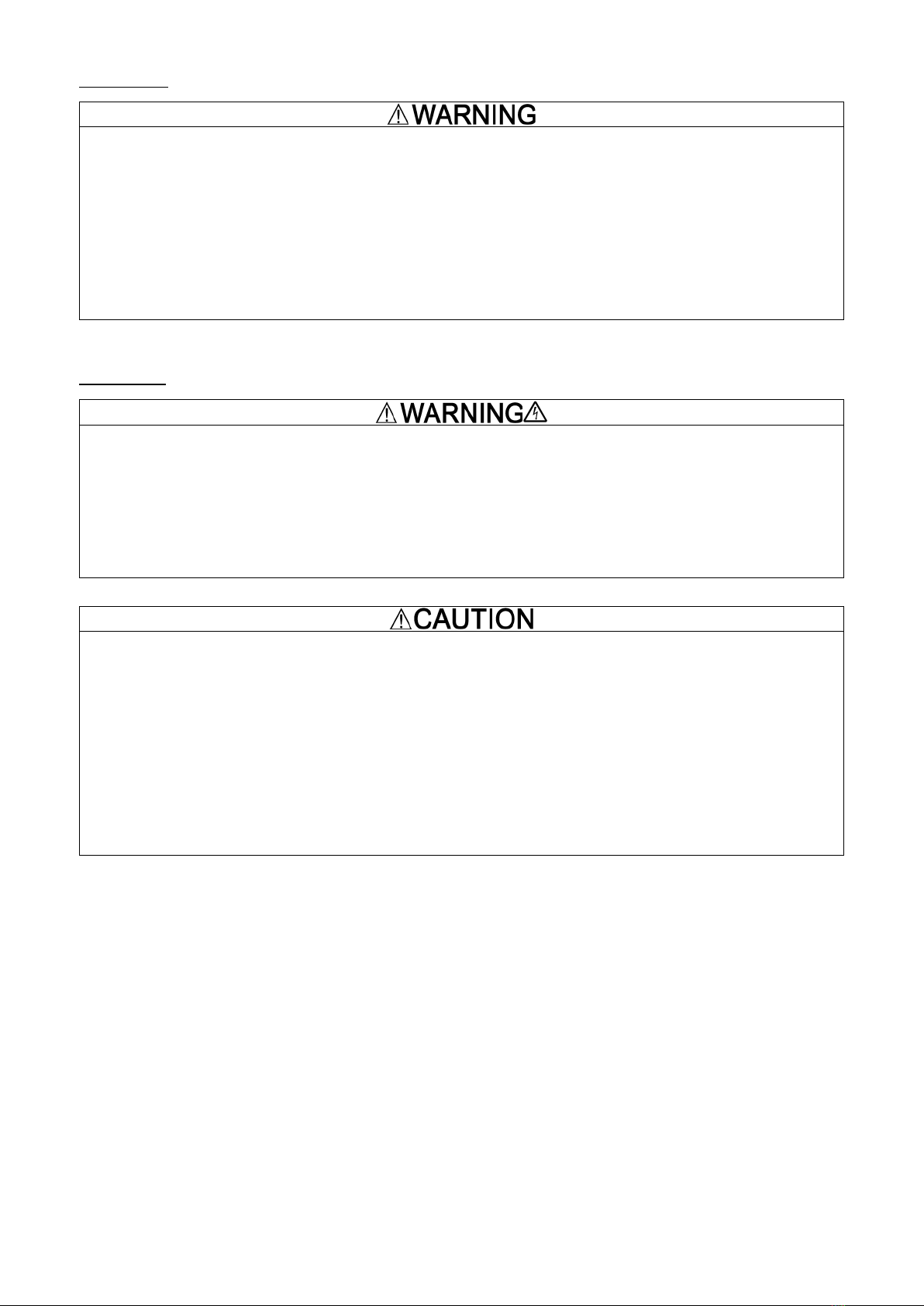
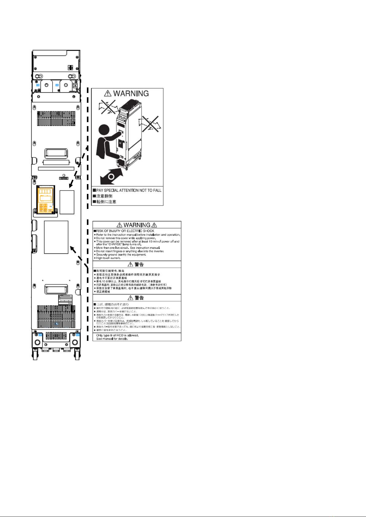
• Peripheral devices such as the filter stack, filtering resistors and reactors, and boosting reactors as well as the
heat sink become hot. NEVER touch these devices while the power is ON and immediately after the power is
turned OFF until they cool down.
Burns and injuries may result.
• Mount the fro
nt cover or the like without fail on the peripheral devices to keep them away from the reach of
people.
Electric shock or injury may result.
ii

Application
• The PWM converter is intended for use in combination with a Fuji inverter that drives a three-phase induction
motor, and must not be used for any other purposes.
Fire could result.
• The PWM converter may not be used for a life-support system or other purposes directly related to the human
safety.
•
Though the product is manufactured under strict quality control, install safety devices for applications where
serious accidents or property damages are foreseen in relation to the failure of it.
An accident could occur.
Installation
• Mount the converter on a base made of metal or other non-flammable material.
Otherwise, a fire could occur.
• Do not place flammable material nearby.
Doing so could cause fire.
• Install the converter in an inaccessible place, e.g., in a control panel.
Otherwise, electric shock or injuries could occur.
• Do not support the converter by its front cover during transportation.
Doing so could cause a drop of the converter and injuries.
•
Prevent lint, paper fibers, sawdust, dust, metallic chips, or other foreign materials from getting into the
converter or from accumulating on the heat sink.
Otherwise, a fire or an accident might result.
• Do not install or run a converter that is damaged or lacking parts.
Doing so could cause injuries.
• When changing the positions of the mounting bases, use the attached screws.
Otherwise, injuries could occur.
iii

Wiring
•
When wiring the converter to the power source, insert a recommended molded case circuit breaker (MCCB) or
residual-current-operated protective device (RCD)/earth leakage circuit breaker (ELCB) in the path of each pair
of power lines to the converter.
Otherwise, a fire could occur.
• Use the peripheral devices authorized by Fuji Electric for the converter.
Otherwise, a fire or bodily injuries could occur.
• Use wires in the specified size.
Otherwise, a fire could occur.
• Be sure to ground the converter's grounding terminals.
Otherwise, electric shock or fire could occur.
• Qualified electricians should carry out wiring.
Otherwise, an electric shock could occur.
• Ensure that the power is turned OFF (open circuit) before starting wiring.
Otherwise, an electric shock could occur.
• Be sure to complete installation of the converter before wiring.
Otherwise, an electric shock or injuries could occur.
• Never supply power to a converter whose parts are broken o
r coming off, or to a converter damaged in
transportation.
Doing so could cause an electric shock or fire.
• Never connect a DC reactor to the converter.
Doing so could cause a fire.
• Ensure that the number of input phases and the rated voltage of the product match the number of phases and the
voltage of the AC power supply to which the product is to be connected.
Otherwise, injuries could occur.
• Ensure that the polarity of the converter’s DC terminals (P(+) and N(-)) match that of the inverter’s ones.
Otherwise, an accident could occur.
• The converter, filter stack, inverter, motor and wiring generate electric noise. Be careful about malfunction of
the nearby sensors and devices. To prevent them from malfunctioning, implement noise control measures.
Otherwise, an accident could occur.
Operation
•
Be sure to mount the front cover before turning the power ON. Do not remove the cover when the converter
power is ON.
An electric shock could occur.
• Do not operate switches with wet hands.
Doing so could cause electric shock.
•
Confirm that the Run signal is OFF before resetting an alarm. Resetting an alarm with the Run signal being ON
may cause a sudden motor start.
An accident could occur.
• Never touch the terminals when the power is supplied to the converter, filter stack or peripheral devices even if
the converter is stopped.
An electric shock could occur.
iv

• Do not touch the heat sink, filtering resistors, filtering reactors or boosting reactors because they become hot.
Burns may result.
Maintenance and inspection, and parts replacement
•
Before proceeding to the maintenance/inspection, turn the power OFF, make sure that the charging lamp is
turned OFF. Further, make sure that the DC voltage across the terminals P(+) and N(-) and the terminal voltage
of the filtering capacitor is +25VDC or below.
Otherwise, an electric shock could occur.
• Always carry out the daily and periodic inspections described in the instruction/
user's manual. Use of the
inverter for long periods of time
without carrying out regular inspections could result in malfunction or
damage, and an accident or fire could occur.
• It is recommended that periodic inspections be carried
out every one to two years, however, they should be
carried out more frequently depending on the usage conditions.
•
It is recommended that parts for periodic replacement be replaced in accordance with the standard replacement
frequency indicated in the user's manual. Use of the product for long periods of time without replacement could
result in malfunction or damage, and an accident or fire could occur.
• Contact outputs [30A/B/C] and [Y5A/C] and [73A/C]
use relays, and may remain ON, OFF, or undetermined
when their lifetime is reached. In the interests of safety, equip the inverter with an external protective function.
Otherwise, an accident or fire could occur.
• Maintenance, inspection, and parts replacement should be made only by qualified persons.
• Take off the watch, rings and other metallic objects before starting work.
• Use insulated tools.
Otherwise, an electric shock or injuries could occur.
Disposal
• Treat the product as an industrial waste when disposing of it.
Otherwise, injuries could occur.
Others
• Never attempt to modify the product.
Doing so could cause an electric shock or injuries.
v

Location of General Precaution and Warning Labels
PWM Converter (RHC-D Series)
vi

Inside of the Products
PWM Converter (RHC-D Series)
If any of warning labels is torn, place an order for a new label with Fuji Electric and replace the torn label.
GENERAL PRECAUTIONS
Some drawings in this manual may be illustrated without covers or safety shields for explanation of detail parts.
Restore the covers and shields in the original state before using the products.
vii

Preface
Thank you for purchasing our PWM converter "RHC-D
series." This product is intended for use in combination
with a Fuji inverter (see the table below) as a
bidirectional device for converting AC current to DC
current and vice versa.
Read through this instruction manual to become
familiar with the handling procedure for correct use.
Improper handling might result in incorrect operation, a
short life, a failure of this product, or even substantial
property damage.
Even after reading this manual, read it again and again
whenever necessary. For this purpose, keep this manual
handy so that the user can refer to it any time.
If there is anything that you do not understand about the
product or this instruction manual, contact the store you
purchased or your nearest Fuji sales representative.
This instruction manual does not contain the
information on how to handle inverters. For the
information, refer to the inverter instruction manual.
List of applicable inverters
The table below lists the inverters that can be used in combination with this product.
The unit type and stack type of inverters can be used.
Inverter series Capacity Inverter type Stack/unit type
VG series All capacities FRNSVG1S-69stack type
viii

1Outline .......................................................... 1-0
2Before Use.................................................... 2-1
2.1 Acceptance Inspection ......................... 2-1
2.2 Appearance of the Product................... 2-3
2.3 Handling the Product............................ 2-5
2.4 Transportation....................................... 2-6
2.5 Storage Environment............................ 2-6
3Installation and Connection .......................... 3-1
3.1 Operating Environment ........................ 3-1
3.2 Installation and Layout ......................... 3-2
3.3 Connection ........................................... 3-5
3.3.1 General precautions about connection
....................................................... 3-5
3.3.2 Terminal functions ......................... 3-6
3.3.3 Terminal layout drawing ................ 3-8
3.3.4 Basic connection diagrams..........3-11
3.3.5 Details of connection................... 3-12
3.3.6 Precautions for installation..........3-21
3.3.7 Tightening torque and wire size for
devices applicable to the main circuit
.....................................................3-22
3.3.8 Peripheral devices.......................3-24
4Preparation for Operation............................. 4-1
4.1 Inspection and Preparation .................. 4-1
4.2 Driving Method ..................................... 4-1
4.3 Test Run ............................................... 4-1
5Operation Using the Keypad ........................ 5-1
5.1 Appearance.......................................... 5-1
5.2 Operation and Display Screen ............. 5-2
5.2.1 Screen immediately after auxiliary
control power supply is turned on . 5-2
5.2.2 Screen immediately after the main
circuit power supply is turned on... 5-3
5.2.3 Switching LED monitor screens .... 5-4
5.2.4 Switching LCD screens................. 5-5
5.2.5 Configuring function code data ..... 5-6
5.2.6 Checking function code settings ... 5-9
5.2.7 Monitoring the running status...... 5-10
5.2.8 Checking I/O signal states ...........5-11
5.2.9 Displaying maintenance information5-12
5.2.10 Measuring load factor..................5-14
5.2.11Displaying alarm information....... 5-15
5.2.12 Displaying alarm history and cause5-17
5.2.13 Copying data ............................... 5-18
6Description of Function Codes ..................... 6-1
6.1 Function Code Tables........................... 6-1
6.2 Details of Function Codes .................... 6-3
7Troubleshooting............................................ 7-1
7.1 List of Protective Functions .................. 7-1
7.2 Error Reset ........................................... 7-3
7.3 Troubleshooting.................................... 7-4
7.4 Converter Cannot Get Ready to Run.7-12
8Maintenance and Inspection......................... 8-1
8.1 Daily Inspection.................................... 8-1
8.2 Periodic Inspection............................... 8-2
8.3 Measurement of Electrical Quantity in Main
Circuit ................................................... 8-4
8.4 Insulation Test....................................... 8-5
8.5 Replacement Parts............................... 8-6
9Control Options............................................. 9-1
9.1 Common Specifications........................ 9-1
9.1.1 Option list ...................................... 9-1
9.1.2 Acceptance inspection .................. 9-1
9.1.3 Installing a built-in option (OPC-VG7)9-2
9.2 T-Link Option......................................9-10
9.2.1 Product overview......................... 9-10
9.2.2 Model and specifications..............9-11
9.2.3 Specifications...............................9-11
9.2.4 External view............................... 9-12
9.2.5 Basic connection diagram........... 9-13
9.2.6 Function codes............................ 9-15
9.2.7 Protective operation.................... 9-15
9.3 SX Bus Option.................................... 9-16
9.3.1 Product overview......................... 9-16
9.3.2 Model and specifications............. 9-17
9.3.3 Specifications.............................. 9-17
9.3.4 External view............................... 9-19
9.3.5 Basic connection diagram........... 9-20
9.3.6 Function code.............................. 9-22
9.3.7 Protective operation.................... 9-23
9.4 CC-Link Option................................... 9-24
9.4.1 Product overview......................... 9-24
9.4.2 Model and specifications............. 9-25
9.4.3 Specifications.............................. 9-25
9.4.4 External view............................... 9-27
9.4.5 Basic connection diagram........... 9-28
9.4.6 Protective operation.................... 9-29
9.5 DIO Option ......................................... 9-31
9.5.1 Outline of product........................ 9-31
9.5.2 Model and specifications............. 9-32
9.5.3 Specifications.............................. 9-32
9.5.4 Dimensioned drawing ................. 9-33
9.5.5 Basic connection diagram........... 9-35
9.5.6 Function codes............................ 9-36
9.5.7 9.5.7 Check function ................... 9-36
9.6 AIO Option.......................................... 9-37
9.6.1 Outline of product........................ 9-37
9.6.2 Model and specifications............. 9-38
9.6.3 9.6.3 Specifications..................... 9-38
9.6.4 Dimensioned drawing ................. 9-39
9.6.5 Basic connection diagram........... 9-40
9.6.6 Function codes............................ 9-41
9.6.7 Check function ............................ 9-41
9.7 SI Option ............................................ 9-42
9.7.1 Product overview......................... 9-42
9.7.2 Model .......................................... 9-42
9.7.3 Specifications.............................. 9-43
9.7.4 External drawings........................ 9-44
9.7.5 Connection.................................. 9-45
9.7.6 Basic connection diagram........... 9-49
9.7.7 Operation .................................... 9-50
9.7.8 Protection functions .................... 9-52
9.8 SIR Option.......................................... 9-54
9.8.1 Product overview......................... 9-54
9.8.2 Model .......................................... 9-54
9.8.3 Specifications.............................. 9-55
9.8.4 External drawings........................ 9-56
10 Specifications.............................................. 10-1
10.1 Standard Specifications...................... 10-1
10.2 Common Specifications...................... 10-2
10.3 External Dimensions .......................... 10-4
10.4 Generating Loss................................. 10-6
11 Function Code Tables..................................11-1
11.1 Function Code Configuration ..............11-1
11.2 Function Code Tables..........................11-1
11.3 List of Communication-dedicated Function
Codes..................................................11-7
11.4 Data Format List..................................11-8
12 CONFORMITY WITH STANDARDS.......... 12-1
12.1 Compliance with European Standards ( )
12-1

1 Outline
Outline of Product
The high power factor PWM converter with power
regenerative function, the RHC-D series is used in
combination with a Fuji inverter to return the
regenerative energy generated on the load side to the
power source, improving the regenerating performance
and saving energy.
The converter shapes an input current waveform into a
sinusoidal waveform to enable driving at a power factor
of almost 1 so that it is possible to reduce the capacity
of the power supply equipment.
As well, the converter is useful for the replacement of
conventional applications using braking resistors, such
as cranes and vertical transfer machines and it is
compliant with the "Guideline for Suppressing
Harmonics by Customers Receiving High Voltage or
Special High Voltage" (conversion coefficient Ki = 0).
With simplified operation, it is possible to monitor the
input power supply, current, power, and load factor,
configure function codes, and check alarm history.
Various communications options provided allow you to
monitor data from a remote site easily or to integrate
the converter in the customer's system without
difficulty.
The converter also applies to large capacity,
low-voltage inverters by controlling sharing of load to
the inverter uniformly with the parallel connection
option and input transformer.
Guideline for Suppressing Harmonics
The PWM control regulates the power supply current
into a sinusoidal wave to contribute to substantial
reduction of harmonic currents.
Accordingly, the combination with an inverter can
handle the conversion coefficient Ki (specified in the
"Guideline for Suppressing Harmonics by Customers
Receiving High Voltage or Special High Voltage" issued
by the Ministry of Economy, Trade and Industry) as "0"
(that is, no generation of harmonics).
Possible to Reduce the Capacity of Power
Supply
By controlling the power factor, the converter supplies
the in-phase current relative to the power phase voltage,
enabling running at a power factor of almost 1. This
makes it possible to reduce the capacity of the power
transformer or the size of the devices to less than those
of the standard inverters.
Substantial Increase of Braking
Performance
The regenerative energy obtained in frequent
acceleration/deceleration operation or elevator returns
to the power supply side, promoting energy savings.
Since the waveform of the regenerative current is
sinusoidal wave, too, there is no need to be anxious
about trouble in the power supply system.
MD mode LD mode
Continuous
regeneration
100% 100%
Short time rating
1 min. 150% 1 min. 110%
Variety of Assured Functions
• Monitors the source voltage, current, power, power
supply frequency and other trends.
• Provides three choices of languages (Japanese,
English and Chinese) to be displayed on the panel.
• Saves the converter load factor calculated,
cumulative run time, and data at the occurrence of
alarm into the memory.
• Issues overload and converter overheat early warning
signals before the converter stops due to an alarm.
• Shuts down the gate output at the time of a
momentary power failure and restarts operation
immediately after the power is restored.
• Supports various communications protocols (T-Link,
SX bus, CC-Link and RS-485)
1-0

2 Before Use
•
Inadequate handling of the product during lifting or transportation will cause injuries or breakage of the
product. Trained personnel must handle the product, using suitable devices.
Injury may result.
2.1 Acceptance Inspection
Unpack the package and check if the converter unit, filter stack and peripheral devices are what you ordered and they
are free from damage. Also check that the models of the filter stack and peripheral devices match the converter type,
referring to Section 3.3.8 "Peripheral devices."
If you suspect the product is broken or not working properly or if you have any questions about your product, contact
your dealer or nearest Fuji sales representative and give him/her information about the following items.
(1) PWM converter
Check that the converter is the type you ordered. You can check the type and specifications on the rating plate shown
in Figure 2.1-1. The keypad comes with the converter unit.
TYPE: Type of PWM converter
RHC 355 S – 69 D E
SOURCE : Power supply rating
OUTPUT : Output rating
WEIGHT: Mass
SER. No. : Product number Manufacturing date
3 3 A4 5 6 A 0 0 0 1 P J <3 1 1> Production week
This indicates the week number that is numbered from 1st week of January.
The 1st week of January is indicated as '01'.
Production year: Last digit of year
:Compliance with European Standards (See Chapter 12)
Figure 2.1-1 Rating Plate
- Models of the converter, filter stack, and peripheral devices
- Serial number (See below.)
- Date of purchase
- Inquiries (for example, point and extent of breakage, uncertainties, failure phenomena,
and other circumstances)
Shipping destination/Instruction manual language
J: Japan/
Japanese, E: EU/English, C: China/Chinese
Series name
D series
Power supply voltage
69: 690V class
Stack type
S: Standard stack
Standard applied inverter capacity
355: 355 kW
Product model
RHC
2-1

(2) Optional devices
The following items are options.
- Control options (OPC-VG7-TL, OPC-VG7-CCL, OPC-VG7-SX, OPC-VG7-SI, OPC-VG7-SIR, OPC-VG7-DIO,
and OPC-VG7-AIO)
2-2

2.2 Appearance of the Product
PWM converter
Figure 2.2-1 Appearance of Converter (RHC132S to 200S-69DE (Rank 3))
Sub nameplate
Main
circuit
terminal
block
Casters
Cooling fans
P (+) bar
N (-) bar
Hoist hole
(
φ
26)
Hoist hole
(φ26)
Handle
Keypad
Handle
Front cover
Main
nameplate
Hoist hole
(φ26)
Hoist hole
(φ26)
Hoist hole
(φ26)
2-3

Figure 2.2-2 Appearance of Converter (RHC250S to 450S-69DE (Rank 4))
Sub nameplate
Main circuit
terminal
block
Casters
Cooling fans
Hoist hole
(φ26)
P (+) bar
N (-) bar
Hoist hole
(φ26)
Hoist holes
(φ26)
Main
nameplate
Keypad
Hoist hole
(φ26)
Hoist hole
(φ26)
Handle
Handle
Front cover
2-4

2.3 Handling the Product
(1) Removing the front cover
Loosen the front cover mounting screws and remove the front cover.
When removing the front cover from the PWM converter, slide the blanking cover beneath the keypad down
beforehand as shown in the lower right figures.
Figure 2.3-1 Removal of Front Cover
(2) Removing the keypad
Loosen the keypad mounting screws, insert your finger into the cutout provided in the front cover and remove the
keypad slowly. Rough handling may break the connectors.
Figure 2.3-2 Removal of Keypad
Front cover
Keypad mounting screws
Loosen the screws on the
blanking cover beneath the
keypad.
Slide the blanking cover
down
.
2-5

2.4 Transportation
Do not hold the covers or components during
transportation.
The converter may fall or turn over, causing
injuries.
When carrying the product, be sure to hold the handles
(provided on the front side) or the rear side of the unit.
Holding the covers or components may fall or turn over
the product. When carrying the product with casters, in
particular, take extra care for avoiding turnover.
To use a hoist or crane for carrying the product, pass the
hook or rope through hoist holes.
Figure 2.4-1 Carrying
Direction and Location of Handles
2.5 Storage Environment
(1) Temporary storage
Store the product in an environment that satisfies the
requirements listed below.
Table 2.5-1 Storage Environment
Item
Specification
Ambient
temperature
-10 to + 40°C
Places not subjected to
abrupt temperature changes
or condensation or freezing
Storage
temperature
(Note 1)
-25 to + 70°C
Relative
humidity
5 to 95%
(Note 2)
Atmosphere
The product must not be exposed to dust,
direct sunlight, corrosive or flammable gases,
oil mist, vapor, water drops or vibration. The
atmosphere must contain only a low level of
salt.
Note 1: Assuming comparatively short-time storage, e.g.,
during transportation or the like.
Note 2: Even if the humidity is within the specified
requirements, avoid such places where the product will be
subjected to sudden changes in temperature that will cause
condensation to form.
Precautions for temporary storage
1) Do not leave the product directly on the floor.
2) If the environment does not satisfy the specified
requirements listed above, wrap the product in an
airtight vinyl sheet or the like for storage.
3) If the product is to be stored in a high-humidity
environment, put a drying agent (such as silica gel)
in the airtight package described in item 2).
(2) Long-term storage
The long-term storage method of the product varies
largely according to the environment of the storage site.
General storage methods are given below.
1) The storage site must satisfy the requirements
specified for temporary storage.
However, for storage exceeding three months, the
ambient temperature range should be within the
range from -10 to 30°C. This is to prevent
electrolytic capacitors in the product from
deterioration.
2) The package must be airtight to protect the product
from moisture. Add a drying agent in the package to
maintain the relative humidity inside the package
within 70%.
3) If the product has been installed to the equipment or
panel at construction sites where it may be subjected
to humidity, dust or dirt, then temporarily remove
the product and store it in a preferable environment.
4) If the product has not been powered on for a long
time, the property of the electrolytic capacitors may
deteriorate. Power the product on once a year.
Handle
Handle
Rear of the unit
Carrying
direction
2-6

3 Installation and Connection
3.1 Operating Environment
Install the converter in an environment shown in Table 3.1-1.
Table 3.1-1 Environmental Requirements
Item Specifications
Site location Indoors
Ambient temperature -10 to +40°C
Relative humidity 5 to 95% (No condensation)
Atmosphere
The converter must not be exposed to dust, direct sunlight, corrosive gases, flammable gases,
oil mist, vapor or water drops.
The atmosphere can contain a small amount of salt.
The converter must not be subjected to sudden changes in temperature that will cause
condensation to form.
Altitude 1000 m max.
(Refer to Table 3.1-2 for altitudes exceeding 1000 m.)
Vibration 2 to 9 Hz: 0.3 mm (Max. amplitude)
9 to 200 Hz: Less than 1 m/s2 (0.1 G)
Table 3.1-2 Output Current Derating Factor in Relation to Altitude
Altitude Output current derating factor
1000 m or lower 1.00
1000 to 1500 m 0.97
1500 to 2000 m 0.95
2000 to 2500 m 0.91
2500 to 3000 m 0.88
3-1
This manual suits for next models
2
Table of contents
Other Fuji Electric Media Converter manuals
Popular Media Converter manuals by other brands

Manhattan
Manhattan 158282 user manual

MRC
MRC 0001822 quick start guide

Cobalt Digital Inc
Cobalt Digital Inc openGear 9034 owner's manual

TR-Electronic
TR-Electronic CEV65M-4096/4096 SSI 36ZB10FL manual

RGBlink
RGBlink UMS4 plus user manual

Miranda
Miranda DENSITE IRD-3802 Guide to installation and operation