- 1 -
Preface
We thank you very much for purchasing Fuji’s NO2/NO
Converter.
●Please read this instruction manual thoroughly
before installing, using and applying maintenance
this device.
Damage or accident may be caused when
mishandled.
●Specification of this NO2/NO converter may alter
without notice for modification.
●Do not remodel or modify this NO2/NO converter
without the manufacturer’s permission. Fuji Electric
will not accept any liability whatsoever for any
trouble or accident caused by such modification.
●Operator of the NO2/NO converter should keep this
instruction manual.
●Operator should keep this instruction manual near at
hand at all times, after thoroughly reading it.
Safety precautions
Please read the safety precautions written as bellow
before use, for correct use of the converter.
Please observe cautions stated bellow, for it contains
important information on safety.
CAUTION
CAUTION
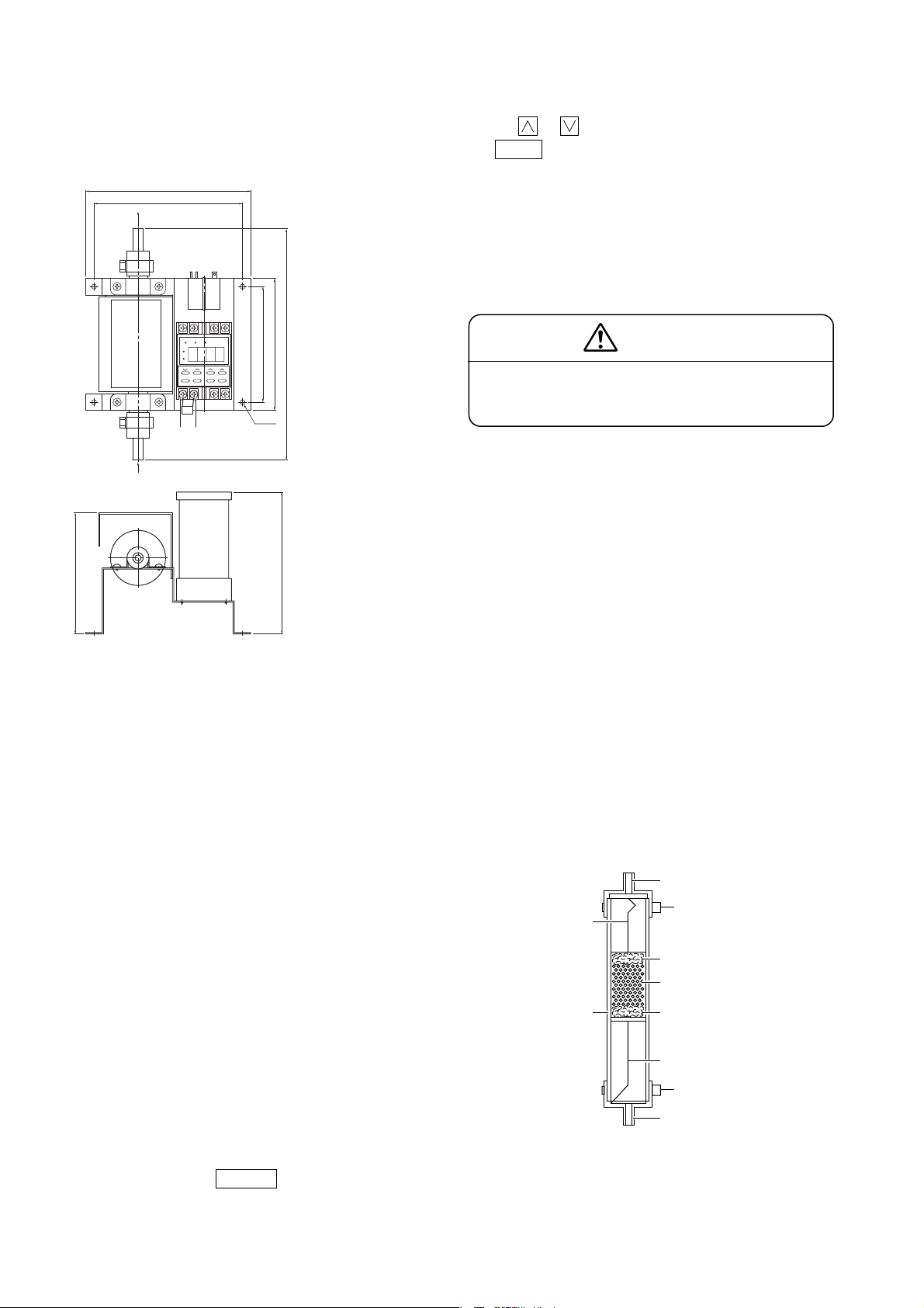
1. Overview
The NO2/NO converter is to be coupled with a NOx gas
analyzer or NH3gas analyzer for flue exhaust. It is
converter using a special catalyst which efficiently
converts NO2in sample gas to NO.
2. Major Specifications
Catalyst : Carbon, replacement required every
8 months (when NO2concentration
is 10 ppm or lower)
Gas flow rate : About 0.5L/min.
Set temperature : 220±10°C
Thermocouple : K
Power supply : 100V AC, 50/60Hz
Power consumption : About 85VA
Material of parts that contact gas
: Ceramic, Viton, Glass wool,
SUS316
Gas inlet/outlet connection method
: Insert Teflon tube φ6 mm/φ4 mm
into Viton connection port of inner
diameter φ5.5 mm. (Withstand
pressure: 10 kPa)
NO2 / NO Converte
INZ-TN1ZDL03-E
INSTRUCTION MANUAL
●Installation, wiring and piping should be carried
out by professionals or suppliers. Incomplete
installation may cause fall of the device, electric
shock or fire.
●Gas analyzer should be turned OFF when wiring,
maintenance or inspection is carried out. This is to
prevent electric shock and injury.
●Use wires with proper wire rods and diameters
that meets this device. Wrong ones may cause
electric shock or fire.
●Do not insert metal rod or fingers to the power
supply terminal. It may cause electric shock.
●Remove any metal objects such as wristwatch
while operating maintenance or inspection. It may
cause electric shock.
●Use pipes with proper material and joints stated in
the instruction manual. It may cause gas leakage.
●Use replacement parts that are specified by the
manufacturer. Otherwise, it may cause
malfunction, electric shock or gas leakage.
●Do not touch the converter section, due to high
temperature. Wear protective gloves while
exchanging catalyst. It may cause burn injury.
Model: ZDL03
Precautions under this mark is stated
when wrong handling may cause
hazardous situation. Possibility of
Medium level damage or injury, and
physical damage is predicted.
CAUTION
Head Office
Gate City Ohsaki, East Tower, 11-2, Osaki 1-chome,
Shinagawa-ku, Tokyo 141-0032, Japan
http://www.fesys.co.jp/eng
Instrumentation Div.
International Sales Div.
No. 1, Fuji-machi, Hino-city, Tokyo 191-8502, Japan
Phone: 81-42-585-6201, 6202 Fax: 81-42-585-6187
http://www.fic-net.jp/eng