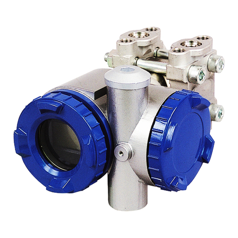
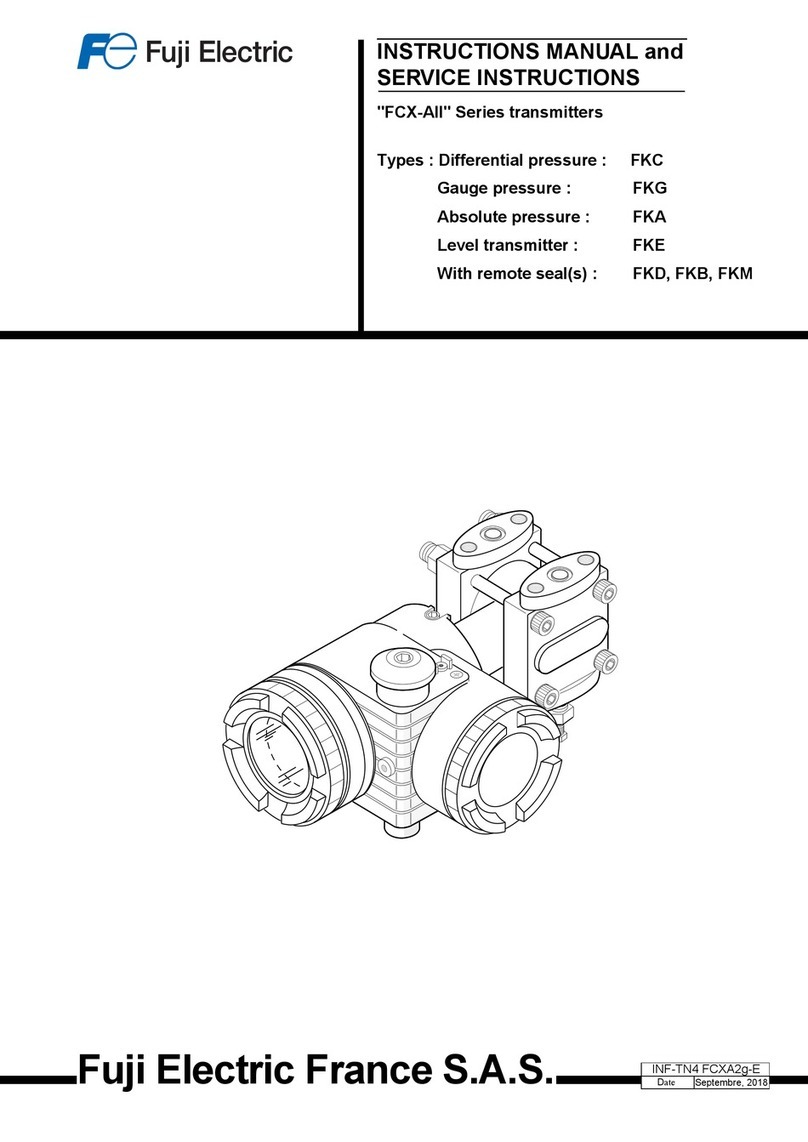
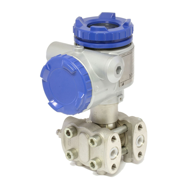
Fuji Electric FCX-AIV Series User manual

Fuji Electric France S.A.S. INF-TN6FCXA4b-E
DATE July 18 2023
Instruction Manual
Standard process covers
FKC, FKG, FKA
Direct mount
FKP, FKH
With remote seal
FKE, FKD, FKB, FKM, FKP, FKH
Pressure transmitters
with safety functions
FCX-AIV


INF-TN6FCXA4b-E 1
INTRODUCTION
Thank you very much for purchasing FCX-AIV series of pressure transmitters with safety functions.
Read this manual carefully before proceeding with the installation, commissioning and maintenance
of the FCX-AIV transmitters.
•
prior notice for product improvements.
•
• This manual should be kept by the persons in charge of installation,
commissioning and maintenance.
• This manual is available at anytime on the
or by reading the QR Code located on the cover of the terminal block.
•
and general arrangement drawings, please refer to the dedicated datasheets.
• Transcription of all or part of this manual is prohibited.

2 INF-TN6FCXA4b-E
① Tag No: TAG number
② Model: Model code
③ Range: Calibrated range and/or maximum cell measuring range
④ Power Supply: Power supply range or maximum value (may depend of the type of approval)
⑤ Output: Output type (for example 4-20 mAdc)
⑥ M.W.P: Maximum Working Pressure
⑦ Ser.No: Transmitter serial number
⑧ OAN: Oder Acknowledgement Number
⑨ Mfd: Manufacturing Date
⑩ Type of approval description
⑪
TRANSMITTER IDENTIFICATION
main characteristics of the transmitter and possibly the type of approval with the related parameters.
IP66/67
Model
Range
Output
Power Supply
M.W.P Mfd
OAN
Ser.No. 338B365
Assembled in France (F-63039 Clermont-Ferrand) Fuji Electric France S.A.S.
①
②
③
④
⑤ ⑧
⑥ ⑨
⑪
⑩
⑦

INF-TN6FCXA4b-E 3
GENERAL RECOMMENDATIONS
1. Storage for a long period:
Store the transmitter in a dry room with normal temperature and humidity.
Keep protective caps in place at electrical conduits and process connections.
2. Select the appropriate place for installation:
The location of the on-site installation should provide a minimum level of vibrations
and limitation of exposure to dust and corrosive atmospheres.
The location should also allow an easy access for setup and maintenance of the transmitter.
3. Monting position:
4. Beware of overpressure:
Please carrefully check the Maximum Working Pressure (MWP) of the transmitter.

4 INF-TN6FCXA4b-E
GENERAL SAFETY INSTRUCTIONS
For your own safety and the correct use of the FCX-AIV pressure transmitters, please carrefuly
read the following general recommendations:
1. The risks related to a non-respect of the instructions
povided in this manual are ranked and identied as follow:
2. Applications in hazardous locations (potentially explosive atmospheres)
FCX-AIV serie
and protection modes.
transmitters.
Please refer to the dedicated datasheet for further details on protection mode and related
parameters.
3. Magnetic stick (contacless setting)
• Do not use this magnetic stick if you have a medical device such as a pacemaker.
•
4. Safety Instrumented Systems
to IEC 61508 and IEC 61511 standards.
For evaluation of your safety instrumented system, please refer to the FCX-AIV Safety Manual
(TN5A5137) for further details on FMEDA results, failure rates and expected product lifetime.
instructions are not followed.
or physical damage can happen.
Important instructions to be respected.
General observations concerning the product,
product handling and correct use of the transmitter.
DANGER
WARNING
INDICATION
CAUTION
DANGER
WARNING
INDICATION
CAUTION
DANGER
WARNING
INDICATION
CAUTION
DANGER
WARNING
INDICATION
CAUTION

INF-TN6FCXA4b-E 5
TABLE OF CONTENTS
INTRODUCTION
TRANSMITTER IDENTIFICATION
GENERAL RECOMMANDATIONS
GENERAL SAFETY INSTRUCTIONS
TABLE OF CONTENT
1. PRODUCT OVERVIEW
1.1
1.2 Items displayed by the optional local indicator
1.3
2. INSTALLATION AND PIPING
2.1 Installation
2.1.1 Mounting bracket
2.1.2 Pipe mounting
2.1.3 Flanged mounting (rigid assembly)
2.1.4 Wall mounting
2.2 Change the orientation of the transmitter housing
2.3 Space around the transmitter
2.4 Change the position of the vent/drain plug
2.5 Piping
2.5.1
2.5.2 Gauge and absolute pressure transmitters (models FKG and FKA)
2.5.3
2.5.4 Remote seal type pressure transmitters (models FKE, FKD, FKB and FKM)
3. WIRING
3.1 Wiring procedure
3.2 Electrical conduit
3.3 Power supply and load resistance
3.4 Grounding
4. COMMISSIONING AND SHUTDOWN
4.1
4.2 Commissioning
4.2.1
4.2.2 Gauge and absolute pressure transmitters
4.3 Shutdown
4.3.1
4.3.2 Gauge and absolute pressure transmitters
5. TRANSMITTER SETTINGS
5.1
5.1.1
5.1.2
5.2 Using the local indicator
5.2.1 Menu list
5.2.2 Switching menus
5.2.3 Operating procedure
5.3
5.3.1
5.3.2
5.3.3
6. MAINTENANCE
6.1 Periodic inspection
6.2 Proof Test (IEC 61508/IEC 61511)
6.3 Troubleshooting
6.4 Replacement of defective parts
6.5 Calibration
6.6 Default factory settings
P. 1
P. 2
P. 3
P. 4
P. 5
P. 6
.7
.8
.9
P. 10
.10
.10
.11
.12
.12
.12
.13
.13
.14
.14
.16
.18
.19
P. 24
.24
.25
.26
.26
P. 27
.27
.27
.27
.27
.28
.28
.28
P. 29
.29
.29
.30
.31
.32
.33
.34
.65
.65
.65
.66
.70
P. 71
.71
.71
.72
.73
.79
.82

6 INF-TN6FCXA4b-E
Manual Zero/Span Adjustment
Write protection setting switch
4-20mA signarl
Control system
HHC
EEPROM
Sensor
parameters
Analog to
Digital
Converter
Digital to Analog
Converter
Micro Processor
・Signal conditioning
・Reranging
・Diagnositics
・Communicaiton
HART®
Communication
EEPROM
Transmitters
Parameters
Sensor Unit
(Detecting unit) Amplifier Unit
LCD digital indicator
(option)
Micro
Capacitance
Silicon Sensor
HPLP
High pressure
side
Low
pressure
side
PRODUCT OVERVIEW
1
combination with state-of-the-art digital signal processing to provide exceptional performances,
high functionnality and reliability.
screw located on the transmitter housing.
Measuring principle
The operating principle of the FCX-AIV pressure transmitter is shown in the block diagram below.
The input pressure is detected by the micro-capacitive silicon sensor and then converted by the

INF-TN6FCXA4b-E 7
1PRODUCT OVERVIEW
1.1 Amplier unit and junction block
1
Amplifier unit
Indicator
Zero/Span selection switch
Write Enable/Disable setting switch S D
Z E
LCD unit connector
Display only Display and settings
Vent/drain
plug Adjustment screw
Detecting unit
Process connection
Jonction block
Amplifier unit
Amplier unit
Item Description
Used to connect the optional digital indicator.
Zero/Span selection switch
Write Enable/Disable
selection switch
Junction block
Symbol Description
Terminal used for grounding (hearth)

8 INF-TN6FCXA4b-E
2PRODUCT OVERVIEW
1
1.2 Items displayed by the optional local indicator
Item When displayed When not displayed
%
The displayed value is
a percentage of the span The displayed value is in engineering units
ZERO
SPAN
DISP √The displayed value is in square root mode The displayed value is in linear mode
OUT √The 4-20 mA output is in square root mode The 4-20 mA output is in linear mode
FIX Fixed current mode Measurement mode
abs Absolute pressure Gauge pressure
Measurement value < Zero
Write protect mode is enabled Write protect mode is disabled
The transmitter is in normal
(measurement) mode
Span bargraph (0 to 100%, in 5% increments of the calibrated span)
Engineering unit
Write protect
Zero or span
adjustment mode
PV value
Square root mode
(4-20 mA output and display)
Engineering unit
Write protect
Zero or span
adjustment mode
PV value
Square root mode
(4-20 mA output and display)
Engineering unit
Write protect
Zero or span
adjustment mode
PV value
Square root mode
(4-20 mA output and display)
Engineering unit
Write protect
Zero or span
adjustment mode
PV value
Square root mode
(4-20 mA output and display)
Engineering unit
Write protect
Zero or span
adjustment mode
PV value
Square root mode
(4-20 mA output and display)

INF-TN6FCXA4b-E 9
2PRODUCT OVERVIEW
1
1.3 Operating modes of the local display with conguration switches
Normal mode (the transmitter is performing measurements)
Conguration mode
Functions of the three sets of switches
Each function can be managed by two redondant switches:
One push-button and one magnetic switch.
•
•
Fonction Description
M (Mode)
Validates a new parameter setting value.
- (Minus)
+ (Plus)
MODE
Push-button Push-button
Magnetic switch
Push-button
Magnetic switch
Magnetic switch
Blinking
PV value
Menu nb
Menu name
MODE
Push-button Push-button
Magnetic switch
Push-button
Magnetic switch
Magnetic switch
Blinking
PV value
Menu nb
Menu name
MODE
Push-button Push-button
Magnetic switch
Push-button
Magnetic switch
Magnetic switch
Blinking
PV value
Menu nb
Menu name

10 INF-TN6FCXA4b-E
2INSTALLATION AND PIPING
2
2.1 Installation
During the unpacking of the transmitter, check the conformity of the transmitter and all the accessories.
Before installation, the customer must check the compatibility of the wetted parts with the application.
2.1.1 Mounting bracket
Depending the type of transmitter, the mounting bracket can be assembled as shown below.
•
transmiter with standard process covers
(FKC, FKG and FKA models):
•
transmiter with capillary and remote seal
(FKD, FKB and FKM models):
Process cover
Bracket
Plain washer
Spring washer
Mounting bolt
(M8×12)
Transmitter
Transmitter
Bracket
Plain washer
Spring washer
Mounting bolt
(M8×12)
If the transmitter is to be stored before the installation,
leave it packed in a room with normal temperature
• The transmitter is heavy. Be carreful when handling it.
• The transmitter should be installed in a place that meets
• Process connections must match with the process
temperature and pressure.
• The measuring diaphragms are very sensitive.
Be carrefull when handling.
Potentially explosive atmospheres :
• Check that the protection mode corresponds
whith the type of process and installation area.
• Flameproof protection mode :
the magnetic stick.
DANGER
WARNING
INDICATION
CAUTION
DANGER
WARNING
INDICATION
CAUTION
DANGER
WARNING
INDICATION
CAUTION

INF-TN6FCXA4b-E 11
2INSTALLATION AND PIPING
2
• Gauge and absolute direct
mount type pressure transmitters
2.1.2 Pipe mounting
• Standard process cover type
(FKC, FKG and FKA models):
• Remote seal type
(FKD, FKB and FKM models):
• Direct mount type
Bracket
Plain washer
Spring washer
Mounting bolt
(M4×10)
Transmitter
Adaptor (Option)
U-Bolt

12 INF-TN6FCXA4b-E
2INSTALLATION AND PIPING
2
2.1.3 Flanged mounting (rigid assembly)
• Transmitters with remote seal
rigid assembly, FKE level transmitter.
Flange bolting and gasket are not
provided with the transmitter.
2.1.4 Wall mounting
• Fasten to the wall using the U-bolt holes and M8 bolts.
2.2 Change the orientation of the transmitter housing
Nut
Spring washer
Plain washer
Bolt
Transmitter
Rotate the transmitter
clockwise by 90°.
Rotate the transmitter
counterclockwise by 90°.
Potentially explosive atmosphere:
•
by steps of 90°. Before rotating the housing, it is
damaging the ribbon cable of the measuring cell
DANGER
WARNING
INDICATION
CAUTION
DANGER
WARNING
INDICATION
CAUTION
1. Remove the housing cover and
2.
(M6 x 12) of the transmitter housing.
3. Rotate the housing in 90°
steps to the desired orientation.
4.
srews of the housing.
5.
and replace the housing cover.

INF-TN6FCXA4b-E 13
2INSTALLATION AND PIPING
2
2.3 Space around the transmitter
Make sure there is enough space around the transmitter to facilitate wiring and maitenance.
2.4 Change the position of the vent/drain plug
Unscrew slowly the vent/drain plug.
Clean the thread and reapply sealing tape (4 turns, 1/10 mm tickness)
before screwing the vent/drain plug back on.
Tightening torque : 30 N.m (3 kgf.m) <18ft.lb>
500 500
500
Unit: mm
Process connection

14 INF-TN6FCXA4b-E
2INSTALLATION AND PIPING
2
2.5 Piping
For optimal operation and measurment, the connection to the process piping
must respect the following rules:
1. For liquid or steam monitoring, the transmitter must be installed below the process piping.
2. For gas monitoring, the transmitter must be installed above the process piping.
2.5.1 Dierential pressure and ow transmitters (model FKC)
Check the high and low pressure sise on the transmitter:
Remove the protective cap:
sure to remove the caps. When removing the caps, carefully protect the threaded portion and
sealing face from damage.
Connection of the transmitter to the impulse pipes:
1.
7/16-20UNF bolts, and then the impulse pipes must be connected to the manifold valve.
Tightening torque of the 7/16-20UNF bolts should be 30 to 40 Nm (3 to 4 kgf m).
2. If a manifold is not used, the impulse pipes can be directly screwed into the transmitter process
should be 30 to 40 Nm (3 to 4 kgf m).
All parts, including transmitters, valves and manifolds, to be
connected to the process line must be selected to comply with
the piping class and maximum working pressure (MWP). If the
DANGER
WARNING
INDICATION
CAUTION
H L
Threaded part
Sealing surface

INF-TN6FCXA4b-E 15
2INSTALLATION AND PIPING
2
Positions of the process connection:
Please refer to the drawings below for further details for gas, liquids and steam measurment.
Typical examples of process piping connections:
• Gas ow measurement
Standard process cover type.
Place the transmitter above the process piping.
If the process temperature is high,
please use condensers.
• Liquid ow measurement
Place the transmitter below the process piping.
Make piping so that gas bubbles that might be
present in the impulse pipes cannot reach the
transmitter.
• Steam ow measurement
Install two condensers at the same height near
the piping connexion. Fill the pipes between
the condensers and the transmitter with water.
Gas Liquid Steam
Upper
Lower
Upper
Lower
Main process piping
Connections on the upper
side (0 to ± 45° from the
vertical)
Connections on the lower
side (0 to - 45° from the
horizontal)
Connections on the upper
side (0 to + 45° from the
horizontal)
Orifice plate
Manifold
Impulse pipe
Isolating valve
Process pipe
Orifice plate
Impulse pipe
Manifold
Isolation valve
Process pipe
Isolation valve Process pipe
Condenser
Manifold Impulse pipe

16 INF-TN6FCXA4b-E
• Level measurement: The reference column is lled
Connect the high level connection of the tank to the low pressure connection of the transmitter,
and the low level connection of the tank to the high pressure connection of the transmitter.
0% point).
100% point).
3).
• Level measurement: The reference column is empty
For an open tank, the low pressure of the transmitter is left at the atmospheric pressure.
h
0% point).
100% point).
3).
H
1
H
2
ρ
0
ρ
h
ρ
1
Max. liquid level
Min. liquid level
Condensor
High pressure
side
Low pressure
side
Equalizing
valve
Equalizing
valve
Max. liquid level
Min. liquid level
Atomospheric
air inlet
Low pressure
side
High pressure side
H1
ρ
h
ρ1
2INSTALLATION AND PIPING
2
2.5.2 Gauge and absolute pressure transmitters (models FKG and FKA)
Remove the protective cap:
a protective cap. Before piping, be sure to remove the cap.
When removing the cap, carefully protect the threaded portion
and sealing face from damage.
Connection of the transmitter to the impulse pipe:
Threaded part
Sealing surface

INF-TN6FCXA4b-E 17
2INSTALLATION AND PIPING
2
Gas Liquid Steam
Upper
Lower
Upper
Lower
Main process piping
Connections on the upper
side (0 to ± 45° from the
vertical)
Connections on the lower
side (0 to - 45° from the
horizontal)
Connections on the upper
side (0 to + 45° from the
horizontal)
Positions of the process pipe connections:
Please refer to the drawings below for further details for gas, liquids and steam measurment.
Typical examples of process piping connections:
• Gas line presssure measurement
Place the transmitter above the pressure source.
If the process temperature is high,
please use a condenser like for steam.
• Liquid line presssure measurement
Place the transmitter below the process piping.
Make piping so that gas bubbles that might be present
in the impulse pipe cannot reach the transmitter
• Steam line presssure measurement
Install a condenser near the piping connection.
Fill the pipe between the condenser and the
transmimitter with water.
Impulse pipe
Isolating valve
Process pipe
Pressure tap
Vent valve
Impulse pipe
Manual valve
Process pipe
Pressure tap
Isolating valve
Impulse pipe
Vent valve
Process pipe
Condenser
Stop valve

18 INF-TN6FCXA4b-E
2.5.3 Direct mount pressure transmitters (models FKP and FKH)
Positions of the process connection:
Please refer to the drawings below for further details for gas, liquids and steam measurment.
2INSTALLATION AND PIPING
2
Gas Liquid Steam
Upper
Lower
Upper
Lower
Main process piping
Connections on the upper
side (0 to ± 45° from the
vertical)
Connections on the lower
side (0 to - 45° from the
horizontal)
Connections on the upper
side (0 to + 45° from the
horizontal)
Typical examples of process piping connections:
• Gas line presssure measurement
Place the transmitter above the pressure source.
• Liquid line presssure measurement
Place the transmitter below the process piping.
Make piping so that gas bubbles that might be
present in the impulse pipe cannot
reach the transmitter.
• Steam line presssure measurement
Place the transmitter below the process piping. Impulse pipe
Manual valve
Pressure source
Stop valve
Impulse pipe
Stop valve
Process pipe
Pressure source
Manual valve
Impulse pipe
Manual valve
Process pipe
Stop valve
Pressure source
This manual suits for next models
10
Table of contents
Other Fuji Electric Transmitter manuals

Fuji Electric
Fuji Electric FCX-AII-V4 Series Operating instructions

Fuji Electric
Fuji Electric FCX-AII-VG Series User manual

Fuji Electric
Fuji Electric FRC User manual

Fuji Electric
Fuji Electric FCX-AII Series Operating instructions

Fuji Electric
Fuji Electric FCX-AII-V5 series Operating instructions

Fuji Electric
Fuji Electric FCX Series Quick start guide

Fuji Electric
Fuji Electric FCX-CII SERIES User manual