Fuji Electric FCX-AII-V4 Series Operating instructions

USER MANUAL AND
SERVICE INSTRUCTIONS
EDF version:
“Non-classied category”, “Category
K3A” and “Category K3-AD”
TRANSMITTERS SERIES “FCX-AII-V4”
DIFFERENTIAL PRESSURE: FKC...4
RELATIVE PRESSURE: FKG...4
ABSOLUTE PRESSURE: FKA...4
LEVEL: FKE...4
WITH SEPARATOR(S): FKD, FKB, FKM...E
Date April 2018
TN4 FCXA2j-EDF-E
Fuji Electric France S.A.S.


3
TN4FCXA2j-EDF-E
CAUTION:
Rotation of the whole upper part:
The whole upper part (housing + electronics) can be rotated by 90° steps to the left or to the right
by removing the 2 socket head cap screws (M6 x 12)
If the entire assembly must be turned more than 90°, or if it
is not known if the position has already been amended since
the delivery by Fuji, you must remove the electronics of the
unit and disconnect the exible ribbon cable connecting the
electronics at the measuring cell to rotate the housing.
If necessary, modify the position of the exible ribbon cable
connecting the electronics and the measuring cell, then ret
the different parts.
The non-observance of these instructions may lead to the
deterioration of the exible ribbon cable, which would not be
covered by the manufacturer’s warranty.
To nd out which models are qualied K3A and K3-ad, refer to the latest versions of
the revision of the technical specications of each model.
Example, for the DIFFERENTIAL AND FLOW PRESSURE TRANSMITTER, the
technical specication is the document “FDSF6-114n-EDF NC-K3”.
In this example, the indication revision is the letter n.
The drawings and schematics presented in this manual are not
contractual, so please refer to the specic dimensional plans of the
transmitter.
Please note on the electronic unit its conguration at the time of its
delivery before any manipulation that rotates it to avoid rotatating it
more than 90° and thus damaging the cable.
Important
Important

4
TN4FCXA2j-EDF-E
INTRODUCTION
These transmitters have been designed to meet the standards and regulations in force. This manual
must be read carefully before the transmitters are used to familiarise yourself with the installation,
the connection processes, the wiring and all the operations for start-up and maintenance. The
technical information is detailed in each “Technical Specication” for each transmitter version.
Carefully read the ATEX “HD FCX AII 002” instructions for any use of the transmitters in hazardous
areas.
The identication plate below is riveted onto the electronic unit.
Verify before use that the equipment provided matches your needs.
1 Tag number
2 Type of transmtter
3 Model no. (see the codication in the corresponding “Technical Specication”)
4 Maximum range of adjustment possibilities
5 Power supply
6 Output signal
7 Min/max scale
8 Maximum service pressure
9 Serial No.
10 Date of manufacture
11 Description of transmitter mounted in hazardous area - see corresponding package leaet for the transmitters mounted
in hazardous area.
12 Marking 2014/68/EU G1 TAMB. MIN. -40°C/ MAX. +85°C WITHOUT OPTIONS
For category III or IV devices, G1 = usable on all types of uid

5
TN4FCXA2j-EDF-E
EMC COMPLIANCE
EMC Directive 2014/30/EU
All electronic pressure transmitters models of the FCX series, type FCX-AII are compliant:
• with the harmonised standard EN 61326-1 (electrical equipment for measurement, control and laboratory use -
Requirements relating to the EMC - Part 1: General requirements).
Emission limits: EN 61326-1:
Frequency range (MHz) Limits Fundamental standards
30 to 230 40 dB (microvolts/m) in quasi-peak V, measured at 10m EN 55011 / CISPR 11
Group 1 Class A
230 to 1000 47 dB (µV/m) in quasi-peak value, measured at 10m
Minimum requirements for the tests of immunity: EN 61326-1 (Table 2)
Phenomena Test values Basic standard Suitability criterion
Electrostatic discharge 4 kV (Contact) EN 61000-4-2 B
8 kV (Air) IEC 61000-4-2
Electromagnetic eld 10V/m (80 to 1000 MHz) EN 61000-4-3
3 V/m (1.4 to 2.0 GHz) IEC 61000-4-3 A
1 V/m (2.0 to 2.7 GHz)
Magnetic eld assigned 30 A/m (50 Hz, 60 Hz) EN 61000-4-8 A
at the frequency of the network IEC 61000-4-8
Salve 2 kV (5/50 ns, 5 kHz) EN 61000-4-4 B
IEC 61000-4-4
Shock wave 1 kV line by line EN 61000-4-5 B
2 kV line to earth of the enclosure IEC61000-4-5
RF disturbances conducted 3 V (150 kHz to 80 MHz) EN 61000-4-6 A
IEC61000-4-6
The suitability criteria (A and B):
As per EN61326-1, EN 61326-1 paragraph 6.4.

6
TN4FCXA2j-EDF-E
Prior to any operation, carefully read these safety instructions to ensure your safety
and the correct use of the transmitter.
• The risks associated with a non-compliance of safety instructions are prioritised as
follows:
Risk of death or serious injury if the security measures are not met.
Likelihood of injury or damage to tangible property in case of incorrect
handling.
Important instructions to be observed.
General observations concerning the product, its handling and the optimal
use of the transmitter.
CLASSIFICATION OF SAFETY INSTRUCTIONS
DANGER
INDICATION
ATTENTION
INTERDICTION

7
TN4FCXA2j-EDF-E
Prolonged storage
For the installation, choose a suitable location
Accessibility
Mounting position
Overpressures
Various
If the transmitter is not mounted quickly after the delivery, it
should preferably be left in its packaging and stored under normal
temperature and humidity conditions.
Choose a location with the minimum of vibration, dirt and corrosive
atmosphere.
Provide sufcient space around the transmitter to ensure the
maintenance and any settings.
Favour a horizontal or vertical position.
Do not apply pressure that exceeds the limits in the specications.
Observe the other recommendations given in this manual
IMPORTANT RECOMMENDATIONS

8
TN4FCXA2j-EDF-E
INTRODUCTION ......................................................................................................................... 4
EMC COMPLIANCE ................................................................................................................... 5
CLASSIFICATION OF SAFETY INSTRUCTIONS ..................................................................... 6
IMPORTANT RECOMMENDATIONS .......................................................................................... 7
1. DESCRIPTION ......................................................................................................................... 9
2. THE CONSTITUENT ELEMENTS ........................................................................................ 10
3. INSTALLATION AND CONNECTIONS ............................................................................... 12
3.1 Installation ............................................................................................................... 12
3.2 Connection mechanism ............................................................................................ 17
3.2.1 Differential pressure and ow transmitters (FKC) ............................................ 17
3.2.2 Effective (FKG) and absolute (FKA) pressure transmittors .............................. 21
3.2.3 Level transmitters (FKE) ................................................................................... 23
3.2.4 Installation of the transmitters with separators (FKB, FKD, FKM) .................... 26
3.2.5 Relative pressure transmitters with separator (FKB)
Absolute pressure transmitters with separator (FKM) ...................................... 29
4. ELECTRICAL CONNECTIONS ........................................................................................... 31
4.1 - Wiring procedure ..................................................................................................... 32
4.2 Supply voltage and load resistance .......................................................................... 33
4.3 Earthing .................................................................................................................... 34
5. COMMISSIONING AND STOPPAGE .................................................................................. 35
5.1 Preparation for the commissioning ........................................................................... 35
5.2 Operating mode ........................................................................................................ 36
5.3 Deactivation .............................................................................................................. 37
6. ADJUSTMENTS & SETTINGS ............................................................................................ 39
6.1 Settings with the FXW mobile communicator ........................................................... 39
6.2 Adjustment procedure with aid of external screw ..................................................... 59
6.3 Procedure for adjusting the measuring range .......................................................... 60
6.4 Local adjustments from the digital display ................................................................ 61
7. MAINTENANCE ................................................................................................................... 64
7.1 Periodic Inspection ................................................................................................... 64
7.2 Troubleshooting ........................................................................................................ 64
7.3 Replacement of defective parts ................................................................................ 66
7.4 Settings after replacement of the amplier or of the measuring cell ........................ 69
ANNEXES:
A1. SURGE PROTECTOR ....................................................................................................... 70
A2. CALIBRATION .................................................................................................................. 72
A3. INITIAL STATE OF THE PARAMETER SETTINGS ......................................................... 74
TABLE OF CONTENTS
9
TN4FCXA2j-EDF-E
EEPROM
Paramétrage
du capteur
Convertisseur
Analogique/
Numérique
Convertisseur
Numérique/
analogique
Micro Processeur
• Traitement du signal
• Réalignement
• Diagnostics
• Communication
EEPROM
Données
transmetteur Communication
FUJI/HART®
Réglage manuel
Zéro/Echelle
(ne pas utiliser en CNPE)
25.0
8.00 kPa
FXW
0Y
1
4
789
65
23
MNO
S
RQ
UV
W
Z
.
[
HHC
Hand held Communicator
{
HPBP
Système de
commande
Indicateur analogique
(option)
Signal 4-20 mA
Indicateur numérique
configurable
(option)
Cellule capacitive
silicium (flottante)
Unité cellule Unité électronique
DESCRIPTION
1
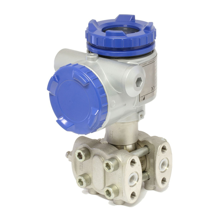
The pressure transmitters of the FCX-AII series measure differential, effective or absolute pressure,
and convert it into a directly proportional output signal of 4 to 20 mA. This transmitter can be
used for the measurement of ow, uid level, density or any other application using the principle
of differential pressure measurement.
The measurement principle of this transmitter is based on the direct conversion of a differential
pressure into a variation of the two capabilities.
The transmitter is compact and lightweight, thus offering a high precision and high reliability.
Local zero setting possible by means of external screw on electronic unit. The smart transmitters
can also be adjusted or congured remotely. For example, the measurement range and the
damping can be congured from the control room using a mobile HHC (hand held communicator).
However, zero adjustment may only be done in nuclear power plants with the aid of an
FXW mobile communicator.
Measurement principle
The operating principle of the differential pressure transmitter is shown in the diagram below.
The differential pressure is applied on the separation membranes and transmitted to the capacitive
micro-pressure transmitter , which converts it into a capacitance difference (MEASURING CELL).
The electronic unit has microprocessor and receives a digital signal from the unit cell that it
converts it to an analogue output signal 4 - 20 mA, and a superimposed digital signal.
The digital signal is compatible with both the Fuji and HART® communications protocols. The
transmitter automatically recognises the protocol used and responds to the connected device
using the appropriate protocol.

10
TN4FCXA2j-EDF-E
Connection terminal block
THE CONSTITUENT ELEMENTS
2
General
Electronic unit
Designation Description
Measuring cell Measures the differential, effective or absolute pressure.
Transmitter set Converts the measurement into a 4/20mA signal.
Bleed valve Allows the measuring chamber to be bled.
(Caution when using it at high pressure.)
Connection mechanism Enables connection to the piping
Electrical connection Inlet of the power supply cable or specic socket for EDF
Zero adjustment Adjusts the zero (see paragraph 7) (Do not use in nuclear power plants)
Designation Description
Connector for the analogue display Used to connect the analogue indicator.
Connector of the digital display Used to connect the digital indicator.
Indicator (option) Gives a local, digital or analogue indication of the output signal.
Symbol Description
+, - Power cable connection
CK+, CK- Used to check the value of the analogue output signal, or to connect an analogue indicator.
Earthing terminal
I
Vent/drain
plug
External adjustment
screw
Detecting unit
Electronics
unit
Process connection
Analog indicator
connector
Digital indicator
connector
Amplifier unit
(Digital) (Analog)
Indicator
%
0
20
40
60
80
100
Terminal unit
CK+
CK–
+
–
FLX
OUT
DISP
ZERO
SPAN
abs
%

11
TN4FCXA2j-EDF-E
Indication of operating mode on the digital indicator
FIX
OUT
DISP
ZERO
abs
%
Display mode
Mode
%
ZERO
DISP
OUT
FIX
abs
–
N
If displayed
Indication in %
External zero setting authorised
Digital display in mode
Output signal in mode
Generation of a constant current
Absolute pressure
Output signal < Zero
If not displayed
Indication in physical size
External zero setting impossible
Digital display in linear mode
Output signal in linear mode
Normal measurement
Relative/ differential pressure
Output signal ≥ Zero
Refreshing of the measure
This is displayed when the unit is for a
gas or steam standardised at conditions
said to be “normal” (101 325 Pa absolute
and 0 or 15 or more rarely 20°C
according to the reference documents).
e.g.: Nm3/h = std cubic meter / hour

12
TN4FCXA2j-EDF-E
INSTALLATION AND CONNECTIONS
3
3.1 Installation
When unpacking, check the transmitter and any accessories.
Before installation, the customer must check the compatibility of the materials in contact with
the process to be measured.
The transmitter can be xed on a 2” mounting tube or against a wall.
The FKE level transmitter is equipped with a ange to connect directly to the ange mechanism.
Note):
In the case of wall mounting, the xing screws (M8) must be provided by the user.
See the “Technical Specications” for blockage of the transmitters.
For a process involving explosive gas, an ADF certied transmitter (explosion
protected) must be tted, otherwise there is a risk of serious accidents
(explosion, re, etc).
DANGER
If the transmitter is not mounted quickly after the delivery, it should preferably
be left in its packaging and stored under normal ambient temperature and
humidity conditions (25°C, 60% HR).
Type of Temperature Temperature Max MWP - Pressure Technical
transmitter Limits Limits measurement Max line specications
Atmospheric Process range (static pressure)
Differential see note* -40 to 120°C 10 mbar -1 to 32 bar
pressure (silicone oil) 60 mbar -1 to 100 bar
320 mbar -1 to 160bar
-20 to +80°C (option: 420 bar) FDSF6-114
(uoridated oil)
1300 mbar -1 to 160bar
(option : 420 bar)
5000 mbar -1 to 160bar
(option : 420 bar)
30000 mbar -1 to 160bar
(option : 300 bar)
Relative see note* -40 to 120°C 1.3 bar, 1.3 bar
pressure (silicone oil) 5 bar 5 bar
30 bar 30 bar FDSF5-80
-20 to +80°C 100 bar 100 bar
(uoridated oil)
500 bar 500 bar
Absolute -25 to 55°C -40 to +85° C 0.16 bar abs 0.64 bar abs
pressure (silicone oil) 1.3 bar abs 1.3 bar abs FDSF5-79
-20 to +80°C 5 bar abs 5 bar abs
(uoridated oil)
30 bar abs 30 bar abs
Level and -25 to 55°C 320 mbar as per PN/lbs FDSF6-03
separators see note* 1300 mbar of separator FDSF7-60
5000 mbar
30000 mbar
INDICATION
*Refer to the “technical specication” for all details regarding the process temperature limits of the transmitters.
For specic transmitters with static pressures > 420 bar, inquire with Fuji Electric France.
Protect the transmitter by a pressure safety element depending on its
application. Install the transmitter at a distance from the measuring point if
the process temperature is too high.
INDICATION

13
TN4FCXA2j-EDF-E
Capteur
Vis
Models FKC, FKG, FKA FKD Models, FKB, FKM
Grower washer
Transmitter
Bracket
Flat washer
Flange mechanisms
M8x12 screw
Grower washer
M8x12 screw
Flat washer
Bracket
Transmitter
On tube
Models FKC, FKG, FKA FKD Models, FKB, FKM
Mount the transmitter on the tube using the U-bracket provided
for this purpose. Apply a tightening torque of approximately
15N.m. The diameter of the tube must be 2” (60.5 mm)
The wall
Secure the bracket to the wall using screws M8
With ange
Introduce the ange of the transmitter to the front of that
of the the piping or the tank mechanism. Fasten them
together with a set of appropriate bolts to the anges used.
Fit the universal bracket on the transmitter as shown below:
The transmitter must be
mounted on its bracket
with the M8 screws, at
washers and Grower
washers provided, maintaining a
screw tightening torque of 15 N.m
for the A4-70 screws.
Mounting the universal bracket
Mounting
• The transmitter is heavy. Handle with caution.
• the installation and connection conditions listed must be observed.
• Improper handling may cause incorrect operation of the transmitter.
• During the installation, ensure that no object likely to cause malfunction or even hazards is
located inside the electronic unit.
• When a device is under voltage in ADF zone:
- Do not change the position of the local indicator.
- Do not change the position of the electronic unit.
• The isolation valves must be selected on the basis of the maximum line pressure. The connection
accessories of the transmitter are provided by the user. If the connections valves and accessories
are under-sized, there is a risk of leakage of hazardous gas or liquid.
• The pipes must be sized according to the process/pressure temperature standards.
• As the membranes are very fragile, please take precautions when handling them.
• Do not bend the capillaries excessively
DANGER
Important

14
TN4FCXA2j-EDF-E
The analogue indicator can be mounted on the electronic side or on the terminal side of the
electrical connection.
The digital indicator can only be mounted on the electronic side.
Follow the instructions below to move the analogue indicator from the electronic side to the terminal
block side.
7/
Connect the red wire (+) of the indicator to
CK+ and the black wire (-) to CK-.
Secure the assembly and ret the cover
for the indicator
4/
Remove the connector of the
indicator on the electronic
side
5/
Fit the assembly cable to the
connector on the indicator
1/
Remove the blind cover on the
terminal side
3/
Ret the blind cover on
the electronic side
2/
Remove the indicator cover on
the electronic side
6/
Install the guide pins
(supplied) on the terminal
Indicator mounted on the
electronic side
Indicator mounted on the terminal side
Indicator mounting position
These manipulations must be avoided in explosion-proof areas.
In nuclear power plants, changes or interventions to the sub-assemblies or
the internal components of the FCX-AII transmitters are prohibited. All changes to
the FCX transmitters-AII delivered must be carried out in the factory after the return
of the hardware to Fuji Electric France.
DANGER
Important

15
TN4FCXA2j-EDF-E
The wiring or the access can be difcult depending on the location of the transmitter, in its original
position. The position of the electronic unit of the transmitter can be changed by rotating it by steps
of 90 or 180 degrees.
Note: Please note the conguration of the electronic unit at the time of its delivery on this unit
before rotating it in order to avoid it turning more than 90°.
The electronic unit is xed using two socket head cap screws (M6 x 12).
Loosen the screws, rotate the assembly either to the left or right by 90°, then retighten the screws.
The analogue or digital indicator can be rotated ±180° by steps of 90°.
Never turn the assembly by more than 90° without
disassembling the exible ribbon cable (risk of
breakage of the exible ribbon cable connecting
the electronics to the measuring cell).
Before any rotation, check that the assembly has
not already been turned (the exible ribbon cable
must NOT be rolled on itself or tight), change the
position of the exible ribbon cable if necessary. To
do this, remove the amplier, undo the connector
for the exible ribbon cable, rotate the electronic
box to the desired position, and ret the assembly.
%
0
20
40
60
80
100
%
0
20
40
60
80
100
%
0
20
40
60
80
100
%
0
20
40
60
80
100
Modication of the position of the electronic unit of the transmitter
These manipulations must be avoided in explosion-proof areas.
Changing the position of the indicator
These manipulations must be avoided in explosion-proof areas.
DANGER
INTERDICTION
DANGER
In nuclear power plants, changes or interventions to the sub-assemblies or the
internal components of the FCX-IIA transmitters are prohibited. All changes to the
FCX transmitters-AII delivered must be carried out in the factory after the return of
the hardware to Fuji Electric France.
Important

16
TN4FCXA2j-EDF-E
Leave a free space of approximately 500 mm around the transmitter in order to facilitate the
adjustments and maintenance.
Connection
mechanism
Slowly unscrew the seat of the bleed screw with a hexagonal
spanner. Remove the damaged Teon tape and ret a new
one (4 to 8 turns).
Ret the bleed valve onto the desired location, by applying a
torque of 25N.m
500 mm
500 mm
Provide enough space around the transmitter
Change in the position of the bleed valves
In nuclear power plants, changes or interventions to the sub-assemblies or the internal
components of the FCX-IIA transmitters are prohibited. Any change in the position
of the bleed valves must be performed in the factory after the return of the hardware
to Fuji Electric France. Any presence of Teon on the nets is strictly prohibited. The
sealing on the nets is performed by Loctite PMUC 5772 PMUC. Loctite PMUC residue on the
nets, after the change of the position of the bleed valves, must be eliminated. The minimum
polymerisation time of this product, before the transmitters are used under pressure, is 24h. The
tightening torque of the bleed valves is 40 N.m.
Important

17
TN4FCXA2j-EDF-E
Connection mechanism
Connecting the transmitter to the pipes.
(1) In general, the pipes are connected to the transmitter via the isolation valves or a manifold.
In this last case, the manifold must be xed to the transmitter with 4 suitable screws (7/16-
20UNF), and the pipes must be connected to the manifold. Apply a tightening torque on
these bolts between 30 and 40 N.m
(2) If not using a valve or manifold, the pipes will be directly linked to the transmitter. If the threads
between the transmitter and the pipes are different, use an oval ange.
Position of the tting mechanism
The element generating the differential pressure must be adapted so that this pressure is correctly
transmitted to the transmitter. The positions of the tting mechanism are determined based on
of the conditions of service (measuring point, process characteristics).
Observe the following mounting positions depending of the process:
Gas measurement Liquid measurement
From 0 to 45° toward the
top relative to the vertical
From 0 to 45° toward the bottom
relative to the horizontal
From 0 to 45° toward the
top relative to the horizontal
Steam measurement
45ϒ
45
ϒ
45
ϒ
45ϒ
45ϒ45
ϒ
TOP TOP
BOTTOM BOTTOM
3.2.1 Differential pressure and ow transmitters (FKC)
Locate the “high” and “low” pressure sides of the transmitter.
The high pressure side is indicated by H and the low pressure side by L on the neck of the cell.
Remove the protective plugs.
The connection mechanisms are protected by the plastic plugs.
Do not forget to remove them before the pipes are connected. Be careful not to damage the
threads or the supports of the seal.
The connection of the pipelines to the transmitter must comply with certain rules to generate a
properly precise measurement:
(1) The transmitter must be installed below the piping for the steam and liquid mechanisms.
(2) The transmitter must be installed above the piping for the gas mechanisms.
The choice of the manifolds in the installation is done according to the maximum
pressure conditions of the process (the accessories such as manifolds and
valves are provided by the user). Process leaks from these components can
distort the measurement.
ATTENTION
Orice plate

18
TN4FCXA2j-EDF-E
%
0
20
40
60
80
100
%
0
20
40
60
80
100
%
0
20
40
60
80
100
%
0
20
40
60
80
100
Connection instructions
1- Measuring gas ow
The transmitter must be installed above the pipes.
If the temperature of the gas is high, condensate
vessels must be used, as with for steam.
4- Measurement of liquid pressure
The transmitter must be installed below the pipes.
3- Measuring steam ow
Two condensate vessels must be installed between
the transmitter and the orice. The pipes connecting
the two condensate vessels in the transmitter must be
lled in advance with water. A bleed must be installed.
2- Measuring liquid ow
The transmitter must be installed below the pipes. The
pipes must be installed so that no gas accumulates
in the transmitter. The installation of a reservoir for
collecting gas can be useful.
Isolating valve
Connection
piping
Piping mechanism
Manifold
Orice plate
Orice plate
Manifold
Condensate
vessel
Connection piping
Piping mechanism
Atmospheric
pressure
Isolating valve
Connection piping
Manifold
Isolating valve Piping mechanism
Pressure reading connector
Piping mechanism
Isolating valve
Connection piping
Manifold

19
TN4FCXA2j-EDF-E
%
0
20
40
60
80
100
%
0
20
40
60
80
100
H1H2
ρ0ρ
h
1
ρ
%
0
20
40
60
80
100
H1
ρ
h
ρ1
(1) When connecting the valves or of manifold, take appropriate protective
measures to avoid the ingress of foreign bodies in the atmospheric release
vents.
(2) When measuring low pressures, it is important to take into consideration
the following points and to limit the effects as much as possible:
• Atmospheric pressure variation due to the wind around the transmitter
• Variation of the ambient temperature in the vicinity of the pressure
take-off pipe.
• Air pressure difference between the pressure take-off pipe and the
location of the transmitter.
To prevent the phenomena cited above, the side atmospheric pressure
connection must be tted with a pressure damper (adjustable to low ow), with
the transmitter possibly mounted in a protection housing, or a compensation
pipe installed on the low pressure side.
High level
Low level
Venting into
atmosphere
5- Measurement of gas pressure
The transmitter must be installed above the pipe to
avoid condensation in the connecting pipes and in
the measurement chambers of the transmitter.
6- Level measurement
(1) Reference column full
The reference column (on take-off pipe at the
top point) must be full of liquid and connected
on the low pressure side of the transmitter. The
take-off pipe at the low point must be connected
on the high pressure side of the transmitter.
Formula for calculating the level:
Zero: ρ.H2 - ρo.H1
Scale (∆P): ρH2 + ρ1h – ρ0H1
ρo, ρ, ρ1: density
H2: low level
H1: high level
h: variation in level
(2) Reference column empty
For an open tank, the low pressure side of the
transmitter must be vented.
Formula for calculating the level:
Zero: ρ.H1
Scale (∆P): ρ.H1 + ρ1.h
ρ, ρ1: density
Condensate
vessel
High level
Low level
Pressure reading
connector
Piping
mechanism
Manifold
Connection piping
Isolating valve
Venting into
atmosphere
Manifold
Manifold
ATTENTION

20
TN4FCXA2j-EDF-E
Precautions for connecting to the piping mechanism
• For liquids, the connecting pipes of the mechanism toward the transmitter must have a minimum
downward slope of 1/10 to avoid gas accumulations.
• For gases, the connecting pipes of the mechanism toward the transmitter must have a minimum
upward slope of 1/10 to avoid liquid or condensate accumulations.
• Do not bend the piping excessively, in order to avoid the accumulation of liquid or gas.
• During the connections, do not submit the pipes to excessive mechanical constraints.
• Use condensate vessels or drains if the pipes could not be tilted.
• The pipes must be selected according to the conditions of use of pressure and temperature.
• When mounting, avoid any mechanical constraints on the take up pipes or take appropriate
measures.
• In the case of external damage (deposit, corrosion, overow, shock etc.) or in case of re, the
transmitters concerned must be checked before commissioning. Avoid external damage to the
transmitter by installing it in a protective casing.
• The transmitter must not be exposed to re. In case of re, the transmitter must be previously
veried before being returned to service. It must not be used if it has been partially or totally
exposed to heat and/ or ames.
• Protection against freezing.
If there is a risk of the uid mechanism freezing, the transmitter and connecting pipes must be
equipped with a heater, as well as a steam or electrical tracer.
Do not exceed the limits of the intended temperatures (measuring cell 120° max, transmitter
85°C).
Even if the installation stops, the heating should be maintained, otherwise the transmitter and
connecting pipes must be drained to prevent freezing.
Table of contents
Other Fuji Electric Transmitter manuals

Fuji Electric
Fuji Electric FCX-AII-V5 series Operating instructions

Fuji Electric
Fuji Electric FCX-AIV Series User manual

Fuji Electric
Fuji Electric FCX Series Quick start guide

Fuji Electric
Fuji Electric FCX-AII Series Operating instructions

Fuji Electric
Fuji Electric FRC User manual

Fuji Electric
Fuji Electric FCX-AII-VG Series User manual

Fuji Electric
Fuji Electric FCX-CII SERIES User manual
Popular Transmitter manuals by other brands

M-system
M-system 6BTS1 instruction manual

GE Security
GE Security S731DV installation instructions

LRS
LRS T9100 user manual

Intelix
Intelix DIGI‐HD‐IR2 installation manual

Becker
Becker Centronic SunWindControl SWC441-II Assembly and operating instructions

Siemens
Siemens SITRANS F MASS 6000 Ex d quick start