manuals.online logo
Brands
  1. Home
  2. •
  3. Brands
  4. •
  5. Fuji Electric
  6. •
  7. Transmitter
  8. •
  9. Fuji Electric FRC User manual

Fuji Electric FRC User manual

FRC
P. 1 / 4TNFFRCDd-E
Fuji Electric France S.A.S.
46, rue Georges Besse - ZI du Brézet - F-63039 Clermont-Ferrand Cedex 2 - France
Tél: +33 4 73 98 26 98 Fax: +33 4 73 98 26 99 http://www.fujielectric.fr
TEMPERATURE TRANSMITTER
(HART communication, intrinsically safe/ameproof) MODEL FRC
SAFE INSTALLATION MANUAL (IECEx / ATEX APPROVAL)
BEFORE USE ....
■SAFETY PRECAUTIONS
This manual describes important points of caution for safe
use of this product in potentially explosive atmosphere.
Please read this manual carefully before installing and op-
erating the product.
■SPECIAL CONDITIONS FOR SAFE USE
• If the model FRC0 is mounted in an area where category 1
equipment is required, precautions have to be taken that
the enclosure can not be charged by static electricity.
• If the model FRC1 is mounted in an area where category
1 equipment is required, it must be installed such that
even in the event of rare incidents, ignition sources due to
impact and friction sparks are excluded.
• When the model FRC0 is installed in environment requir-
ing a higher ingress protection than IP20, it must be ad-
ditionally protected by an enclosure suitable for the envi-
ronment.
■MANUFACTURED DATE CODE IDENTIFICATION
The manufactured year and moth can be identified by the
serial number described on the specification label.
Serial No. Y M xxxxxx
YEAR
B:2021 1 :2041
C:2022 2 :2042
: : : :
U:2022 9 :2049
MONTH
2021 - 2049 (year)
M:January
N:February
P March
: :
Y:December
■MODEL NUMBER IDENTIFICATION
Model No. FRC A
1) ENCOSURE
0 : None (module only)
1 : Yes (die cast aluminium)
2 : Yes (stainless steel casting)
2) SAFETY APPROVAL
A : None
C :
IECEx/ATEX flameproof (for FRC1/FRC2)
E :
ATEX intrinsically safe
3) LCD DISPLAY
0 : None
1 : LCD
4) WIRING CONDUIT
0 : None (for FRC0)
1 : 1/2 NPT
2 : M20 x 1.5
3 : PG 13.5
WARNING
Explosions could result in death or serious injury:
• The enclosure cover must be fully engaged to meet flame-
proof requirements.
• Do not remove the enclosure cover in explosive atmos-
pheres when the circuit is alive (except IS models).
• Do not connect or disconnect the LCD module in explosive
atmosphere when the circuit is alive.
• When the LCD is not installed, covers shall instead be fit-
ted at the open connectors.
• Before you remove the unit or mount it, or before you con-
nect or disconnect the wiring, turn off the power supply
and the input signal for safety. Do not disconnect unless
the area is known to be non-explosive.
• Whenever you need to measure voltage across the termi-
nals or apply a simulated input signal to the terminals,
make sure that there is no danger of explosion in the at-
mosphere.
• Before connecting a HART communicator in an explosive
atmosphere, make sure the instruments in the loop are
installed in accordance with intrinsically safe field wiring
practices.
• Verify the certification of the product described on the
specification label on the product.
• Verify that the operating atmosphere of the transmitter is
consistent with the appropriate hazardous locations certi-
fications.
• Verify that the environmental temperature is within the
temperature class required for the area.
Failure to follow these installation guidelines could result
in death or serious injury:
• Make sure only qualified personnel perform the installa-
tion.
FRC
P. 2 / 4TNFFRCDd-E
Fuji Electric France S.A.S.
46, rue Georges Besse - ZI du Brézet - F-63039 Clermont-Ferrand Cedex 2 - France
Tél: +33 4 73 98 26 98 Fax: +33 4 73 98 26 99 http://www.fujielectric.fr
SAFETY FEATURES & CAUTIONS
■INTRINSICALLY SAFE APPROVAL
• ATEX
EU-
Type Examination Certificate: KEMA 07ATEX0136 X
II 1G Ex ia IIC T4, T5, T6 Ga
Zone 0
EN 60079-0
EN 60079-11
• IS Data
Ui = 30V DC Uo = 6.4V DC
Ii = 96mA DC Io = 30mA DC
Pi = 720mW Po = 48mW
Ci = 0 µF Co = 20 µF
Li = 0 mH Lo = 10 mH
• Prior to installation, check that the safety class of this
unit satisfies the system requirements.
• A safety barrier must be installed between the unit and
its power supply. Refer to “Installation Diagram” attached
at the end of this manual when selecting a safety barrier.
• The power supply and the safety barrier must be located
in a non-hazardous area.
• Environmental temperature must be within the following
ranges depending upon the required temperature class.
T4 : -40°C ≤ Ta ≤ +80°C
T5 : -40°C ≤ Ta ≤ +65°C
T6 : -40°C ≤ Ta ≤ +50°C
• DO NOT RUB the surface of the plastic enclosure with a
dry cloth. Electrostatic charge generated by the friction
may cause an explosion.
• DO NOT APPLY physical impact or friction onto the
FRC1 enclosure.
• Non-metallic materials (window cement) are contained in
the FRC1/FRC2 enclosure and the user must consider the
performance of these materials with respect to chemicals
which may be present in the hazardous area.
• Be sure to secure the terminal cover after wiring (model
FRC0).
• The wiring method must be in accordance with the electri-
cal parameters described in this manual.
• Be sure to earth the unit (model: FRC1/FRC2).
• The intrinsic safety approval of the model FRC1/FRC2 is
applied to the combination of the outdoor enclosure and
the transmitter. The transmitter must not be separated
or replaced.
• Substitution of components may impair suitability for the
hazardous location and may cause an explosion.
• When metal particles are present in the air, install the
model FRC0 inside an outdoor enclosure.
• For installing the FRC0 in an environment with a high
relative humidity exceeding 0 to 95% RH or in a condens-
ing atmosphere, install the unit inside an outdoor enclo-
sure.
■Model FRC1/FRC2 FLAMEPROOF APPROVAL
• IECEx
Certificate of Conformity: IECEx CML 18.0140X
Ex db IIC T4, T5, T6 Gb
IEC 60079-0
IEC 60079-1
• ATEX
EU-
Type Examination Certificate: CML 18ATEX1277X
II 2G Ex db IIC T4, T5, T6 Gb
Zone 1
EN 60079-0
EN 60079-1
• Threaded joint of cover: UN 3 5
/
8- 12
• Engaged threads ≥ 8
• Prior to installation, check that the safety class of this
unit satisfies the system requirements.
• Environmental temperature must be within the following
ranges depending upon the required temperature class.
T4 : -40°C ≤ Ta ≤ +80°C
T5 : -40°C ≤ Ta ≤ +65°C
T6 : -40°C ≤ Ta ≤ +50°C
• Use suitable heat resistant cable and cable glands for am-
bient temperatures ≥ 70°C
• Before wiring, make sure there is no danger of explosion
in the atmosphere.
• Before opening the enclosure, wait at least for 60 seconds
after the power is removed.
• The cable entry device and stopping plugs for unused ap-
ertures shall be of a certified flameproof type, suitable for
the conditions of use and correctly installed.
•
The cable entry conduit is 1/2 NPT or M20 ×1.5 threaded.
• Six or more cable entry threads must be engaged.
• Squeeze the cable entry and stopping plug into the con-
duit with the proper tool.
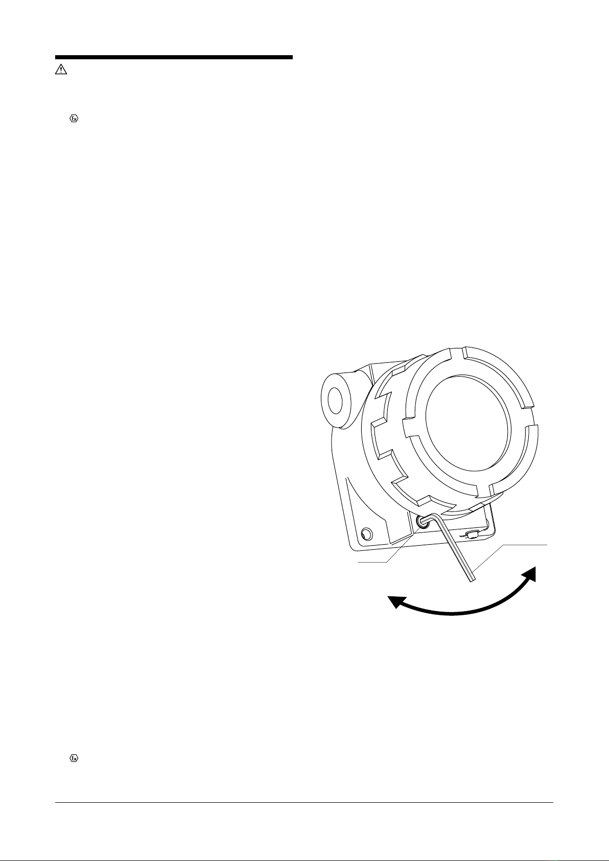
• Before turning the power supply on, be sure to close the
enclosure cover tightly and tighten the fastener as shown
in Figure 1 using a hexagon key wrench. When opening
the enclosure, loosen the fastener first.
Tight
en
Loosen
Fastener
Hexagon Key
Wrench
Figure 1. Enclosure fastener
• DO NOT RUB the surface of the plastic enclosure with a
dry cloth. Electrostatic charge generated by the friction
may cause an explosion.
• Be sure to earth the unit.
• For external earthing or bonding connection a cable lug
shall be used so that the conductor is secured against
loosening and twisting and that contact pressure is main-
tained.
• The flameproof approval of this unit is applied to the com-
bination of the outdoor enclosure and the transmitter.
The transmitter must not be separated or replaced.
• Substitution of components may impair suitability for the
hazardous location and may cause an explosion.
FRC
P. 3 / 4TNFFRCDd-E
Fuji Electric France S.A.S.
46, rue Georges Besse - ZI du Brézet - F-63039 Clermont-Ferrand Cedex 2 - France
Tél: +33 4 73 98 26 98 Fax: +33 4 73 98 26 99 http://www.fujielectric.fr
1
2
3
+
–
+
–
+
–
4
SENSOR
INPUT &
OUTPUT
POWER
SUPPLY
+
–
External Earthing Terminal
Hazardous Location
Zone 0, 1 and 2
Non-Hazardous Location
PS+
PS–
ATEX Approved
Associated Apparatus*1Unspecified
Apparatus *2
ELECTRICAL DATA
Power Supply (+ and –)
Maximum Input Voltage Ui : 30 V
Maximum Input Current Ii : 96 mA
Maximum Input Power Pi : 0.72 W
Maximum Internal Capacitance Ci: 0 μF
Maximum Internal Inductance Li : 0 mH
Sensor Circuit (1 to 4)
Maximum Output Voltage Uo : 6.4 V
Maximum Output Current Io : 30 mA
Maximum Output Power Po : 48 mW
Maximum External Capacitance Co : 20 μF
Maximum External Inductance Lo : 10 mH
NOTES
*1:
*2:
In any safety barrier, the output current of the barrier must be limited
by a resistor ‘R’ such that Io = Uo / R.
The safety barrier must be certified by an EU approved certification body
to Ex ia IIC. (For Zone 1 and 2, Ex ib IIC barriers are also possible and
then the whole loop becomes ‘ib.’)
In case of isolated barrier, the earth is not required.
Apparatus which is unspecified except that it must not be supplied from
nor contain under normal or abnormal conditions a source of potential
with respect to earth in excess of 250 Volts RMS.
Outdoor Enclosure Transmitter
INSTALLATION DIAGRAM for ATEX INTRINSICALLY SAFE MODEL
FRC
P. 4 / 4TNFFRCDd-E
Fuji Electric France S.A.S.
46, rue Georges Besse - ZI du Brézet - F-63039 Clermont-Ferrand Cedex 2 - France
Tél: +33 4 73 98 26 98 Fax: +33 4 73 98 26 99 http://www.fujielectric.fr
1
2
3
+
–
4
SENSOR
INPUT &
OUTPUT
POWER
SUPPLY
+
–
Flameproof Enclosure Transmitter
IECEx/ATEX Flameproof
Sensor Assembly
External Earthing Terminal
Hazardous Location
Zone 1 and 2
Non-Hazardous Location
PS+
PS–
*2
*1
INSTALLATION DIAGRAM for IECEx/ATEX FLAMEPROOF MODEL
ELECTRICAL DATA
Power Supply (+ and –)
Supply Voltage : 12 to 28 V
Output Current : 4 to 20 mA
(Burnout Current : 24 mA)
Sensor Circuit (1 to 4)
Input Signal : 1.0 V max
NOTES
*1:
*2:
*1
Install per local installation codes.
IECEx or ATEX approved cable entries or stopping plugs required.
Sensor assembly must be IECEx or ATEX approved for appropriate hazardous location.

Other Fuji Electric Transmitter manuals

Fuji Electric FCX-AIV Series User manual

Fuji Electric

Fuji Electric FCX-AIV Series User manual

Fuji Electric FCX Series Quick start guide

Fuji Electric

Fuji Electric FCX Series Quick start guide

Fuji Electric FCX-AII-V4 Series Operating instructions

Fuji Electric

Fuji Electric FCX-AII-V4 Series Operating instructions

Fuji Electric FCX-AII Series Operating instructions

Fuji Electric

Fuji Electric FCX-AII Series Operating instructions

Fuji Electric FCX-AII-V5 series Operating instructions

Fuji Electric

Fuji Electric FCX-AII-V5 series Operating instructions

Fuji Electric FCX-AII-VG Series User manual

Fuji Electric

Fuji Electric FCX-AII-VG Series User manual

Fuji Electric FCX-CII SERIES User manual

Fuji Electric

Fuji Electric FCX-CII SERIES User manual

Popular Transmitter manuals by other brands

Shinybow USA SB-6335T instruction manual

Shinybow USA

Shinybow USA SB-6335T instruction manual

Rosemount 8712C product manual

Rosemount

Rosemount 8712C product manual

Carson Reflex Wheel Pro 2 Telemetry 500500038 instruction manual

Carson

Carson Reflex Wheel Pro 2 Telemetry 500500038 instruction manual

Datcon DT1600 U Series operating instructions

Datcon

Datcon DT1600 U Series operating instructions

Phonak Roger inspiro Quick setup guide

Phonak

Phonak Roger inspiro Quick setup guide

Teradek Clip Getting started

Teradek

Teradek Clip Getting started

EnOcean easyfit PTM 250 Installation and operating instructions

EnOcean

EnOcean easyfit PTM 250 Installation and operating instructions

Aplisens APC-2000ALW user manual

Aplisens

Aplisens APC-2000ALW user manual

Gems Sensors UCL-210 Instruction bulletin

Gems Sensors

Gems Sensors UCL-210 Instruction bulletin

Endress+Hauser Proline 500 PROFINET Brief operating instructions

Endress+Hauser

Endress+Hauser Proline 500 PROFINET Brief operating instructions

Visonic MCT-501 installation instructions

Visonic

Visonic MCT-501 installation instructions

RF SOLUTIONS Scorpion quick start guide

RF SOLUTIONS

RF SOLUTIONS Scorpion quick start guide

Mighty Module MM6010 manual

Mighty Module

Mighty Module MM6010 manual

Volfoni ActivHub IR100 user manual

Volfoni

Volfoni ActivHub IR100 user manual

evertz 7700 Series manual

evertz

evertz 7700 Series manual

Analytical Technology Q45R instruction manual

Analytical Technology

Analytical Technology Q45R instruction manual

WIKA T24.10 operating instructions

WIKA

WIKA T24.10 operating instructions

GE SSB Jr. manual

GE

GE SSB Jr. manual

manuals.online logo
manuals.online logoBrands
  • About & Mission
  • Contact us
  • Privacy Policy
  • Terms and Conditions

Copyright 2025 Manuals.Online. All Rights Reserved.