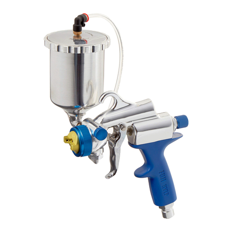
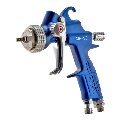
Fuji Spray soloTAN Series User manual

USER
MANUAL
soloTAN™ Series
studioTAN™ Series (formerly miniTAN™)
salonTAN™ Series

1
CONTENTS
Model Details 2
Safety Precautions 3 - 5
Getting Stared 6 - 7
Pars Diagram 8 - 11
Spray Patterns 12 - 13
Spraying Techniques 14
Cleaning and Maintenance 15 - 19
Troubleshooting 20 - 23
Warranty Information 24
CE Declaration Back Cover

2
USER MANUAL
Thank you for purchasing your Fuji Spray® Sunless Spray Tanning
System. This product has been designed to provide an eicient
application of tanning solution products. Please read this user manual
to understand how to operate your Spray Tanning System and you
will be able to accomplish a lawless tan with every application.
The 4200 T-PRO BOTTOM FEED SYSTEM is packaged with:
1) Turbine (soloTAN™, studioTAN™ or salonTAN™) with Power Cord
2) Air Hose
3) T-PRO Bottom Feed Applicator installed with 0.8mm Aircap Set
4) Extra 2 Duck Bills and 1 Pressure Tube
5) User Manual, Cleaning Brush and Wrench
MODEL DETAILS
NOTE: The 4200 T-PRO Applicator is a “Bleeder” style Applicator. This means air will
continuously low out of the front of the Applicator as soon as the Turbine is turned
on, whether you engage the Trigger or not.
The 4000 T-PRO GRAVITY FEED SYSTEM is packaged with:
1) Turbine (soloTAN™, studioTAN™ or salonTAN™) with Power Cord
2) Air Hose
3) T-PRO Gravity Feed Applicator installed with 1.0mm Aircap Set
4) User Manual, Cleaning Brush and Wrench
NOTE: The 4000 T-PRO Applicator is a “Non-Bleed” style Applicator. This means when
the Trigger is not engaged, no air will low through the front of the Applicator. The
spray tan will immediately star when the trigger is engaged.
The TAN7350 BOTTOM FEED SYSTEM is packaged with:
1) Turbine (soloTAN™, studioTAN™ or salonTAN™) with Power Cord
2) Air Hose
3) M-TAN Bottom Feed Applicator installed with 0.8mm Aircap Set
4) User Manual, Cleaning Brush and Wrench
NOTE: The TAN7350 Applicator is a “Bleeder” style Applicator. This means air will
continuously low out of the front of the Applicator as soon as the Turbine is turned on,
whether you engage the Trigger or not.

3
Please read these instructions carefully before using the equipment.
GROUNDING
This appliance must be grounded. If it should malfunction or break
down, grounding provides a path of least resistance for electric
current to reduce the risk of electric shock. This appliance is
equipped with a cord having an equipment-grounding conductor
and grounding plug. The plug must be insered into an appropriate
outlet that is properly installed and grounded in accordance with all
local codes and ordinances.
This appliance is for use on a nominal 120-volt
circuit and has grounding attachment plug that
looks like the plug illustrated. Make sure that the
appliance is connected to an outlet having the
same coniguration as the plug.
Please Note* For UK, Australia, Asia etc. your voltage will be 220-
240v. Check the label on the base of the turbine to ensure your unit
is at the correct voltage for your location.
SAFETY PRECAUTIONS
ELECTRIC SHOCK HAZARD
Improper connection of the equipment grounding conductor can
result in the risk of electric shock.
• Check with a qualiied electrician or service-person if you are in
doubt as to whether the outlet is properly grounded.
• Use only a 3-wire extension cord that has a 3-blade grounding
plug and a 3-slot receptacle that accepts the plug on the product.
• An undersized cord results in a drop in line voltage and loss of
power and overheating.
• Do not modify the plug provided with the appliance. If it will not it
the outlet, have a proper outlet installed by a qualiied electrician.
• To reduce the risk of electric shock or injury, do not expose to rain.
• Never allow unit to freeze.
• Always store the unit inside in a dry location. Store on the loor if in
a basement setting.
• The operator must wear shoes and the loor must not be wet.

4
FIRE AND EXPLOSION HAZARD
Turbine must not be used in an area contaminated by volatile or
lammable materials since sparking can be expected in the normal
operation of the motor. This could ignite the contaminants causing
a dangerous explosion.
• Do not spray lammable or combustible materials near an open
lame or sources of ignition such as cigarettes, motors, and
electrical equipment.
• Keep spray area well-ventilated. Keep a good supply of fresh air
moving through the area. Keep turbine in a well-ventilated area. Do
not spray turbine.
• Do not smoke in the spray area.
• Do not operate light switches, engines, or similar spark producing
products in the spray area.
• Keep area clean and free of lammable materials.
• Fire extinguisher equipment shall be present and working.
• Turn of and disconnect power cord before servicing equipment.
• Ensure ground prongs are intact on sprayer and extension cords.
• Never use 1,1,1-trichloroethane, methylene chloride, other
halogenated hydrocarbon solvents or luids containing such solvents
in equipment with aluminum wetted pars. Such use could result in a
serious chemical reaction, with the possibility of explosion. Consult
your luid suppliers to ensure that the luids being used are
compatible with aluminum pars.
TOXIC FLUID OR FUMES HAZARD
Toxic luids or fumes can cause serious injury or death if splashed in
the eyes or on skin, inhaled, or swallowed.
• Always wear appropriate gloves and eye protection.
• Always wear a mask. Read all instructions of the respirator or
mask to ensure that it will provide the necessary protection against
the inhalation of harmful vapors. Please also check with the local
jurisdiction.
• Tanning Solution and other materials may be harmful if inhaled.

5
EQUIPMENT MISUSE HAZARD
Misuse of equipment can cause serious injury or death.
• Do not operate or spray near children. Keep children away from
equipment at all times.
• Do not overreach or stand on an unstable suppor. Keep efective
footing and balance at all times.
• Stay aler and watch what you are doing.
• Do not operate the unit when fatigued or under the inluence of
drugs or alcohol.
• Do not kink or over-bend the hose.
• Do not use the hose as a strength member to pull or li the
equipment.
• Do not cover turbine case as this will restrict air to the intake and
result to overheating and premature failure of the motor.
• Do not carry turbine while spraying.
• Check the hose, hose connectors and power cord daily. Any worn
or damaged pars should be replaced immediately.
• Use only genuine Fuji Spray replacement pars.
• Never place the Turbine up high, doing so can cause unnecessary
overheating.
• Under no circumstances should you open the Turbine Case. Except
for ilter cleaning or ilter replacement, there is NO maintenance
required for the Turbine unit. If there is any malfunction, unplug the
unit and call us for technical assistance.

6
GETTING STARTED
HOSE CONNECTION
Connect the end of the Hose (female connector) to the Turbine Air
Outlet located on the front of the turbine. This is a simple threaded
connector.
Hand + tight is enough – it is not necessary to use a wrench. This
must not be over tightened.
The Hose is equipped with a brass Quick-Connect
Coupler for easy attachment to the Applicator. To
attach the Applicator to the hose, slide back the
Collar on the brass Quick-Connect Coupler (See
Figure 1).
Inser the Male Fitting at the base of the Handle on
the Applicator into this Quick-Connect and release
the Collar. You should feel the itting click into place.
FIGURE 1
TURBINE
The Turbine has been designed and built with a Breaker Switch. This
essential component will switch the turbine of in the event that there
is overheating or electrical malfunction. To avoid any overheating,
ALWAYS ensure that Filter(s) are in place and clean, and that the Air
Hose is NEVER kinked.
It is normal for the turbine air outlet (manifold) to
become hot during use, please allow your Turbine to
cool for a few minutes before removing the hose from
the turbine manifold.
NOTE: The salonTAN™ Turbine has only one ilter (par # 5029),
studioTAN™ Turbine has two ilters (par # 7224-2), and soloTAN™
has one ilter (par # 7455).
APPLICATOR
To lush out any debris that may have accumulated during assembly or
shipping, we recommend spraying a small quantity of water through
the Applicator. Before tackling any spray tanning, we suggest you
experiment with plain water until you become familiar with all the
controls.

7
GUN HOLDER INSTALLATION
The two holes on the top of the
holder require the black screws
and washers included with this
hardware. These screws it into
Threaded Insers in the Metal
Case. Do not overighten – snug
is ine.
The single Silver-Colored Screw must be installed to the single side
hole of the Gun Holder. Once again, please do not overighten this
screw – snug is ine.
GUN HOLDER USE
Place the Hose Connector #11 (base of the Applicator’s Handle) over
the sha of the Gun Holder shown in above illustration. Please ensure
it is fully set down to the base of the sha. The Applicator will now sit
stationary. The Applicator can be le on the Holder for any length of
time. It is a convenient resting place between spray tans.
studioTAN™ and salonTAN™
soloTAN™
The SoloTAN turbine conveniently has a
built-in gun holder on the top of the machine.
The slot will house the cup with applicator
securely when not in use. Transporing the
turbine unit with applicator in the slot is not
advisable.
Gun Holder

8
T-PRO APPLICATOR
T-PRO APPLICATOR

9
ITEM PART NAME
1 5201 Collar
25302 Aircap
35303 Fluid Nozzle
4 5204 Air Difuser
55205 Air Difuser Seal
65207 Air Divider with Seal (5206)
75221 Fluid Knob
85219 Needle
95220 Needle Spring
10 5225 Fan Pattern Control Knob
11 5229 Hose Connector*
12 5209 Needle Packing
13 5210 Needle Packing Nut
14 5211 Fluid Coupler (4000 T-PRO)*
15 5208 Fluid Coupler (4200 T-PRO)*
16 8088 Cup Lid
17 8181ST Gasket
18 8245T 3oz. Telon Gravity Cup
19 9823DB Cup Assembly
20 2025 Pressure Tube
21 8201ST Lid Gasket
22 5120 Duck Bill
GRAVITY FEED CUP
18
BOTTOM FEED CUP
Pars indicated with * are not removable. T-PRO APPLICATOR
4000 APPLICATOR 4200 APPLICATOR
16
17
19
20
22
21

10
TAN7350 APPLICATOR
TAN7350 APPLICATOR

11
ITEM PART NAME
1 2301 Collar
22302 Aircap
3 2306 Fluid Nozzle
4 2304 90 Degree Nipple*
52303 Difuser
6 2338A Pattern Control Knob*
72307 Fluid Knob
82314 Needle Assembly
9 2309 Needle Spring
10 2310 Handle
11 2311 Hose Connector*
12 2312 Needle Packing*
13 2313 Needle Packing Nut*
14 2330 Trigger Pin*
15 2315 Trigger*
16 2316 Fluid Coupler*
17 9823DB Cup Assembly
18 2025 Pressure Tube
19 8201ST Cup Lid Gasket
20 5120 Duck Bill
Pars indicated with * are not removable.
TAN7350 APPLICATOR
17
18
20
19
BOTTOM FEED CUP
TAN7350 APPLICATOR

12
SPRAY PATTERNS
A B C
A. This pattern is used when spraying from side to side.
B. This pattern is used when spraying up and down.
C. This pattern is used for touch-ups.
In order to set your Applicator to a speciic spray pattern, loosen
the Collar #1, turn the Aircap #2 to the desired position. To lock it in
position, tighten the Collar #1 clockwise until it stops turning. Always
make sure the Collar is snug tight. Do not over-tighten.
On the 4000 and 4200 T-PRO Applicators, the Fan Pattern Control
#10 is located on the front-right side of the Applicator (if looking
from the front). To produce a wide fan pattern, turn Pattern Control
Knob clockwise. For a smaller fan pattern, turn counterclockwise.
Then go into adjusting luid output in tandem.
On the TAN7350 Applicator, the Fan Pattern Control Knob #6 is
located on the rear of the Applicator. To produce a wide fan pattern,
position the Pattern Control Knob verically. For a smaller fan pattern,
position horizontally. Then go into adjusting luid output in tandem.

13
Then turn counter clockwise a little
until a small amount of solution is
released from the Nozzle when you
press the trigger. Once you set the
solution to your liking, you can leave it
in this position.
Always remember that if there is not
enough solution, you can turn the
Fluid Knob counter clockwise for more
output (See Figure 2).
To set the luid output, turn the Fluid Knob #7 clockwise until you
cannot pull the Trigger. DO NOT over-tighten this Fluid Knob as this
will cause damage to the end of the Needle.
FIGURE 2
Rear view of the
T-PRO Applicator
Fluid Control Knob
Setting the Aircap in a verical position – diagram B on page 12
produces a horizontal spray pattern. This pattern is the most useful
and simplest pattern shape for spray tanning. We recommend that
you set and leave the Aircap in this position.
For spray tanning, the general setting is about 4 inches wide from 6
inches distance away. This is a personal preference. If you turn the fan
pattern to a round spray pattern you will have to reduce the amount
of tanning solution by turning the Fluid Knob #7. If you do not do this,
you will get runs. You can use this much smaller pattern to “touch
up” areas such as bikini strap lines or to enhance cerain areas such
as the abdominals. For best results, hold the Applicator closer to your
subject (as close as 1 inch or less).

14
SPRAY TECHNIQUES
When spraying, move the Applicator at a medium, steady speed,
keeping the distance of the Applicator the same throughout the
spray application.
Always keep the solution cup as close to verical as possible. Pointing
the Applicator too far upwards on an angle may cause the liquid to
cease lowing temporarily.
Aer use, never lay the Applicator on its side – liquid will run out
of the gravity cup (for gravity T-PRO model) or pressure tube (for
bottom feed model). Instead, use the gun holder.
If you wish to change the direction of the spray pattern, rotate the
position of the Aircap rather than tilting the Applicator to its side.
CORRECT INCORRECT
Star moving the Applicator in the direction you are going to spray
before pressing the Trigger.
The Trigger must be pulled immediately aer you begin to move. This
is the secret of avoiding runs. Never star spraying without having
your hand in motion. Overlap each successive pass by about one
third the size of the spray pattern (2 inches). This will result in even
coverage.
Always keep Applicator perpendicular to the person you are spraying.
For spray tanning, the horizontal spray pattern will give the best
results, reduce overspray and shoren spraying time. Always use
verical passes to make it easy on your spraying technique.

15
CLEANING AND MAINTENANCE
Tanning solution should not be le in the Applicator’s cup overnight.
It dries and hardens leaving a ilm throughout the luid passages.
Over time, the luid passages can become clogged. To prevent this,
spray soapy water through the Applicator periodically. Always keep
the Applicator clean and dry for next spray. It is imporant to clean
the Applicator daily.
1) Unscrew the lid from the solution cup.
2) Pour any unused Tanning Solution into storage container.
3) Rinse the solution cup and then ill it with clean warm water.
4) Re-attach the lid of the solution cup. Without removing it, turn the
Fluid Knob #7 counter clockwise (this will allow you to pull back the
Trigger all the way).
5) Connect hose to Applicator and switch turbine on.
6) Simply pull the Trigger back and aim the spray of water into a
container, sink or rag. Repeat once more if necessary.
7) Use a wet rag to wipe of any solution on the Applicator or Cup.
8) For the Gravity T-PRO model, the Lid of the solution cup has a
pinhole in the center. Always ensure that the pinhole is open. Clean
this area regularly.
This is all that is needed to keep the Applicator clean and ready for
use. For extra cleaning, add a small drop of dish washing liquid on the
irst lush, but always follow this by lushing with clean water. NEVER
use any abrasive cleaning material like steel wool or any solvent to
clean the Applicator.

16
For a more thorough cleaning, remove the following pars:
• The Air Cap, Fluid Nozzle, Needle, Air Difuser and Air Divider may
be soaked in warm soapy water. Do not use solvents to soak or clean
these components.
• When reinstalling the Air Difuser, carefully rest the Difuser Seal
on the on the back edge of the Difuser, this will ensure that when
installing in place, the alignment is perect.
• There is a Locating Pin on the back side of the Difuser. This pin
must be placed into the matching hole in the Air Divider #6, and into
another matching hole in the Gun Body. The matching hole of the
Gun Body is located at a 12 o’clock position.
NOTE: DO NOT SOAK THE WHOLE APPLICATOR IN ANY LIQUID –
THIS IS NEVER NECESSARY OR ADVISABLE.
• Remove the Fluid Knob #7, Spring #9, and Needle #8 from the rear
of the Applicator.
• At the front of the Applicator, remove Collar #1 and Aircap #2.
• Using the supplied wrench, remove the Fluid Nozzle #3. Once the
Fluid Nozzle is removed, please be careful that the Air Difuser #4 and
Difuser Seal #5 do not fall out of the Applicator. To prevent the air
Difuser and Difuser Seal from falling out when removing the Fluid
Nozzle, have the Applicator pointing upwards.
• Use the Cleaning Brush and warm soapy water to clean behind the
Fluid Nozzle #3.
4000 and 4200 T-PRO Applicators:

17
• Remove the Fluid Knob #7, Spring #9, Needle #8 from the rear of
the Applicator.
• At the front of the Applicator, remove Collar #1 and Aircap #2.
• Using the supplied wrench, remove the Fluid Nozzle #3. Once the
Fluid Nozzle is removed, please be careful that the Air Difuser does
not fall out of the Applicator. To prevent the air Difuser from falling
out when removing the Fluid Nozzle, have the Applicator pointing
upwards.
• Use the Cleaning Brush and warm soapy water to clean behind the
Fluid Nozzle #3.
• The Air Cap, Fluid Nozzle, Needle, Air Difuser and Air Divider may
be soaked in warm soapy water. Do not use solvents to soak or clean
these components.
• When the components are clean, to reinstall the Air Difuser,
carefully rest the Difuser on the front of the Applicator and attach
Fluid Nozzle #3. Use wrench to tighten the Nozzle in place.
• Be sure to install the Needle #8, Spring #9 and Fluid Knob #7 aer
the components of the front of the Applicator are in place.
NOTE: DO NOT SOAK THE WHOLE APPLICATOR IN ANY LIQUID –
THIS IS NEVER NECESSARY OR ADVISABLE.
TAN7350 Applicator:

18
MAINTENANCE OF THE TURBINE
The only maintenance required on the Turbine is the cleaning and
replacing of the Filter(s). The Turbines have either one or two Filters.
Remove based on the instructions below and wash the Filter in warm
soapy water. Dry before replacing back in the Turbine.
Cleaning your ilters regularly is essential to maintaining your Turbine.
It is always a good idea to have a spare pair of ilters on hand.
salonTAN™ Filter
To remove, simply pull the ilter
out from the bottom-right side
of the turbine Case (if looking
from the front). To reuse, wash
the Filter in warm soapy water.
Dry before replacing back in the
Turbine.
salonTAN™ PLATINUM Turbine Filter: #5029
When storing the Turbine, always store the system in
a dry, moisture-free location.
studioTAN™ Filter
To remove, simply pull the
two ilters out from the Filter
Enclosures, one on each side.
To reuse, wash the Filter in
warm soapy water. Dry before
replacing back in the Turbine.
studioTAN™ PLATINUM Turbine
(semi-circle shape ilters): #7224-2

19
soloTAN™ Filter
soloTAN™ PLATINUM Turbine ilter: #7455
1) Pull the grip tabs on both sides of
the grill outwards to release it.
2) Pull the grill directly away from the
main unit to separate.
3) Carefully remove the foam ilter
from the grill.
4) Clean and let dry or replace the
foam ilter, and replace it in the grill.
5) When placing the foam ilter in
the grill, ensure each of the 6 tabs is
helping to hold the foam in place.
6) Make sure the grill is upright, and
place it back on the main unit.
7) Make sure the grill “clicks” back into
place on both sides by pushing it tightly
back on to the unit.
For video instructions, please visit:
www.fujispraysunless.com
This manual suits for next models
3
Table of contents
Other Fuji Spray Paint Sprayer manuals
Popular Paint Sprayer manuals by other brands

new brunswick
new brunswick Innova 43 Operation guide

Cima
Cima PLUS Operation and maintenance instructions

SnowEx
SnowEx Accuspray VSS-2000 Owner's manual and installation instructions

Grace
Grace ULTRA PLUS+ 1000 231-350 A Series Instructions-parts list

MeiVac
MeiVac MAK Series Owner's operation and maintenance manual

Super Handy
Super Handy LFB03 Operator's manual