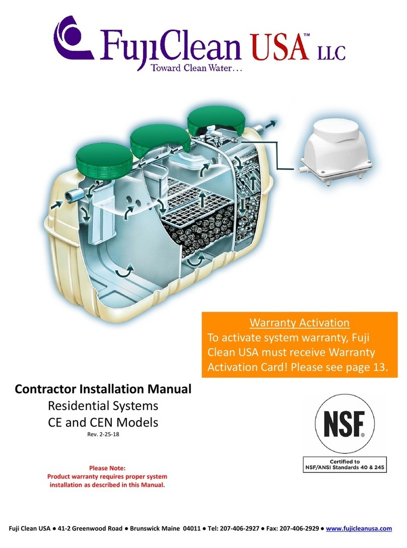
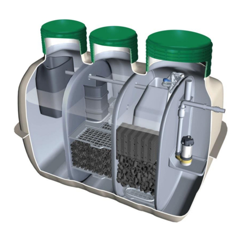
FujiClean ACE User manual

T o w a r d s C l e a n W a t e r
DOMESTIC
T o w a r d s C l e a n W a t e r
DOMESTIC
T o w a r d s C l e a n W a t e r
WASTEWATER
T o w a r d s C l e a n W a t e r
WASTEWATER
WASTEWATER
TREATMENT
F
UJI
TREATMENT
UJI
C
LEAN
Installation
TREATMENT
SYSTEM
LEAN
ACE
Installation
Manual
Updated: 1
Aug
SYSTEM
ACE
Manual
Aug
2020

Thank you for selecting a FujiClean Wastewater Treatment System. Please read this installation
manual carefully before commencing installation.
TABLE OF CONTENTS
1. SAFETY PRECAUTIONS................................................................................................ 1
2. SPECIFICATIONS OF THE SYSTEM............................................................................. 2
3. INSTALLATION ............................................................................................................... 3
4. WIRING INSTRUCTIONS FOR ELECTRICIAN .............................................................. 7
5. COMMISSIONING........................................................................................................... 9
6. WARRANTY & REPAIR POLICY .................................................................................. 10
1 SAFETY PRECAUTIONS
Read the safety precautions carefully before installing the FujiClean plant. The contents of this section are
important to ensure safety. Please pay special attention to the following symbols. Installation must be carried out in
accordance with the relevant safety regulations.
WARNING:
This symbol refers to a hazard or unsafe practice which can result in severe
personal injury or death.
CAUTION:
This symbol refers to a hazard or unsafe practice which can result in personal
injury and/or the potential for product or property damage.
WARNING
Electrical Safety
•All electrical work must be carried out by a licensed electrician.
Excavation Safety
•Before excavation work is carried out, the relevant person or principal contractor for construction work must:
ofind out what underground services exist
oobtain relevant information about the service (location, type, depth, restrictions to be followed);
orecord all relevant information
•All excavation work must be carried out in a safe manner in accordance with the relevant regulations.
Safe Lifting Procedures
•Lifting operation must be carried out in a safe manner in accordance with the relevant regulations.
CAUTION
Access Cover Openings
•Make sure the access covers are securely closed during the installation and operation.
Access Cover Lids
•Make sure there is no vehicular traffic load applied to the access cover lids during the installation and
operation. Do not stand on the access cover lids.
Green Riser Depth
•Maximum depth of cover (riser) is 500mm above the system. Mounting risers exceeding the 500mm height
onto the system would void the warranty.
Above Ground & Half Buried Ground Install
•FujiClean ACE is designed to be installed below ground, as per this installation manual.
•
Do not install this system above ground or half buried above ground without consulting Fuji
Clean Australia for installation instruction.

2
2 SPECIFICATIONS OF THE SYSTEM
SPECIFICATIONS
Volume (L)
Dimensions (mm)
Sedimentation Chamber 1,114
Max. Width 1,440
Anaerobic Filtration Chamber 982
Max. Length 2,510
Aerobic Contact Filtration Chamber 580
Max. Height (with No risers) 1,870
Clarification Chamber
Disnfection/Pump Chamber
281
308
Max. Height (with 300mmH risers)
Max. Height (with 500mmH risers)
2,210
2,360
Total Volume 3,265
Inlet Invert (with No risers) 410
Weight (kg)
440
Inlet Invert (with 300mmH risers)
Inlet Invert (with 500mmH risers)
750
900
Inlet Pipe Nominal Size Dia. 100
Outlet Pipe Nominal Size Dia. 25
*Access cover lids are not included in the height
OS
O S
WL
Inlet Recirculation Pipe
Sedimentation
Chamber
Anaerobic
Filtration
Chamber
Aeration Pipes
Pump Chamber
Chlorinator
Irrigation Pump
Access Covers
Blower Box
Outlet
Riser Ring
Pump
Sedimentation
Chamber
Anaerobic
Filtration
Chamber
Aerobic Contact
Filtration Chamber
Clarification
Chamber
Pump
Chamber
Horizontal Sectional View
Vertical Sectional View
Low Water Level(LWL) ↑
High Water Level(HWL) ↓
Aerobic Contact
Filtration Chamber
Aerobic Contact
Filtration Chamber

3
3 INSTALLATION
STEP 2 EXCAVATION AND BEDDING
•The excavation should allow
approximately 300mm clearance
around the tank.
•Depth of the excavation should be
decided based on the height of the
system, terrain, surface drainage and
the bedding.
•Spread and compact a layer of
bedding sand or crusher dust. It should
be approximately 50-100mm thick
when compacted.
•Ensure the bed is level.
Caution
Warranty will be void if the system is
installed incorrectly.
STEP 3 LIFTING THE PLANT
•Connect a suitable lifting device to the
four lifting points as shown in the
drawing on the right.
Caution
Since the outlet side of the tank is
heavier, adjust the slings or chains so
that the tank can be lifted horizontally.
•Carefully lower the tank into the hole
and place on the bedding sand.
•Tank must be level in all directions to
work properly. The maximum allowable
deviation from level is 1/200.
STEP 1 SITE PREPARATION
•Inspect the tank for any damage during transportation. The air blower, parts bag, and the
submersible pump (if ordered) are stored in the anaerobic filtration chamber.
•The system must be installed away from building foundations and traffic areas so the external
loads will not direct to the system.
Caution Warranty will be void if the system was installed subject to any external loads.
•In the event the system requires repair, please contact Fuji Clean Australia.
Approx. 300 mm clearance
around the tank
Height of the system (with 300mm risers):
2,170 mm
Approx. 50-100 mm thick of
compacted sand layer
30 mm allowance for surface
drainage away from the system
c

4
STEP 4 BACKFILLING – up to the inlet
•The tank is to be filled with water evenly
throughout all chambers before any
backfill is placed around the system.
•Make sure all lids are closed before
backfilling.
•Backfill must not contain any large
stones, rocks or sharp objects and must
be carefully placed around the system.
•Sand or similar material is suitable for
backfilling, no greater than 7mm dia.
•Native soil should not be used when it
consists of heavy clay, since it may
cause subsidence or damage to the
system.
•Backfill must be watered and
compacted.
•Backfill evenly around the system up to
the bottom of the inlet.
STEP 5 CONNECTIONS
Inlet
•100mm dia. pipe into the inlet.
Remove the Blower Box
•Remove the screws securing the blower
box to the adaptor ring (4 places) and
remove the blower box.
Attach the bracket to Blower Box
•Attach the L-shape brackets to blower
box base with screw (4 places).
•These parts are in the parts bag.
Return the Blower Box
•Reposition the Blower Box on top of the
risers and screw the brackets to the
risers (4 places).
•Aline the blower box with the label on the
cover.
•Make sure the top of the base is level.
Watered and compacted
Blower
Box
Screw to the adaptor rings
Secure to the top of riser
Caution: * Neglecting these processes may cause inundation of ground water.
* An out of level base may cause noise issues.
* Mounting risers more than 500mm would void the warranty.
Secure to the blower box base

5
STEP 5 CONNECTIONS (continued)
Blower Pipework
•Connect the blower to the system with
supplied PVC Grey pipes and fittings as
shown in the drawing on the right.
Pump Pipework
•Connect the pump to the outlet with PVC
pressure pipes and fittings
Drill outlet hole
•Drill a hole on the side of the riser (or tank
wall) with 32 or 33 mm hole saw.
•Attach the outlet fitting to the hole.
Conduit for Pump Cable & Float Switch
•The flexible conduit is secured ex-factory so
do not try to pull out from the tank.
•Apply enough silicon sealant on gap
between flexible conduit and the tank to
prevent water and soil from entering the
system.
•The flexible conduit fits the drilled hole tight
on the blower box so no screw or rivet is
needed. We recommend applying silicon
sealant on the gap between the blower box
base and flexible conduit.
Glue into the air intake on the tank.
Connect to the blower
outlet.
Drill a hole with 32 or 33mm
hole saw.
Glue into the
tank outlet.
To the base of the blower box.
To the tank
Screw into the
pump outlet.
Connect each
part with glue.

STEP 7
•
Bottom of the Domed Lid should be
approximately 30mm higher than
ground level so that surface water can
flow away from the system.
STEP 6
•
Run the power cable for the pump and
the cable for the float switch through
th
e
chamber to the blower box.
•
Plug the power cable into
the bottom of the alarm panel.
•
Connect the float switch cable to the
terminal block in the connection box.
•
Pass each cable through the centre of
the Blower box so that it does not touch
the Blower box cover. Interference
between the cable and
vibration and noise.
•
Apply seal plugs and silicone caulking
onto each end of the
Note:
protects the
the blower box from corrosion.
*
Neglecting this process
the warranty.
•
Adjust and lock the height of the float
switch so that the switch is triggered as
soon as the pump fails.
•
Apply silicone caulking at tank wall and
flexible hose.
Note
•
C
with soil so that
are NOT exposed above the
ground.
be protected from UV sunlight.
•
B
subsidence
paint/spray coating on the exposed
riser or add extra soil to completely
cover the riser and tank
STEP 7
BACKFILLING
Bottom of the Domed Lid should be
approximately 30mm higher than
ground level so that surface water can
flow away from the system.
STEP 6
CABLE WORKS
Run the power cable for the pump and
the cable for the float switch through
e
flexible conduit
chamber to the blower box.
Plug the power cable into
the bottom of the alarm panel.
Connect the float switch cable to the
terminal block in the connection box.
Pass each cable through the centre of
the Blower box so that it does not touch
the Blower box cover. Interference
between the cable and
vibration and noise.
Apply seal plugs and silicone caulking
onto each end of the
Note:
This is very important as it
protects the
electrical
the blower box from corrosion.
Caution
Neglecting this process
the warranty.
Adjust and lock the height of the float
switch so that the switch is triggered as
soon as the pump fails.
Apply silicone caulking at tank wall and
flexible hose.
Note
C
ompletely cover the riser and tank
with soil so that
are NOT exposed above the
ground.
The FRP material needs to
be protected from UV sunlight.
B
ackfilled ground level will be
subsidence
.
paint/spray coating on the exposed
riser or add extra soil to completely
cover the riser and tank
BACKFILLING
Bottom of the Domed Lid should be
approximately 30mm higher than
ground level so that surface water can
flow away from the system.
CABLE WORKS
Run the power cable for the pump and
the cable for the float switch through
flexible conduit
from the pump
chamber to the blower box.
Plug the power cable into
the socket on
the bottom of the alarm panel.
Connect the float switch cable to the
terminal block in the connection box.
Pass each cable through the centre of
the Blower box so that it does not touch
the Blower box cover. Interference
between the cable and
cover increase
vibration and noise.
Apply seal plugs and silicone caulking
onto each end of the
flexible conduit
This is very important as it
electrical
components in
the blower box from corrosion.
Neglecting this process
would void
Adjust and lock the height of the float
switch so that the switch is triggered as
soon as the pump fails.
Apply silicone caulking at tank wall and
ompletely cover the riser and tank
with soil so that
the risers and tank
are NOT exposed above the
The FRP material needs to
be protected from UV sunlight.
ackfilled ground level will be
.
Apply the UV
paint/spray coating on the exposed
riser or add extra soil to completely
cover the riser and tank
Bottom of the Domed Lid should be
approximately 30mm higher than
the
ground level so that surface water can
Run the power cable for the pump and
the cable for the float switch through
from the pump
the socket on
the bottom of the alarm panel.
Connect the float switch cable to the
terminal block in the connection box.
Pass each cable through the centre of
the Blower box so that it does not touch
the Blower box cover. Interference
cover increase
Apply seal plugs and silicone caulking
flexible conduit
.
This is very important as it
components in
the blower box from corrosion.
would void
Adjust and lock the height of the float
switch so that the switch is triggered as
Apply silicone caulking at tank wall and
ompletely cover the riser and tank
the risers and tank
are NOT exposed above the
The FRP material needs to
be protected from UV sunlight.
ackfilled ground level will be
Apply the UV
paint/spray coating on the exposed
riser or add extra soil to completely
6
Ground
Level
Approx. 30mm
the socket on
the Blower box so that it does not touch
switch so that the switch is triggered as
Approx. 30mm
Connect the
straight
hose to the pipework.
Riser
Domed Lid
Plug into the bot
Treatment Monitor Unit
Connect to the terminal block in the
Treatment Monitor Unit
straight
rubber
hose to the pipework.
GOOD
Domed Lid
Power cable
for pump
Cable for
float switch
Plug into the bot
tom of the
Treatment Monitor Unit
.
Connect to the terminal block in the
Treatment Monitor Unit
.
Apply seal plugs &
silicone caulking at
outlet on both ends.
Apply silicone
caulking at tank wall
and
flexible hose.
Power cable
for pump
Cable for
float switch
Connect to the terminal block in the
Apply seal plugs &
silicone caulking at
outlet on both ends.
Apply silicone
caulking at tank wall
flexible hose.

7
STEP 9 OWNER’S MANUAL
•Pass a hard copy of the FujiClean ACE owner’s manual supplied with the system (included
in the clear parts bag), or email a soft copy to the owner.
STEP 10 COMMISSIONING FORM
•Commission the FujiClean ACE as instructed on page 9.
•Keep the completed commissioning form for future reference (i.e. warranty claim)
STEP 8 CLOSE THE LIDS
•Close and secure all the three access cover lids with 22 x screws supplied with the system.

4 WIRING INSTRUCTIONS FOR ELECTRICIAN
Power Outlet
All electrical power connections to the system must be carried out by a licensed electrician.
The power supply to the FujiClean ACE is single phase service and requires a dedicated circuit protected by a 10A RCD.
Connect remote alarm plate to the Treatment Monitor Unit with two wire cable. Since the two wire alarm cable is enclosed in the same conduit as the mains supply
to this unit back to the house, the cable must be rated for 240V to comply with the Australian Standard.
Remote Alarm Plate must be positioned inside the dwelling in an area that is readily visible as per the Australian Standard.
If this is not possible an LED strobe light must be placed on blower box which is readily visible from inside the dwelling.
CAUTION: The warranty would void when the above instruction was neglected.
BLOWER
240V / 50Hz
single phase
68W *
*
MAC100RII
Treatment Monitor Unit
High Water Float Switch
to monitor
PUMP FAILURE
Pressure Switch
to monitor
BLOWER FAILURE
Domestic Wastewater Treat ment Systems
MkII TREATMENT MONITOR
WARNING: DO NOT REMOVE C OVER
—
240VAC UNDER
POWER
BLOWER
PUMP
MAXIMUM COMBINED LOAD: 1 0A @ 240Vac (2 400W)
Fault indicator lights
POWER
AIR FAULT
HIGH WATER
AUX ALARM
TREATMENT SYSTEM
240V Mains Power Connection
WARNING!!
Never connect 240 Volt mains power
to the alarm wire connections.
A
B
(Mounted inside
the dwelling)

5 COMMISSIONING
Pre-operational Inspection
Inspect and ensure the following requirements are met:
•The system is accessible and nothing inhibits maintenance.
•Surface water is draining away from the system.
•The system is filled with water, is level, and each component functions properly.
•There is no damage to the tank, piping, or other components.
•There are no air leaks in the air piping and the air piping is connected correctly.
Start Up the System
Step 1.
Make sure electrical power is supplied to the system and all electrical components are plugged in
properly.
Step 2.
Make sure the blower operates properly. To test: turn OFF the air blower for a few moments to
check that the alarm is triggered. Note: As there is a 60 second delay designed into the alarm, it
will take 60 seconds until the air fault alarm is triggered.
Step 3.
Lift up the pump float switch to check that the pump operates properly and lift up the high water
float switch to check that the alarm is triggered. Note: it will also take 60 seconds until the high
water alarm is triggered. Check alarm monitoring unit as well as remote alarm plate for alarm
activation.
Step 4.
Set the Effluent Control Valve to 40, and then make sure that the Effluent Air-lift Pump works
while the water level is above the LWL.
Step 5.
Visually observe the airflow rates on each side of the Aerobic Contact Filtration Chamber to verify
equal flow. If there is an obvious discrepancy in airflow between the two sides, adjust the Aeration
Balance Control Valve so that the airflow is equal.
Step 6.
Step 7.
Measure the recirculation rate at the end of the recirculation pipe while the water level is at the
LWL. The recirculation rate should be approximately 4 to 6 times as much as the inflow rate. If the
daily inflow volume is obtainable, calculate the appropriate recirculation rate accordingly.
Otherwise set the rate to 3 – 5 L/min.
Fill the chlorinator and adjust the dissolve rate if applicable.

10
6 WARRANTY & REPAIR POLICY
Warranty Period
•Structural tank: 15 years from the date of commissioning
•Riser, Blower Box, Access Cover Lids: 2 years from the date of commissioning
•
Electrical components: 2 years
from the date of commissioning
Scope of Warranty
Fuji Clean Australia would repair defects of a FujiClean wastewater treatment system for free of
charge when it was confirmed that the system was installed by a licensed plumbing contractor and
serviced quarterly by an approved FujiClean service agent AND the defects in structure and function
were caused by responsibility of manufacture within the above warranty period.
However the repair would NOT be covered by Fuji Clean Australia when:
consumable parts (i.e. disinfectant, diaphragm assembly, air filter) failed;
there is no service agreement in place between customer and service agent;
the system was not properly installed as per this installation instruction;
the electrical components were not properly wired or mounted as per the Wiring Instruction on
page 8;
the system was broken down or damaged as a result of retrofitting, improper repair, or any other
changes outside the instruction manual.
the damage occurred a result of moving the electrical parts (i.e. air blower);
the damage occurred by heavy loads and vibration of any vehicle;
the damage resulted from natural disasters such as flood, fire, earthquake or lightening,
problems with electrical power such as power surges or incorrect voltages;
the damage resulted from any other accident, inappropriate handling, machine or building
foundation, foreign objects, chemicals.
any trouble caused by excessive amount of inflow and foreign substances as described in the
section 4. Maintenance on page 4;
Contacts
Fuji Clean Australia Pty Ltd.
PO BOX 1230 Oxenford QLD 4210
Ph: 1300 733 619
Website: www.fujiclean.com.au
Email: [email protected]

11
※※※※※※※※※※※※※※※※※※※※※※※※※※※※※※※※
以下は、社外秘につき、取り扱いには十分にご注意ください。
※※※※※※※※※※※※※※※※※※※※※※※※※※※※※※※※
※開発部より、本文書を PDF にしてアウトプットする際には、以下のページは、別ファイルとすること。
※本紙と合わせて、Vドライブ内の所定のフォルダへ保存のこと。
【FujiClean ACE Installation Manual History of Change】
V
er.
D
/M/Y
Page
Detail
1
1
3
0/06/
2
0
20
-
N
ew
12 20/10/2020
6
Added descri tion of cabling in the Blower box.
Change the drawing of the Blower box assembly art. (Change the orientation of
the Treatment monitor unit.)
8
Corrects erroneous descri tions of blower ower consum tion.(69W→68W)
Issue

12
※※※※※※※※※※※※※※※※※※※※※※※※※※※※※※※※
以下は、部内管理用につき、アウトプットしないこと。
※※※※※※※※※※※※※※※※※※※※※※※※※※※※※※※※
【FujiClean ACE Installation Manual 改定履歴】
版 年月日 頁
内容 担当
11 20/06/30 - 新規作成 濵
12 20/10/20
6 ケーブル配線の注記追加、ブロワボックスの図を変更(警報装置
の取り付け向きを変更) 濵
8 ブロワ消費電力の誤記修正(69W→68W) 濵
承認 確認 作成
Table of contents
Other FujiClean Water Filtration System manuals
Popular Water Filtration System manuals by other brands

Noga WaterCare
Noga WaterCare NW 4360 installation instructions

Anest Iwata
Anest Iwata 2Spray FR202 quick start guide

Autotrol
Autotrol LOGIX 255/740 Operation manual

Filtration Group
Filtration Group Silent Care instructions

Walter systemtechnik
Walter systemtechnik WIF-BA-10 operating manual

Danfoss
Danfoss AHF 005 manual

Whirlpool
Whirlpool WHKF-IMTO Installation, use & care guide

Ispring
Ispring WF Series Installation instructions operations manual

Giebel
Giebel VARIO-MA Series manual

DENTSPLY
DENTSPLY Cavitron Touch Maintenance Guide

TWT
TWT IonGuard TWT-5C8-277-0.5 Amp OWNER APPLICATION & INSTALLATION MANUAL

Grohe
Grohe Blue Ultra Pure 33 249 manual