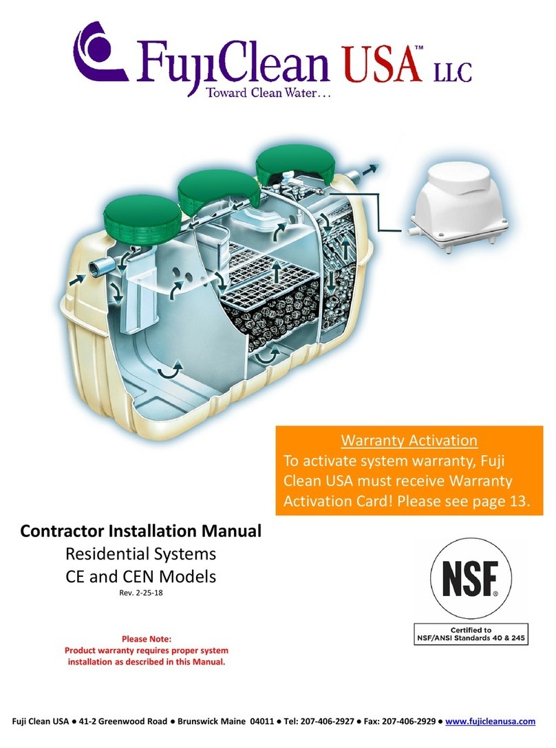
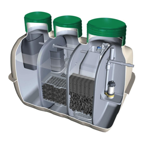
FujiClean CE-4200 Manual

Leaders in environmentally friendly wastewater management
COMMERCIAL WASTEWATER TREATMENT SYSTEM
CE-4200 CE-6000
Operation & Maintenance Manual
FOR SERVICE PERSONNEL ONLY
Updated: 19 January 2015

1
TABLE OF CONTENTS
1SAFETY PRECAUTIONS...............................................................................................................................1
2PROCESS DESCRIPTION ............................................................................................................................2
3MAINTENANCE PROGRAM..........................................................................................................................4
4DESLUDGING................................................................................................................................................9
5TROUBLESHOOTING .................................................................................................................................11
6SPECIFICATIONS .......................................................................................................................................14
1 SAFETY PRECAUTIONS
WARNING
Handling chlorinating agents
There are two main types of chlorinating agents;
oinorganic chlorinating agents such as calcium hypochlorite, lithium hypochlorite, sodium
hypochlorite; and
oorganic chlorinating agents such as trichloroisocyanuric acid, potassium dichloroisocyanurate,
sodium dichlorocyanurate.
Organic and inorganic chlorinating agents are not compatible with each other. Mixing or cross-
contamination of these chemicals can form an explosive mixture.
Chlorinating agents are highly corrosive and very damaging to exposed body tissue. Always wear
protective clothing and protective equipment such as gloves, safety glasses, etc.
Dispose of the material according to manufacturer instructions and according to local regulations.
Read the chemical label before opening the package. Understand the directions for use and safety
information before starting an application.
Working in confined spaces
Personnel required to enter and carry out maintenance work in the unit must comply with confined
space regulations.
Electrical safety
Do not touch any components in the blower box with wet hands.
Read the safety precautions carefully before operating the plant.
The contents of this section are important to ensure safety. Please pay special attention to the following
symbols.
WARNING: This symbol refers to a hazard or unsafe practice which can result in severe
personal injury or death.
CAUTION: This symbol refers to a hazard or unsafe practice which can result in personal
injury and/or the potential for product or property damage.
CAUTION
Preventing overload on the tank
Maintain the area where the system is installed free of all vehicle traffic.
Prevention of public health risk
Do not use treated water for human consumption, livestock watering or irrigating edible crops.

2
2 PROCESS DESCRIPTION
System Components
Sedimentation Chamber
This chamber is designed to physically separate the solids from the incoming water.
Anaerobic Filtration Chamber
This chamber contains a spherical-skeleton type of filter media. Through bacterial growth processes
on the surface of the filter media, biological anaerobic treatment thrives while suspended solids are
captured. The bacteria in this chamber convert nitrates in the recirculated water returning from the
aerobic chamber to gaseous nitrogen. The nitrogen then escapes to the atmosphere.
Aerobic Contact Filtration Chamber
The aeration chamber consists of an aeration upper section with contact media plates and a filter
media lower section. In the upper section, the board contact media adjusts inflow from the anaerobic
filtration chamber and organic matters are decomposed by micro-organism/bacteria on the contact
media surface. Also, organic matters are decomposed by micro-organism/bacteria on the filter media
surface while suspended solids are captured in the lower section. Suspended solids accumulated on
the bottom are constantly transferred to the sedimentation chamber by a recirculation air-lift pump.
Storage Chamber
This chamber is designed to temporarily store the treated water coming out of the aeration chamber.
The treated water is pumped out to the disinfection chamber by an air-lift pump.
Disinfection Chamber
The treated water from the storage chamber passes through the chlorinator for final disinfection. After
disinfection, the treated effluent is stored in the disinfection chamber.

3
Hydraulic Loading and Effluent Quality
CE Commercial System is designed to treat the commercial wastewater from the kitchen, bathroom,
toilet and laundry and capable of producing Advanced Secondary Quality Effluent as specified below.
The daily design flow rate of CE-4200 is 4,200L/day and CE6000 is 6,000L/day.
oBOD equal to or less than 10mg/L
oSuspended Solids equal to or less than 10mg/L
oTotal Nitrogen equal to or less than 20mg/L
oTotal Phosphorus equal to or less than 2mg/L
oThermotolerant coliforms less than 10cfu/100ml
Treatment Flow
Peak-cut System
Despite its compact size, CE Commercial System can effectively cope with shock loading. The
system has a buffer capacity of 252L for CE4200 and 301L for CE6000. The water level in the system
varies whether there is any inflow or not.
When the water level exceeds the Low Water Level (LWL), the treated water is pumped out to the
pump chamber through the chlorinator by the effluent airlift pump. If the water level exceeds the High
Water Level (HWL), the treated water overflows through the effluent weir to the pump chamber. When
there is no inflow, it takes 15 - 30 minutes for the water level to drop from HWL to LWL.
Sedimentation Chamber
Aerobic Contact Filtration Chamber
Storage Chamber
Anaerobic Filtration Chamber
Disinfection Chamber
Influent
Effluent
Air-lift
Overflow
Recirculation
LWL
HWL
LWL
HWL
Air
Effluent Weir
OVERFLOW
To PUMP
CHAMBER
Effluent Airlift Pump

4
3 MAINTENANCE PROGRAM
Scheduled Maintenance
The effective operation of the system is dependent on regular maintenance. The system must be
serviced EVERY 3 MONTHS by a qualified service professional. Regular maintenance involves
periodic removal of excessive sludge and scum build-up from the plant. The frequency of removal
depends on the system’s loading.
Consumable parts for the blower such as air filter and diaphragms need to be replaced as required.
Pre-operational Inspection
Inspect and ensure the following requirements:
The plant is accessible and nothing inhibits maintenance.
Surface water is draining away from the plant.
The plant is filled with water, is level, and each component functions properly.
There is no damage to the tank, piping, or other components.
There are no air leaks in the air piping and the air piping is connected correctly.
Regular Maintenance Procedures
1. Check for the following signs of trouble:
Any obvious signs of physical damage to the plant.
Surface ponding or muddy soil around the plant or disposal area.
Unusual smells around the plant.
2. Open the blower box and inspect all components and vents to ensure they are clean and dry.
3. Make sure the blower operates properly and clean the air filter or replace it, if necessary. Turn off
the blower for a few moments to check that the alarm is triggered.
4. Open all access covers and secure the area around the access openings.
5. Collect a sample of treated effluent from the pump chamber and check the condition.
6. Check if the high water float switch and the pump float switch are operating freely. Lift up the
pump float switch to check that the pump operates properly and lift up the high water float switch
to check that the alarm is triggered.
7. Make sure that the inflow pipe is not blocked and check scum level of each chamber. If any scum
appears in the storage chamber or pump chamber, scoop and transfer it into the sedimentation
chamber.
8. Measure the sludge accumulation depth of each chamber. Any sludge built up in the pump
chamber needs to be transferred to the sedimentation chamber.
9. Agitate the anaerobic media gently to prevent blockage as described in “(1) Degassing / Agitating
Anaerobic Media”on page 8.
10. Measure the recirculation rate as described in “(3) Measuring Recirculation Rate”on page 5.
11. Check if the bubbles are evenly distributed throughout the aeration chamber.
12. Perform a backwash operation as described in “Backwash and Sludge Transfer” on page 6.
13. Check if the effluent airlift pump is operating properly and flush the airlift pump as described in
“Servicing the Effluent Air-lift Pump”on page 7.
14. Adjust the recirculation rate as described in “(2) Adjusting Recirculation Rate” on page 5.

5
15. Refill the chlorinator and adjust the dissolve rate if applicable.
16. Close the blower box and lock all access covers.
Adjusting Valves
(1) Adjusting Aeration Balance
The aeration system is divided into two parts. The airflow balance between right and left part is
adjustable by the Aeration Balance Control Valve, which is normally set to 50. The bubbles should be
evenly distributed throughout the aeration chamber.
Visually observe the airflow rates on each side of the plant to verify equal flow. If there is an obvious
discrepancy in airflow between the two sides, adjust the Aeration Balance Control Valve so that the
airflow is equal.
(2) Adjusting Recirculation Rate
The recirculation rate should be approximately 2 to 4 times as
much as the inflow rate. If the daily inflow volume is obtainable,
calculate the appropriate recirculation rate accordingly. Otherwise
use the table below to set the recirculating rate.
CE4200
CE6000
Recirculation Rate (L/minute)
6.0 - 12
8 - 17
Valve Reading (%)
30 - 35
15 - 20
Important!
Too much recirculation can cause stirring or agitation in the
sedimentation chamber and solids to flow into the anaerobic chamber. Also, treatment performance
could be deteriorated and this could cause odour.
(3) Measuring Recirculation Rate
When measuring the recirculation rate, make sure there is no
inflow to the system and the water level is at Low Water Level
(LWL). If the water level is higher than that, wait until it drops to
LWL. The recirculation rate is increased considerably when the
water level is above LWL.
Although the recirculation rate can be adjusted to some extent by
the Recirculation Control Valve, measure the actual flow rate at
Clos
e
Open
Recirculation Control Valve
Recirculation
Pipe
Indication
Measuring Cup
Barrel Union
Barrel Union
Aeration Valve(blue)
Recirculation Valve(grey)
Effluent Valve(white)
Recirculation Airlift Pipework

6
the end of the recirculation pipe in the Sedimentation Chamber by using a measuring cup.
The upper part of the end of the Recirculation Pipe is cut off as
shown in the drawing on the previous page. Adjust the Recirculation
Control Valve so that the water level in the pipe is between the
horizontal edge of the pipe end and the Indication Line.
If the recirculation rate has increased considerably since the last
maintenance, this could indicate a clogged aeration pipe.
(4) Cleaning Recirculation Air-lift Pump
Excessive biofilm build-up in the recirculation air-lift pump could
affect the recirculation rate. Remove the cap on the air-lift head,
clean inside the pipe with a pipe cleaning brush and water hose.
Backwash and Sludge Transfer
Excessive biofilm growth on the contact and filter media may cause partial clogging or short circuiting
and deteriorate the performance of the system. It is important to carry out a backwash operation and
sludge transfer at every maintenance visit.
Step 1.
Shut off the Effluent Air-lift Pump by turning the Effluent Control Valve (white valve)
clockwise until it won’t turn any more.
Step 2.
Transfer the sludge on the bottom of the aeration chamber by turning the Recirculation
Control Valve (grey valve) to 70 –80 and wait for one minute.
Step 3.
Reset the Recirculation Control Valve (grey valve) to the original position.
Step 4.
Aerate one side of the chamber by turning the Aeration Balance Control Valve (blue
valve) fully one way. Wait for one minute, and then turn the valve fully to the opposite
direction. Wait for another minute, and then reset the valve to the original position.
Step 5.
Repeat Step 2 –4 a few times.
Step 6.
Perform Step 2.
Step 7.
Reset the Recirculation Control Valve (grey valve) and the Effluent Control Valve (white
valve) to the original position. Make sure that the aeration is working properly.
Step 8.
Adjust the recirculation as described in “(2) Adjusting Recirculation Rate”on page 5.
Step 9.
Poke the anaerobic filtration media with a thin pipe (PVC pipe 15mm or smaller diameter
pipe) gently and evenly throughout Anaerobic Filtration Chamber for degassing and
preventing short-circuiting.
Cleaning Aeration Pipes
The following symptoms indicate that the aeration pipes may be partially clogged and the pipes need
to be flushed or cleaned with a pipe brush.
Bubbles are not evenly distributed throughout the chamber even after adjusting the aeration
balance.
Recirculation rate has increased considerably although the recirculation valve setting has not
been changed.
(1) Flushing with Pressure Water
*This method must not be used unless an appropriate backflow prevention device is fitted to the tap.
Step 1.
Close the Recirculation Control Valve (grey valve) and the Effluent Control Valve (white
valve).
Step 2.
Turn off the blower.
Step 3.
Disconnect a barrel union.
Cap (Closure)
Air-lift Head

7
Step 4.
Attach a piece of 13mm PVC pipe to the end of a garden hose with a hose clamp, and
then connect the pipe with the barrel union.
Step 5.
Connect the other end of the hose to a tap and run water through it.
Step 6.
Turn off the tap and disconnect the barrel union.
Step 7.
Connect the hose to the barrel union in the other side of the aeration chamber.
Step 8.
Turn off the tap and reconnect the aeration pipework.
Step 9.
Turn on the blower and adjust all the valve settings.
(2) Cleaning with Pipe Brush
Step 1.
Close the Recirculation Control Valve (grey valve) and the
Effluent Control Valve (white valve).
Step 2.
Turn off the blower.
Step 3.
Disconnect a barrel union.
Step 4.
Insert a pipe cleaning brush into the aeration pipe to clean
it (Wire length of approx 4,500mm is required to reach the
end of the pipe for CE Commercial System).
Step 5.
Reconnect the aeration pipework.
Step 6.
Turn on the blower and adjust all the valve settings.
Servicing the Effluent Air-lift Pump
The Effluent Air-lift Pump can be checked even while the
water level is at the Low Water Level (LWL). Push down
the air-lift pump so that the water flows into the inflow
opening (or pour water directly into the air-lift pump) and
see if the water is discharged to the disinfection chamber.
(1) Setting the Effluent Control Valve
The Effluent Control Valve is initially set to 40% and
there is no need for it to be adjusted normally. However,
if the air-lift pump does not work while the water level
exceeds LWL, the valve needs to be adjusted
accordingly.
Aeration Pipe
Aeration Pipe
Barrel Union
13mm Pipe
Garden Hose
Hose Clamp
Backflow prevention device must
be fitted to the water supply.
Barrel Union
Barrel Union
Aeration Valve(blue)
Recirculation Valve(grey)
Effluent Valve(white)
Recirculation Airlift Pipework
Air Flow
Cap (Closure)
Inflow Opening
Effluent Air-lift Pump
LWL

8
(2) Flushing the Effluent Control Valve
Rotate the valve back and forth from 0 to 100 several times to flush and reset the valve.
Preventing Blockage of Anaerobic Filtration Media
(1) Degassing / Agitating Anaerobic Media
Accumulated sludge on the anaerobic media could
cause a complete or partial blockage.
Agitate the filtration media gently by using PVC or
stainless steel pipe with less than 20mm outside
diameter. Nitrogen gas trapped in the media will be
released during this process.
(2) Backwashing Anaerobic Media
If the anaerobic media is blocked, connect pipe with a blower to backwash the media as shown below.
The end of the pipe should be above the bottom of the media so that the accumulated sludge at the
bottom of the tank is not disturbed.
For your information, the distance from the water level to the bottom of the media is 1,050mm for
CE4200 and 1,250mm for CE6000.

9
4 DESLUDGING
When do you need to pump out the plant?
Desludging is required to remove accumulated solids when one or more of the following conditions
are present:
Biological treatment performance is severely deteriorated due to excessive amounts of oil or
chemicals which interfere with the bacterial activity.
Excessive scum or sludge builds up in the sedimentation chamber.
Abnormal rise of the water level
Excessive scum builds up in the anaerobic filtration chamber and large amounts of solids flow
into the aerobic contact filtration chamber.
Sludge layer at the bottom of the anaerobic filtration chamber builds up to reach the bottom of
the filtration media and the sludge flows into the next chamber.
Excessive suspended solids are observed in the aerobic contact filtration chamber and the
symptoms do not improve even after performing a sludge transfer.
Desludging Procedures
Step 1.
Turn off all electrical components.
Step 2.
Clean the inlet and outlet pipe.
Step 3.
Transfer suspended solids in the aerobic chamber and scum / sludge in the storage
chamber to the sedimentation chamber.
Step 4.
Remove scum and sediment build-up on the filtration media in the anaerobic filtration
chamber.
IMPORTANT!
If sludge in the sedimentation chamber is pumped out before scum / sediment on the
media is removed, scum is drawn into the filtration media as the water level drops.
Outflow openings

10
Step 5.
Insert suction hose into the baffle. Remove sludge from the bottom of the anaerobic
filtration chamber while washing the filtration media and chamber wall with high
pressure water.
Step 6.
Remove scum and sludge in the sedimentation chamber.
Step 7.
(optional)
Although it is unnecessary to vacuum the aerobic contact filtration chamber, it is
possible to do so by inserting the suction hose into the storage chamber and sucking
water from the bottom while washing the media and chamber wall with high pressure
water.
Step 8.
Fill the plant with water to LWL.
Step 9.
Turn on all electrical components.

11
5 TROUBLESHOOTING
Sedimentation Chamber
Symptom
Solution
Inlet pipe is blocked.
Remove the blockage.
Strong and unusual odour
persists even with the manhole
lids closed.
During the first few weeks of operation there may be some
odour from the system. This should cease once the bacteria
are established.
Improper operation may generate odours. Add seeding
material to both anaerobic and aeration chambers, and/or
adjust the operational conditions such as recirculation rate.
Excessive scum accumulations.
(Scum layer reaches the top of
the influent baffle.)
If the depth of sludge accumulation is less than 300mm and
the anaerobic chamber still has the remaining sludge holding
capacity, break the scum layer, otherwise have the plant
pumped out.
Excessive sludge
accumulations.
(Depth of sludge layer exceeds
1,200mm (CE4200) and
1,350mm (CE6000) )
Check the sludge accumulations in the anaerobic chamber. If
the sludge exceeds the holding capacity, have the plant
pumped out.
Foreign materials, excessive oil
or fat entering the system.
Remind the homeowner to refrain from disposing prohibited
substances and limited-use substances.
Anaerobic Filtration Chamber
Symptom
Solution
Excessive scum accumulations.
(less than 100mm)
If the sedimentation chamber still has the remaining sludge
holding capacity, transfer the scum to the sedimentation
chamber, otherwise have the plant pumped out.
Excessive scum accumulations.
(more than 100mm)
Have the plant pumped out.
Excessive sludge
accumulations.
If the bottom sludge layer is thicker than 400mm and
excessive sludge has accumulated on the filtration media,
have the plant pumped out.
Filtration media is blocked up.
(The water level in the anaerobic
chamber is lower than that in the
baffle.)
Perform a degassing operation on the filtration media.
If the problem still persists even after the degassing operation,
backwash the filtration media by using a blower.
Aerobic Contact Filtration Chamber
Symptom
Solution
Bubbles are not evenly
distributed throughout the
chamber or there are no bubbles
at all.
Adjust the aeration control valve.
Check to make sure that there is no leakage from the aeration
pipework.
Check to make sure that the blower operates properly.
Flush the aeration pipe.

12
Perform a backwash operation.
Dissolved Oxygen is less than
1.0mg/L.
Check to make sure that the blower operates properly.
Perform a backwash operation.
Recirculation rate is unable to
be adjusted or no recirculation at
all.
Adjust the recirculation control valve.
Check to make sure that there is no leakage from the aeration
pipework.
Check to make sure that the blower operates properly.
Clean the recirculation airlift pump.
Excessive foaming.
Some foaming may occur during the early stage of operation.
This should cease once the bacteria are established. Seeding
may also be effective.
Excessive suspended solids.
Perform a backwash operation.
Abnormal water level.
(50mm above LWL when there
is no inflow)
Clean the effluent airlift pump and the effluent weir.
Flush the effluent control valve.
If the problem still persists, backwash the filtration media by
using a PVC pipe.
Storage Chamber
Symptom
Solution
Scum forming.
Transfer the scum to the sedimentation chamber.
Excessive sludge
accumulations.
Transfer the sludge to the sedimentation chamber.
Ph is too low or too high.
(Ph < 5.8 or Ph > 8.6)
Check to make sure the recirculation rate is appropriate.
Remind the homeowner not to dispose any prohibited
substances.
Excessive biofilm on the
chamber wall.
Clean the wall and transfer solids to the sedimentation
chamber.
Effluent airlift pump is not
working.
Clean the airlift pump.
Flush the effluent control valve.
Check to make sure there is no leakage from the blower
pipework.
Check to make sure that the blower operates properly.
Effluent weir is blocked.
Remove the blockage.
Pump Chamber
Symptom
Solution
Excessive biofilm on the wall.
(more than 5mm thick)
Clean the wall.
Chlorine tablets dissolve too fast
or too slow.
Adjust the chlorinator.
Poor water clarity with scum or
sediment forming.
Have the plant pumped out.

13
Irrigation pump is not working.
Ensure the power plug is firmly plugged into AC outlet.
Check to make sure the circuit breaker is not tripped.
Check to make sure the pump float switch is not stuck or
entangled.
High water float switch is not
working.
Check wiring connections.
Blower
Symptom
Solution
Blower is not working.
Ensure the power plug is firmly plugged into AC outlet.
Check to make sure the circuit breaker has not tripped.
Send the blower to authorised service personnel.
Air pressure is too low.
Rectify air leaks.
Abnormal noise or vibration.
Ensure the blower is not touching the wall.
Ensure the mounting legs of the blower firmly contact the
base.
Dirty or clogged air filter.
Clean or replace the filter.
In the event that the system requires repair or the components need to be replaced, please contact
Fuji Clean Australia.
FUJI CLEAN AUSTRALIA PTY. LTD.
ABN 74 129 181 317
PO BOX 1230 Oxenford QLD 4870
Ph: 1300 733 619 Fax: 07 5580 0790
www.fujiclean.com.au

14
6 SPECIFICATIONS
TREATMENT UNIT
Horizontal Sectional View
Vertical Sectional View
CE4200
Volume (L)
Dimensions (mm)
Sedimentation Chamber
3,169
Max. Width
1,840
Anaerobic Filtration Chamber
3,177
Max. Length
3,880
Aerobic Contact Filtration Chamber
1,431
Max. Height (No riser)
2,065
Storage Chamber
703
Max. Height (with 300mmH risers)
2,365
Pump Chamber
44
Inlet Invert (No riser)
400
Total Volume
8,524
Inlet Invert (with 300mmH risers)
700
Weight (kg)
530
Inlet Pipe Nominal Size
dia.125
Correspondent Blower Type
MAC150N
Outlet Pipe Nominal Size
dia.125
CE6000
Volume (L)
Dimensions (mm)
Sedimentation Chamber
4,520
Max. Width
1,990
Anaerobic Filtration Chamber
4,511
Max. Length
4,665
Aerobic Contact Filtration Chamber
2,006
Max. Height (No riser)
2,215
Storage Chamber
1,009
Max. Height (with 300mmH risers)
2,515
Pump Chamber
64
Inlet Invert (No riser)
400
Total Volume
12,110
Inlet Invert (with 300mmH risers)
700
Weight (kg)
700
Inlet Pipe Nominal Size
dia.125
Correspondent Blower Type
MAC200N
Outlet Pipe Nominal Size
dia.125
BLOWER
Top View
Side View
Model
MAC150N
MAC200N
Air Flow Volume
150L/min
80L/min
Normal Pressure
18kPa
18kPa
Outlet Pipe Size (diameter)
20mm
20mm
Rated Voltage
AC240V
AC240V
Frequency
50Hz
50Hz
Power Consumption
110W
160W
Weight
9.0kg
9.0kg

15
ALARM SYSTEM
MONITOR UNIT
The monitor unit is installed at the treatment system and provides connections for the
blower, pump and sensors, along with power and signal to the remote alarm. The monitor
unit has three local LED indicators for easy verification of the power input states:
Power: This LED is lit whenever power is present.
High Water: When the High Water alarm is activated this LED will begin to flash. After 1
minute the High Water alarm is sent to the remote alarm panel, at which
time the LED will remain lit.
Air Fault: When the Air Pressure alarm is activated this LED will begin to flash. After 1
minute the Air Fault alarm is sent to the remote alarm panel, at which time
the LED will remain lit.
REMOTE ALARM PANEL
The remote alarm is an electrical switch plate styled unit that informs the owner of the
treatment system to its status at a location remote to the system (i.e. in the house). It uses a
non-polarized 2-wire system to transfer both power and data to the remote alarm unit.
Care must be taken to ensure that the connection between the monitor unit and the remote
alarm are kept tidy and sealed as factors such as moisture and bad connections can cause
erratic behaviour. It is also advised to avoid joins in the cable.
NB: lf the 2-wire alarm cable is to be run in the same conduit as the mains supply to this unit
from the house, the alarm cable must be 240VAC rated. Caution needs to be exercised
when connecting this alarm wiring, as inadvertent connection to the mains voltage will
irreversibly damage both the alarm plate and the control unit.
Muting and Resetting
The mute button can be pressed at any time to stop the remote alarm from beeping. This
mute condition will last for 24 hours (modified from the previous 12 hour setting) before the
mute will expire and the remote alarm will begin beeping again. Note that the mute timeout
period will reset whenever the mute button is pressed so the user can press mute before
going to bed to ensure that it does not wake them during the night.
Once an alarm condition exists, the associated alarm LED will be flashing. Pressing the
"Mute" button will only silence the alarm. If the "Fault" condition still exists then the fault will
continue to be indicated. However, should the fault clear then the alarm condition will
automatically reset and both audible and visual alarms will be cleared.
If at any stage a new alarm condition occurs the mute will also expire and the unit will begin
beeping again.
This manual suits for next models
1
Table of contents
Other FujiClean Water Filtration System manuals
Popular Water Filtration System manuals by other brands

Sigma
Sigma P3 R Instructions for use

Mitte Home
Mitte Home WK 9558 user manual

ADTRAN
ADTRAN Total Access Total Access 19-Inch Fan Filter Installation and maintenance practice

Waterite
Waterite Vectapure II RO-4042H Installation and owner's manual

Marineland
Marineland Penguin Power Filter owner's manual

Philips
Philips GoZero user manual