FOR YOUR SAFETY USE
1:3.1/12.5-400mm 1/1.8” C-Mount
Before using this product, please read this operation manual carefully, and keep the manual handy for future use.
△WARNING and △CAUTION:
△CAUTION
△WARNING
●
●Make sure all parts are mounted and fastened securely.
●
●Do not use the lens to look at the sun or other powerful light sources. Doing so could cause eye injury.
△CAUTION
●
●Before supplying power to the lens, make sure all the parts are connected correctly.
●
●
●
●
Notices
●Do not use this product for purposes beyond the uses mentioned in this manual.
●The lens and its accessories are extremely precise instruments. Never subject them to strong impact.
●The lens may fog when transported from a cool place to one of high temperature and humidity.
To avoid such fogging, before moving the lens allow it to adjust to the ambient temperature of the
environment of use.
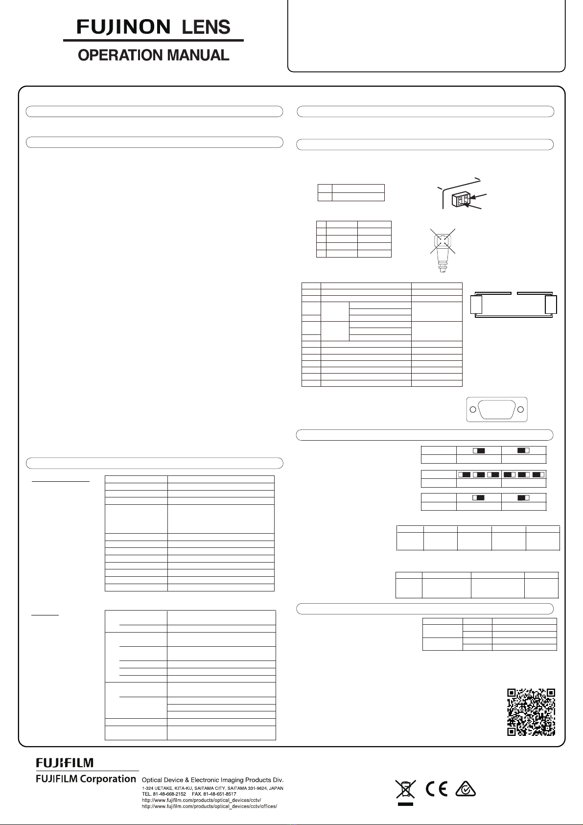
①GENERAL DESCRIPTION ATTACHMENT TO THE CAMERA
④
1) Power Supply Connector (OMRON XW4B-02B1-H1)
2) Iris Connector (EIAJ RC5204 compliant, jack side)
3) Analog Control Connector(OMRON XG4A-1635)
4)
⑦ADJUSTMENT
Application 1/1.8" Format Day/Night Camera
Focal Length 12.5 mm ~ 400 mm
Zoom Ratio 32×
Iris Range F3.1 ~ F16
WIDE 30.90°× 23.54°
TELE 1.03°× 0.77°
Aspect Ratio : 4:3
Field Angle (H×V)
Focus Range ∞ ~ 3 m (from front of lens)
Built-In Filter Visible Light Cut Filter ※
Mount C-Mount
Filter Screw Size M82×0.75 mm
Operating Temperature -10゜C ~ +50゜C
Storage Temperature -20゜C ~ +60゜C
Dimensions(H×V×D) 114mm×108mm×258mm
Mass 2.8 kg Approx
D-sub 9pin Connector(Female)
Protocol C10 or Pelco-D
16-pin Flat Cable Connector
DC 6/9/12V,±6/±9/±12V
Focus DC 6/9/12V,±6/±9/±12V
Optical Filter DC 5~12V
Potentiometer 5±0.5V,3.3±0.3V
4-pin Iris Cable (EIAJ-compliant)
Control Mode DC Iris Control
Video Iris Control
Manual Remote Control
Power Supply Voltage DC 12V
Consumption Approx. 360 mA (operating at maximum)
Approx. 70 mA (at rest)
Serial Control
Connector
Analog Control
Connector
Control Voltage
Zoom
Iris Control
Connector
●
●
●This lens is designed for indoor use. When using the lens outdoors, always take proper measures including
the use of a protective cover.
③SPECIFICATIONS
(1) Optical and Mechanical
(2) Electrical
⑤CONNECTION INTERFACE
①② ③ ④⑤
⑥⑦⑧ ⑨
⑥CONTROL SWITCH SETTINGS
(1) Control mode selection switch settings
(2) Iris mode selection switch settings
(3) Standard power supply selection switch settings
(4)
(5)
Switch lens control between serial mode and
analog mode.
Set iris control to DC iris mode or video iris
mode.
(1) Adjustment of Video Iris
Adjust the video iris LEVEL and ALC using the
respective control trimmers.
(2) Adjustment of Flange Focal Length
If the camera does not have flange focal length adjustment capability, you can adjust the flange focal length
on the lens side.
※
①Loosen the three screws (1.5mm) for securing the flange focal length.
②
③Tighten the fixing screws to secure the flange focal length.
See the documentation for your PC or other control device.
②
㪉
㪋
㪈
㪊
FD32x12.5SR4A-CV1
See the detailed user manual for more information.
The detailed user manual can be downloaded from our website.
URL : https://fm.fujifilm.jp/form/pub/cctvlens/download-e
※ Combining the visible light cut filter with a near-infrared camera is effective for removing dense fog.
△WARNING
This section explains important notices about how to use this product safely. Before using this product, be sure
to read this section carefully and follow the instructions.
The following signs in the text indicate
: Indicates the possibility of causing death or serious injury if the product is misused.
: Indicates the possibility of causing injury or substantial damage if the product is misused.
The FUJINON FD32x12.5 lens is a high-performance, fully HD-compatible zoom lens for 1/1.8" format day/night
cameras.
Do not allow the inside of the product to become wet or moist, as it may cause fire or electric shock. If this
occurs, immediately shut off the power supplied to the lens.
When using a heavy camera, be sure to secure the camera and lens securely to a tripod using the tripod
mounts on both the camera and the lens. Using only the tripod mount on the lens could damage the lens
due to the weight of the camera, or the camera could separate from the mount and fall, causing serious
Do not leave or store the lens in direct sunlight, as the lens may focus light on a nearby object and cause a fire.
Do not aim the lens toward the sun, as the sunlight may focus on the interior of the lens and damage the parts.
Take care when carrying the lens, as dropping it may cause injury.
Make sure the power supplied to the lens is of the rated input voltage; otherwise, a fire, electrical shock or
product damage may occur.
In order to install or release a cable, be sure to hold the joint part. Do not damage the cable by gripping.
It may cause fire or electric shock.
If any sorts of incidents such as unusual smoke, noise, smell or obstacles are found, shut off the power
supplied to the lens and detach the lens from the camera immediately. Please notify the sales agent from
which you purchased the product.
Do not remodel the instrument: it may impair the functions of product or cause electric shock.
Press the threaded portion of the camera mount against the threaded portion of the lens mount, and slowly
rotate the camera clockwise to screw it securely into the lens.
For more information on the arrangement of connectors and switches, see the illustration page.
③
④
⑮
⑯
⑬
⑭
⑪
⑫
⑨
⑩
⑦
⑧
⑤
⑥
①
②
RS-232C Connector (Female)
Same specifications as a typical D-sub 9-pin connector (female).
※Always use the internal power supply for serial control.
Select the external or internal power supply for
the potentiometer.
Serial control mode selection switch
settings
Analog control mode selection switch
settings
Insert an Allen wrench of the appropriate size (2mm) into the hexagonal hole
for flange focal length adjustment, and then turn the adjustment hole to adjust
the flange focal length.
Design and specifications are subject to change without notice.
damage or an accident.
①
②
Bit 1 2-3 4-7 8
Mode ↓:C10
↑:Pelco-D
Pelco-D
Baud rate *1
Pelco-D
Address *2
Pelco-D
Runaway
Protect
SW Position
Mode Serial Analog
SW Position
Mode DC Iris Video Iris
SW Position
Mode Internal External
*1: 00=2400,10=4800,01=9600,11=115200bps
*2: 0000=Address 1 ~ 1111=Address 16
Bit 12-3 4-7
Mode Reserved
Trimmer Name Function Adjustment Direction
Brighter H(clockwise)
LEVEL Darker L(counter-clockwise)
Peak Pk(clockwise)
ALC Average Av(counter-clockwise)
↓:Independent
↑:Common
00/01:12V/±12V
10 : 9V/±9V
11 : 6V/±6V
① Power (DC12V)
②GND
DC Iris Video Iris
1 Brake (-) -
2 Brake (+) -
3 Drive (+) Video Signal
4 Drive (-) GND
Pin Common Mode Independent Mode
1Filter ←
2GND ←
+Wide
3Zoom -Telephoto
4 Common
+Far
5Focus -Near
6Common
7Potentiometer Power Supply (Input) ←
8Potentiometer GND ←
9Focus Potentiometer Output ←
10 Zoom Potentiometer Output ←
11 GND ←
12 Iris Manual Remote (Input) ←
13-16 No connection ←
↑ Wide Angle
↓ Telephoto
↑ Far
↓ Near


