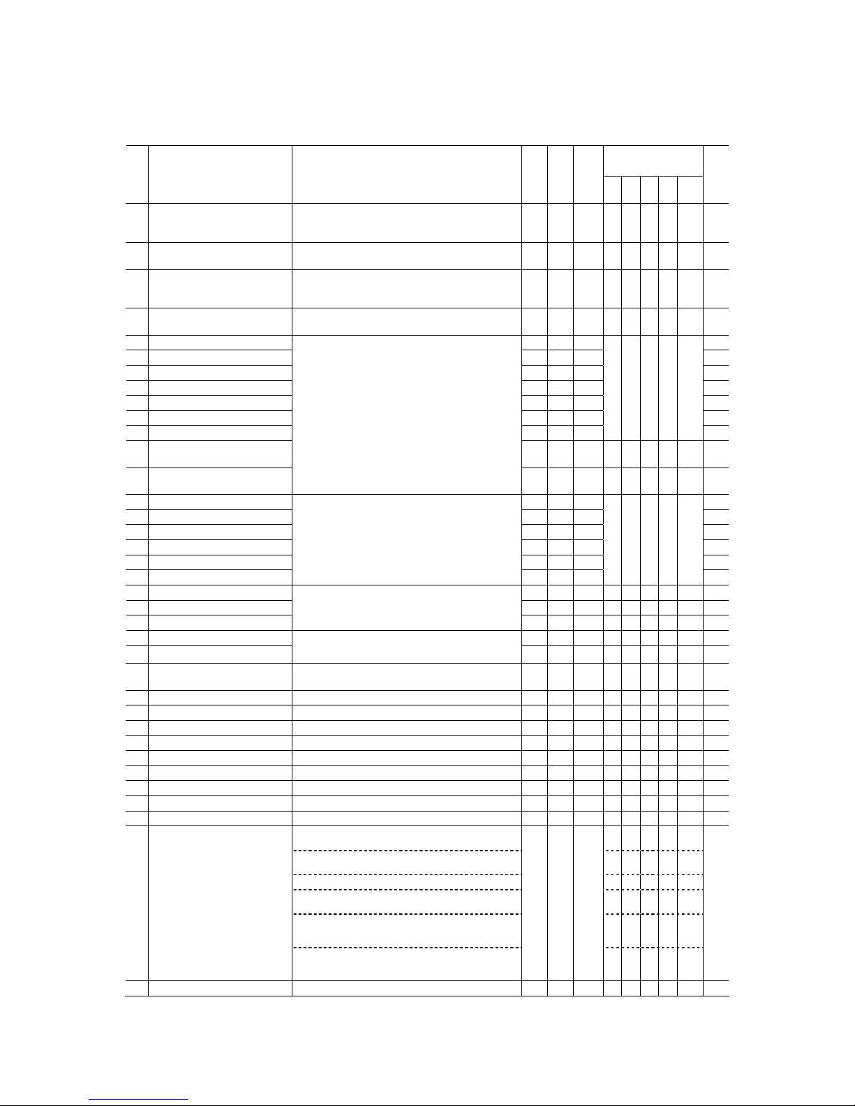
3
Drive control
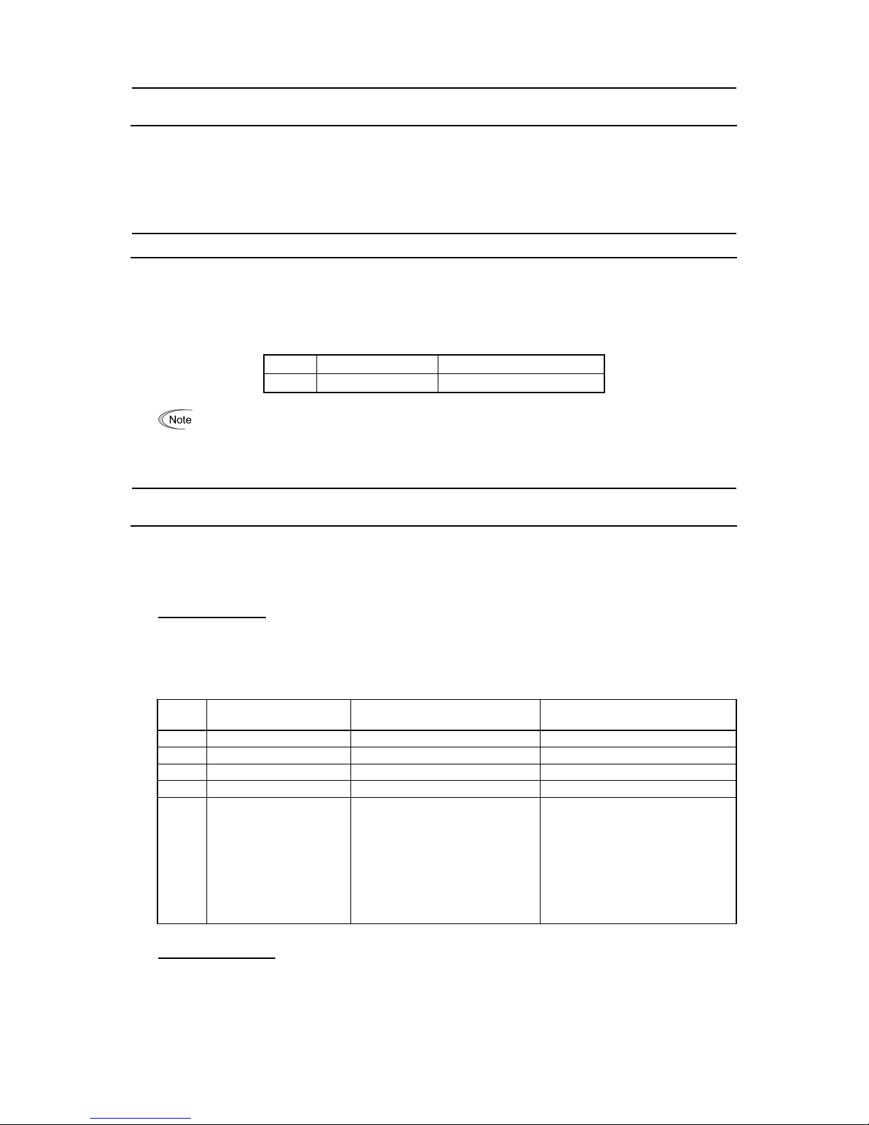
Code Name Data setting range
Change when
running
Data
copying
Default
setting V/f PG
V/f
w/o
PG
w/
PG
Torque
control
Refer
to
page:
d12 Speed Control (Jogging)
I (Integral time)
999: Disable integral action Y Y 0.100 N Y Y Y N 9
d23 PG Error Processing 0: Continue to run 1
1: Stop running with alarm 1
2: Stop running with alarm 2
3: Continue to run 2
4: Stop running with alarm 3
5: Stop running with alarm 4
N Y 2 N Y Y Y N 11
d35 Overspeed Detection Level 0 to 120%
999: Depends on setting of d32 or d33
Y Y 999 N Y Y Y Y 12
d41 Application-defined Control 0: Disable (Ordinary control) N Y 0 Y Y Y Y Y 13
1: Enable (Constant peripheral speed control) N Y N N N
2: Enable (Simultaneous synchronization, without Z phase) N Y N Y N
3: Enable (Standby synchronization) N Y N Y N
4: Enable (Simultaneous synchronization, with Z phase) N Y N Y N
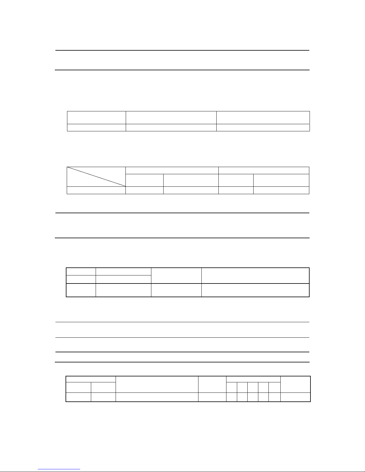
d60 Command
(Encoder pulse resolution)
0014 to 0E10 (hex.)
(20 to 3600 pulses)
N Y 0400
(1024)
N Y N Y N 13
d71 Synchronous Operation
(Main speed regulator gain)
0.00 to 1.50 times Y Y 1.00 N Y N Y N 13
d72 (APR P gain) 0.00 to 200.00 times Y Y 15.00 N Y N Y N 13
d73 (APR positive output limiter) 20 to 200%, 999: No limiter Y Y 999 N Y N Y N 13
d74 (APR negative output limiter) 20 to 200%, 999: No limiter Y Y 999 N Y N Y N 13
d75 (Z phase alignment gain) 0.00 to 10.00 times Y Y 1.00 N Y N Y N 13
d76 (Synchronous offset angle) 0 to 359 degrees Y Y 0 N Y N Y N 13
d77 (Synchronization completion
detection angle)
0 to 100 degrees Y Y 15 N Y N Y N 13
d78 (Excessive deviation detection
range)
0 to 65535 (Display in units of 10 pulses)
(For 10000 or more: Display of the upper four digits in units
of 100 pulses)
Y Y 65535
*4
N Y N Y N 13
d81 Reserved 0 or 1 Y Y 1 - - - - - -
d82 Magnetic Flux Weakening Control
(Vector control without speed
sensor)
0: Disable
1: Enable
Y Y 1 N N N N Y 13
d83 Magnetic Flux Weakening Low
Limiter (Vector control without speed
sensor)
10 to 70% Y Y 40% N N N N Y 13
d84 Reserved 0 to 20 dB Y Y 5 dB - - - - - -
d85 Reserved 0 to 200% Y Y 95% - - - - - -
d90 Magnetic Flux Level during
Deceleration (Vector control)
100 to 300% Y Y 150% N N Y Y N 14
d91 Reserved 0.00 to 2.00, 999 Y Y 999 - - - - - -
d92 Reserved 0.00 to 3.00 Y Y 0.00 - - - - - -
d98 Reserved 0000 to FFFF (hex.) Y Y 0000 Y Y N N N -
d99 0 to 31 Y Y 0 14
Bit 0: Reserved - - - - -
Bit 1: Reserved - - - - -
Bit 2: Reserved - - - - -
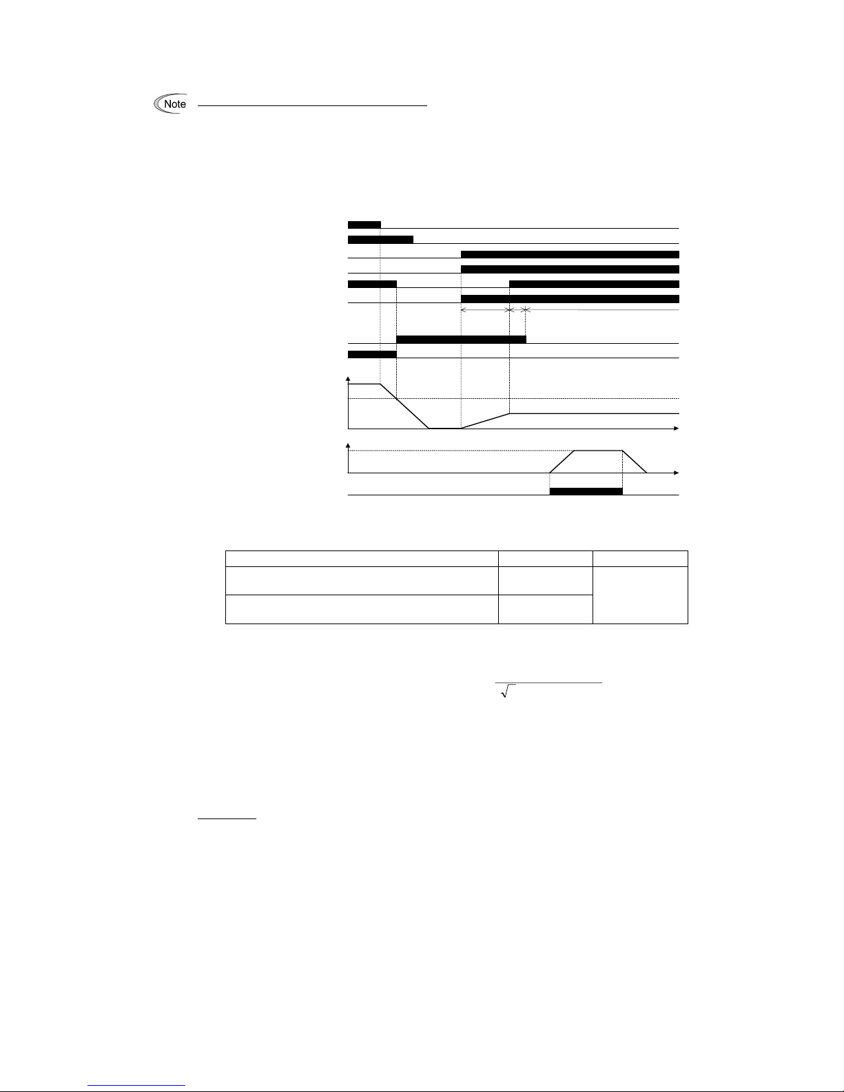
Bit 3: JOG (Ready for jogging) via the communications link
(0: Disable, 1: Enable)
Y Y Y Y N
Function Extension 1
Bit 4: Reserved - - - - -
U01 Customizable Logic: (Input 1) 29 (1029): Synchronization completed (SY) N Y 0 N Y N Y N 8
U02 Step 1 (Input 2) N Y 0 8
U06 Customizable Logic: (Input 1) N Y 0 8
U07 Step 2 (Input 2) N Y 0 8
U11 Customizable Logic: (Input 1) N Y 0 8
U12 Step 3 (Input 2) N Y 0 8
U16 Customizable Logic: (Input 1) N Y 0 8
U17 Step 4 (Input 2) N Y 0 8
U21 Customizable Logic: (Input 1) N Y 0 8
U22 Step 5 (Input 2) N Y 0 8
U26 Customizable Logic: (Input 1) N Y 0 8
U27 Step 6 (Input 2) N Y 0 8
U31 Customizable Logic: (Input 1) N Y 0 8
U32 Step 7 (Input 2) N Y 0 8
*4 The standard keypad displays 6553 on the LED monitor and lights the x10 LED.