FujiFilm FLA-5000 User manual

1
FLUORESCENT IMAGE ANALYZER
FLA-5000
Operation Guide
Science System, Industrial Materials Dept.
Fuji Photo Film Co., Ltd.
Version 1.0 October 2001

2
1Features of the FLA-5000 3
2Turning ON/OFF the FLA-5000 3
3
Startup/Shutdown the FLA-5000 Image Reader
4
4Exposing IPs and Precautions 5
5Reading IP 6
6Reading Fluorescent Samples 9
7Reading Chemiluminescent Samples 16
8Reading digitize Samples 19
Index
Thank you for purchasing our fluorescent image analyzer Model
FLA-5000.
This Operator's Guide is intended to provide a brief description
of the operating procedures for the image analyzer unit incor-
porated into your system together with the functional options
available from the unit. For a detailed description of the opera-
tion of the unit, please refer to the Operating Manual provided.

3
FLA-5000 Operation Guide
1Features of the FLA-5000
* The Fluoro Image Analyzer FLA-5000 employs solid-state lasers of wavelengths suitable for the excita-
tion of fluorescent pigments originally developed by FUJI PHOTO FILM Co., Ltd. It combines several
lasers of different wavelengths with four types of filters and may read gel, membranes, etc. dyed with
various fluorescent pigments. In addition, it may read imaging plates (IPs) originally developed as radia-
tion energy sensors by FUJI PHOTO FILM Co., Ltd.
<Main features>
* Makes high-sensitivity, high-resolution images of gel, membranes, etc. dyed with fluorescent pigments.
* Produces ultra high-resolution images equivalent in the quality to X-ray film;
* Accommodates the IP featuring ultra-high sensitivity, wide dynamic range, reliable linearity, high
resolution and capability of reuse;
* Ensures high resolution, high sharpness and linearity not attainable by existing filmless systems; and
* Obviates the need for a darkroom and automated processing lab for configuration of the system.
2Turning ON/OFF the FLA-5000
1. Press the POWER switch on the right side of the unit to the "I" position.
2. The POWER indicator lamp should light up as shown below to indicate that the unit is correctly
turned ON.
1 Turning on procedures
(It takes 4 to 10 minutes.)
(It takes several to 30 seconds.)
Immediately after turning on power
During self-check or startup adjustment
Ready for operation
2Turningoffprocedures
Check that scanning is not in progress in the unit, then press the POWER switch on the right side of
the unit to the "0" position.
Note: If the alarm buzzer sounds during the power-ON sequence (with the ERROR lamp blinking),
check if the door of the stage setting block is securely closed.

4
3Startup/Shutdown the FLA-5000 Image Reader
1 Startup procedures
1. Turn on the FLA-5000 and peripheral devices.
2. Turn on the computer (DOS/V PC or Macintosh).
3. Make sure that the FLA-5000 has warmed up. (Only the power lamp on the upper left panel on
the front of the FLA-5000 is lit when warming-up is completed.) Start the FLA-5000 Image
Reader from the startup menu or using the shortcut key. (On the Macintosh, double-click the
alias to start the software.)
4. The main window of the FLA-5000 Image Reader is displayed.
IP mode
Click this button to open
the screen for setting the
IP reading conditions.
Fluorescent mode
Click this button to open
the screen for setting
the fluorescent sample
reading conditions.
Chemiluminescence mode
Click this button to open
the screen for setting the
chemiluminescent sample
reading conditions.
Digitize mode
Click this button to open
the screen for setting the
digitize sample reading
conditions.
Use this button to recall
stored reading conditions.
Use this button to change
or register the filter.
Use this button to set the
display menu and file for-
mat.
The conditions of the built-
in laser units are displayed.
This example shows that
three types of laser units
(473 nm, 532 nm and 685
nm) are built in and all units
are ready for operation
(OK).
The number of built-in
photo-multiplier tubes
(PMTs) is displayed.
This example shows that
two PMTs are built in.
The condition of the FLA-
5000 is displayed. This
example shows that the
FLA-5000 is ready for
reading.
2Shutdownprocedures
Click on Exit from the File menu.
(On the Macintosh, click on Quit from the File menu.)

5
FLA-5000 Operation Guide
<Precautions for handling the IP>
1. Keep the IP away from any moisture
Although the IP is designed to be water resistant, moisture makes it susceptible to a lowering of
sensitivity, causing incomplete linearity. Allow the sample to dry out completely before expo
sure.
Tightly wrap any sample that is not dried completely in Saran Wrap to ensure proper moisture
tightness.
2. Keep the IP away from any volatile solvents
Overnight or longer exposure of any sample containing dichloromethane, chloroform, acetone,
acetic acid, or other solvent can cause shrinkage of the protective layer on the surface of the IP,
leading to deformation of the plate. A deformed IP can cause jamming during the scanning.
Wrap such samples with a double layer of Saran Wrap to ensure proper air tightness before
exposure.
3. Wear cotton gloves
When handling the IP, wear cotton gloves to protect the surface of the IP against any contami
nation. When removing the IP from the cassette, use a suction disc. Using the bare hands
(fingernails) can cause the edges to gradually peel off, eventually resulting in an unusable IP
(due to the failure of scanning caused by jamming in the unit).
4. Use a dry cotton cloth for cleaning the IP
Clean the surface of the IP with a dry cotton cloth or other appropriate material. Never use a
water-dampened cloth. For any heavy contamination, use a cloth with a small amount of
anhydrous ethanol (Extra Pure or Guaranteed Reagent). In actuality, however, it is necessary
to ensure that such appropriate anhydrous ethanol to be used has been kept in a brown re
agent bottle or stored in the proper environment recommended by the maker, since any anhy
drous ethanol stored under incorrect storage conditions can cause deterioration of the IP.
5. Keep the IP away from any light source after completion of exposure
After exposure, keep the IP strictly hidden from any direct light source. If the IP is exposed to
light, the image information in the IP may be lost.
4Exposing IPs and Precautions
<Procedures for exposure>
1. Immediately before the start of exposure, complete a thorough erasing process.
2. Wrap the sample in Saran Wrap® or other appropriate wrapping film.
3. Put the sample into the cassette with the surface to be scanned facing up.
For proper position alignment between the sample and the IP, use the grids (inscribed at inter
vals of 25 mm) as a guide.
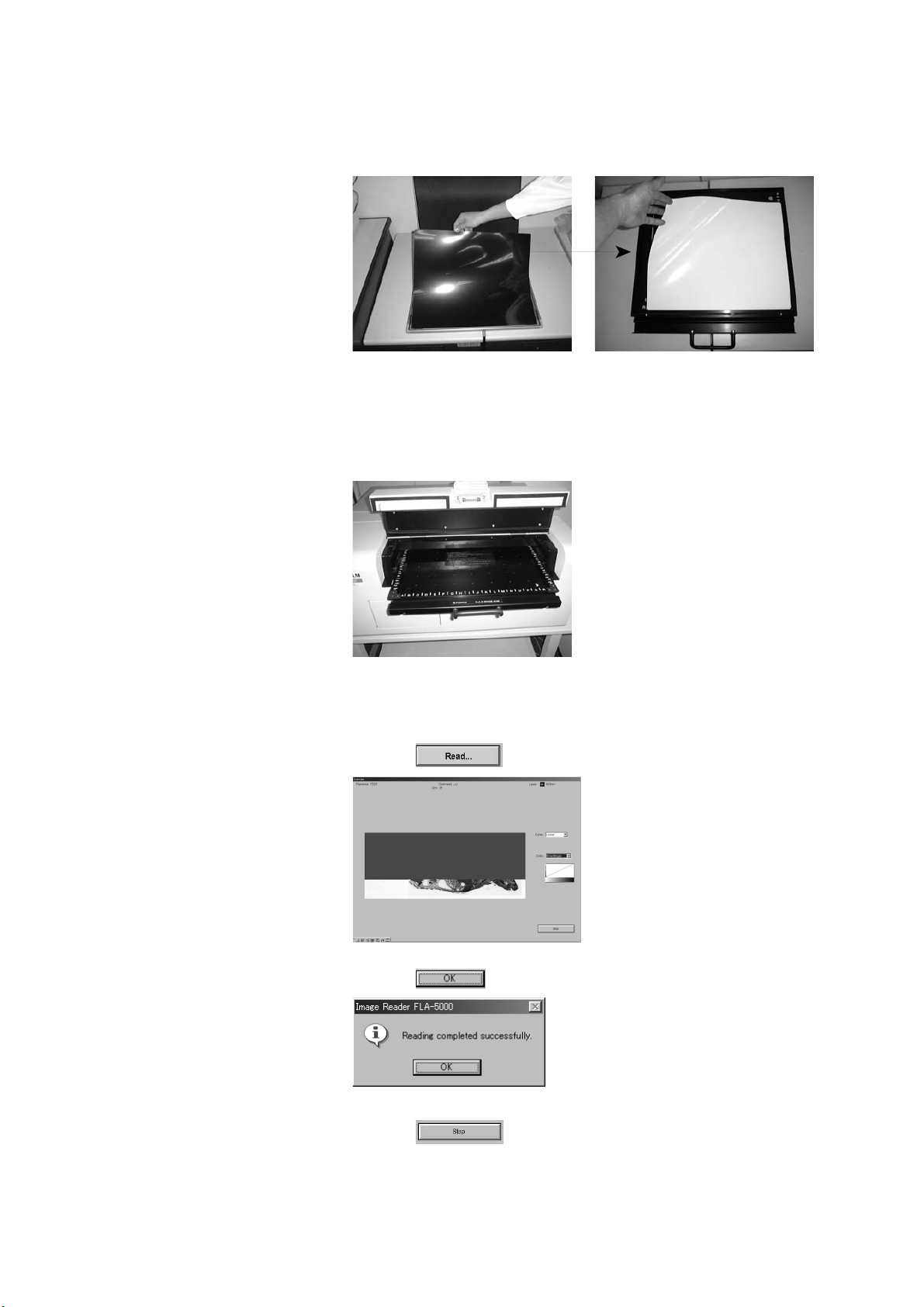
4. Referring to the diagram below, load the IP into the cassette making sure that the surface of the
IP for exposure faces the sample.
Use the notch on the IP as a guide to identify the correct orientation of the sample, the IP and
the loading of the sample-containing IP into the carrier.
5. Close the cassette lid fully until a click is heard.
Adjust the notch of the IP to the left front of the cassette.

6
5Reading IP
1. Turn on the FLA-5000 and peripheral devices.
2. Turn on the computer (DOS/V PC or Macintosh).
3. Make sure that the FLA-5000 has warmed up. (Only the power lamp on the
upper left panel on the front of the FLA-5000 is lit when warming-up is
completed.) Start the FLA-5000 Image Reader from the startup menu
or using the shortcut key. (On the Macintosh, double-click the alias to
start the software.)
4. The main window of the FLA-5000 Image Reader is displayed.
5. Select a reading mode and set the reading conditions.
Set the reading
conditions.
Set an IP on the stage.
Set the stage on the
FLA-5000.
Start reading.
5.1 Selecting a reading mode
Two IP reading modes are available as shown below:
.....This is the standard reading mode, whose reading sensitivity is fixed.
Values of read images are displayed in the PSL/mm2 unit system.
.....The sensitivity of this mode is variable.
Use this mode if you need a low reading sensitivity. Values of read
images are displayed in the LAU/mm2 unit system.
5-1-1 IP S mode
Click the button.
The following window appears.
IP S mode
(1)
(2)
(3)
(4)
(5)
(6)
(7)
(8)
(9)
(10)
(11)
(12)
(13)
(14)
Set the reading conditions by following the instructions shown below.
(1) File Name
Assign a file name to the read image data for
saving.
(2) Comments
Enter any comments required for saving with
the assigned file name.
(3) Change Filter...
Use this button when changing any filter in
formation. (No need to use this option in the
normal IP reading operation.)
(4) Laser
Select the laser to be used. (In the IP
reading mode, the 635nm laser will be
automatically selected.)
(5) Filter
Select the filter to be used for reading. (In
the IP reading mode, the IP filter will be
automatically selected.)
(6) Root Folder Change
Specify where to save the file for saving the
image data.
(7) Gradations
Click to select the number of gradations of
a read image.
(8) Resolution
Click to select the pixel size for reading.
(9) Sample Area
Click to select the method for setting the
reading area.
(10) IP Size
Remember to select the size of the IP when
IP Size has been selected for Sample Area in
(a).
(11) Reading Area
The actual reading area will be shown in the
form of a red-colored box. As neces sary,
move the cursor onto the red frame or to any
point in the red box and drag the box to
change the size and/or position of the reading
area.
(12) Read
Click on this button to start the reading
operation.
(13) Save Template
Use this button to save the reading conditions
in a file. (For details, see the Operation
Manual.)
(14) Return
Click on this button to return to the Main
window.

7
FLA-5000 Operation Guide
5-1-2 IP V mode
Click the button.
The following window appears.
IP V mode
(1)
For the setting of any additional conditions other than those described
below, refer to the instructions for Setting Conditions in the IP S Mode
(page 6).
(1)
This voltage is applied to the first PMT.
Input a voltage value directly in this box. (You may input a value
between 250 and 1000.) The greater the value is, the higher the
voltage to be applied to the PMT and the reading sensitivity are.
Small Value Large
Low Sensitivity High
6. Place the IP on the IP stage.
* You may use only IPs with magnetic absorption layers on the back on the
IP stage. Since an IP is stuck on the IP stage by the magnetic force, any
IPs without magnetic absorption layers may not be attached to the IP stage.
Such IPs are unusable.
6-1 Put the IP cassette with an exposed IP on the side of the IP stage.
6-2 Turn down the room lighting (below 20 luxes).
(Keep the room lighting turned down until the IP stage is set and the
main cover is closed.)

8
6-3 Take the IP out of the IP cassette and set it on the IP stage immediately.
Set the IP on the back side (with a numeric value and alphabetic
characters) of the IP stage so that the IP reading surface (white or
blue side with fluorescent material applied) faces up.
8. Starting reading
8-1 Click the button, and reading starts.
7. Load the IP stage into the FLA-5000 body.
7-1 Open the door of the stage setting block, and set the IP stage with the
stuck IP facedown.
7-2 Push the IP stage to the very end (until it butts).
7-3 Close the door of the stage setting block.
8-2 When reading finishes normally, the following dialog box appears.
Click the button.
8-3 You may finish reading at any time before the whole reading area is read.
Click the button when you want to finish reading.

9
FLA-5000 Operation Guide
6Reading Fluorescent Samples
Set the reading
conditions.
Set a Fluorescent
Samples on the
stage.
Set the stage on the
FLA-5000.
Start reading.
1. Turn on the FLA-5000 and peripheral devices.
2. Turn on the computer (DOS/V PC or Macintosh).
3. Make sure that the FLA-5000 has warmed up. (Only the power lamp on the
upper left panel on the front of the FLA-5000 is lit when warming-up is
completed.) Start the FLA-5000 Image Reader from the startup menu
or using the shortcut key. (On the Macintosh, double-click the alias to
start the software.)
4. The main window of the FLA-5000 Image Reader is displayed.
5. Select a reading mode and set the reading conditions.
5-1 The number of modes available for reading fluorescent samples
depends on the number of photo-multiplier tubes (PMTs) built in the
FLA-5000 as shown below.
One PMT is built in the FLA-5000 Two reading modes are available.
Two PMTs are built in the FLA-5000 Six reading modes are available.
Available when two
PMTs are built in.
Available
when one PMT
is built in.
1 laser 1 image ... One laser is used to excite
fluorescent samples.
Fluorescent light from a sample
passes through a single filter
and forms a single image.
1 laser 1 image Cyclic ... 1-laser, 1-image reading
is repeated (up to four
times).
1 laser 2 image ... One laser is used to excite
fluorescent samples.
Fluorescent light from a sample
is divided and filtrated through
two filters to form two images.
1 laser 2 image Cyclic ... 1-laser, 2-image reading
is repeated (up to two
times).
2 laser 2 image ...
Two lasers a
re used to excite
fluorescent samples simultaneously.
Fluorescent light from a sample is
divided and filtrated through two
filters to form two ima
ges.
2 laser 2 image Cyclic ...2-laser, 2-image reading
is repeated (up to two
times).

10
(1)
(2)
(3)
(4)
(5)
(6)
(7)
(8)
(9)
(10)
(11)
(12)
(13)
(14)
(15)
1l aser 1i mage 1l aser 1i mage Cycl i c
(16)
(17)
1l aser 2i mage 1l aser 2i mage Cycl i c
(18)
(17)
2l aser 2i mage 2l aser 2i mage Cycl i c

11
FLA-5000 Operation Guide
(1) File Name
Assign a file name to the read image data
for saving.
(2) Comments
Enter any comments required for saving
with the assigned file name.
(3) Change Filter...
Use this button when changing any filter
in formation. (No need to use this option
in the normal IP reading operation.)
(4) Laser
Select the laser to be used from the pull-
down menu.
(5)
Enter the voltage value to be applied to
the first PMT. (Voltage values must be an
integer between 250 and 1000.)
(6) Filter
Select the filter to be used for reading.
(7) Root Folder Change
Specify where to save the file for saving
the image data.
(8) Gradations
Click to select the number of gradations
of a read image.
(9) Resolution
Click to select the pixel size for reading.
(10) Sample Area
Click to select the method for setting the
reading area.
(11) Reading Area
The actual reading area will be shown in
the form of a red-colored box.
As necessary, move the cursor onto the
red frame or to any point in the red box
and drag the box to change the size and/
or position of the reading area.
(12) Read
Click on this button to start the reading
operation.
(13) Save Template
Use this button to save the reading
conditions in a file. (For details, see the
Operation Manual.)
(14) Return
Click on this button to return to the Main
window.
(15) Read Cycle (a)
Specify how many times to repeat the
reading cycle. It is possible to repeat
reading up to four (4) times in the “1 laser
1 image Cyclic” mode.
(16)
Voltage to be applied to the
first PMT
Voltage to be applied to the
second PMT
Enter the voltage values. (The voltage
values must be an integer between 250
and 1000.)
(17) Read Cycle (b)
Specify how many times to repeat the
reading cycle. It is possible to repeat
reading up to two (2) times in the “1 laser
2 image Cyclic” or “2 laser 2 image
Cyclic” mode.
(18)
Select the laser to be used from the pull-
down menu.

12
6. Set a fluorescent sample on the fluorescent sample stage or multi-stage.
Setting a gel sample:
6-1 Set a fluorescent gel sample on fluorescent sample stage.
When reading a fluorescent gel sample, set the fluorescent sample
stage on the FLA-5000 first and set the fluorescent gel sample on the
fluorescent sample stage then as shown below. This is an easy way.
6.1.1 Open the door of the stage setting block, and set the fluorescent
sample stage with the printed frame side faceup on the FLA-5000.
6.1.2 Set the gel stopper as shown below.
6.1.3 Put a gel sample so that the side with charging holes faces up.
Fix it with the gel stopper.
Set the stage in the front position.
Do not pull it to the very end.
6.1.4 Press the fluorescent sample stage slowly to the very end (until it
butts).
6.1.5 Close the door of the stage setting block.

13
FLA-5000 Operation Guide
Setting the tighter plates:
6.2 Set a tighter plate on the multi-stage.
6.2.1 Set a tighter plate in any position of the tighter plate frame set on
the multi-stage.
6.2.2 Open the door of the stage setting block, and set the multi-stage
with the printed frame side faceup on the FLA-5000. Push the
multi-stage to the very end.
6.2.3 Close the door of the stage setting block.

14
Setting gel with glass:
6.3 Set a gel sample with glass on the multi-stage.
6.3.1 Detach the tighter plate plug-in as shown below, if it has been set.
6.3.2 Insert one or two gel samples with glass from the front side.
Adjust the movable stays to the glass edges (by moving them from
the back to the front).
6.3.3 Turn the levers on both sides horizontally to lock them.
6.3.4 Fix the glass with two glass holders in the front position and one
glass holder in the rear position. (Turn the dial of each glass holder
clockwise to fix the glass.)
There are spacers on the side of the
glass holders. Each spacer has two
levels. Slide the spacers to adjust the
balance of the glass holders.
Movable stays
6.3.5 Open the door of the stage setting block, and set the multi-stage
with the printed frame side faceup on the FLA-5000. Push the
multi-stage to the very end (until it butts).
6.3.6 Close the door of the stage setting block.

15
FLA-5000 Operation Guide
b) 1-laser, 2-image
Clicking the radio button on the left alter-
nates Overlap and Each.
Overlap display Overlap display
a) 1-laser, 1-image
7. Start reading.
7,1 Click the button, and reading starts.
The condition of the preset reading area, where reading is completed,
is displayed in the reading status real-time display window. Reading
is executed from the front side of the stage to the back. On the monitor
screen, read data is displayed from below to above.
7.2 When reading finishes normally, the following dialog box appears.
Click the button.
7.3 You may finish reading at any time before the whole reading area is read.
Click the button when you want to finish reading.

16
7Reading Chemiluminescent Samples
1. Turn on the FLA-5000 and peripheral devices.
2. Turn on the computer (DOS/V PC or Macintosh).
3. Make sure that the FLA-5000 has warmed up. (Only the power lamp on the
upper left panel on the front of the FLA-5000 is lit when warming-up is
completed.) Start the FLA-5000 Image Reader from the startup menu
or using the shortcut key. (On the Macintosh, double-click the alias to
start the software.)
4. The main window of the FLA-5000 Image Reader is displayed.
5. Setting the reading conditions
5-1 Click the button.
5-2 The following window opens.
Set the reading
conditions.
Set the stage on the
FLA-5000.
Set a Chemilumines-
cent Sample on the
stage.
Start reading.
(1)
(2)
(3)
(4)
(5)
(6)
(7)
(8)
(9)
(10)
(11)
(13)
(12)
Set the reading conditions by following the instructions
shown below.
(1) File Name
Assign a file name to the read image data
for saving.
(2) Comments
Enter any comments required for saving
with the assigned file name.
(3) Change Filter...
Use this button when changing any filter
information. (No need to use this option in
the normal chemiluminescent sample
reading operation.)
(4)
Enter the voltage value to be applied to
the first PMT. (Voltage values must be an
integer between 250 and 1000.)
(5) Filter
Select the filter to be used for reading.
In the chemiluminescent sample reading
mode, no filter is used as a general rule.
In the chemiluminscence mode, the filter
tray must contain at least one through-
position where no filter module is
installed. (For details, refer to the
Operation Manual.)
(6) Root Folder Change
Specify where to save the file for saving
the image data.
(7) Gradations
Click to select the number of gradations
of a read image.
(8) Resolution
Click to select the pixel size for reading.
(9) Sample Area
Click to select the method for setting the
reading area.
(10) Reading Area
The actual reading area will be shown in
the form of a red-colored box.
As necessary, move the cursor onto the
red frame or to any point in the red box
and drag the box to change the size and/
or position of the reading area.
(11) Read
Click on this button to start the reading
operation.
(12) Save Template
Use this button to save the reading
conditions in a file. (For details, see the
Operation Manual.)
(13) Return
Click on this button to return to the Main
window.

17
FLA-5000 Operation Guide
6. Set the fluorescent sample stage on the FLA-5000.
6.1 Open the door of the stage setting block, and set the fluorescent
sample stage with the printed frame side faceup on the FLA-5000.
Set the stage in the front position. Do not pull it
to the very end.
7. Set the chemiluminescent sample on the fluorescent sample stage.
The following descriptions show an example of setting a membrane sample.
7.1 Set a membrane sample with the chemiluminescent side facedown
on the fluorescent sample stage.
Tape the corners of the membrane to
reduce influences of physical
vibrations upon the image.
7.2 Press the fluorescent sample stage slowly to the very end (until it butts).
7-3 Close the door of the stage setting block.

18
8. Starting reading
8.1 Click the button, and reading starts.
8.2 When reading finishes normally, the following dialog box appears.
Click the button.
8.3 You may finish reading at any time before the whole reading area is read.
Click the button when you want to finish reading.

19
FLA-5000 Operation Guide
8Reading Digitize Samples
Set the reading
conditions.
Set the stage on the
FLA-5000.
Set a Digitize Samples
on the stage.
Start reading.
1. Turn on the FLA-5000 and peripheral devices.
2. Turn on the computer (DOS/V PC or Macintosh).
3. Make sure that the FLA-5000 has warmed up. (Only the power lamp on the
upper left panel on the front of the FLA-5000 is lit when warming-up is
completed.) Start the FLA-5000 Image Reader from the startup menu
or using the shortcut key. (On the Macintosh, double-click the alias to
start the software.)
4. The main window of the FLA-5000 Image Reader is displayed.
5. Setting the reading conditions
5.1 Click the button.
5.2 The following window opens.
(1)
(2)
(3)
(5)
(6)
(7)
(8)
(9)
(10)
(11)
(12)
(14)
(4)
(13)Set the reading conditions by following the instructions
shown below.
(1) File Name
Assign a file name to the read image data
for saving.
(2) Comments
Enter any comments required for saving
with the assigned file name.
(3) Change Filter...
Use this button when changing any filter
information. (No need to use this option in
the normal chemiluminescent sample
reading operation.)
(4) Laser
Select a laser unit to be used for reading
from the pull-down menu. (In the digitizing
mode, two options are available, 473nm
and 532nm.)
(5)
Enter the voltage value to be applied to
the first PMT. (Voltage values must be an
integer between 250 and 1000.)
(6) Filter
Click to select the filter to be used for
reading. (In the digitizing mode, two
options are available, Y510 and O575.)
(7) Root Folder Change
Specify where to save the file for saving
the image data.
(8) Gradations
Click to select the number of gradations
of a read image.
(9) Resolution
Click to select the pixel size for reading.
(10) Sample Area
Specify the reading area. (in the digitizing
mode, the available option is Grid.)
(11) Reading Area
The actual reading area will be shown in
the form of a red-colored box.
As necessary, move the cursor onto the
red frame or to any point in the red box
and drag the box to change the size and/
or position of the reading area.
(12) Read
Click on this button to start the reading
operation.
(13) Save Template
Use this button to save the reading
conditions in a file. (For details, see the
Operation Manual.)
(14) Return
Click on this button to return to the Main
window.

20
6. Set the fluorescent sample stage on the FLA-5000.
6.1 Open the door of the stage setting block, and set the fluorescent
sample stage with the printed frame side faceup on the FLA-5000.
Set the stage in the front position. Do not
pull it to the very end.
7. Set the fluorescent sample stage on the FLA-5000.
7.1 Set a sample with the migration side facedown on the fluorescent
sample stage.
7.2 Put the fluorescent plate for digitizing supplied with the fluorescent
sample stage on the digitize sample.
* Put the fluorescent plate with the mat (lusterless) side facedown.
7.3 Press the fluorescent sample stage slowly to the very end (until it butts).
7-4 Close the door of the stage setting block.
Table of contents
Other FujiFilm Measuring Instrument manuals
Popular Measuring Instrument manuals by other brands

IFM Electronic
IFM Electronic SI0562 operating instructions

Kusam-meco
Kusam-meco KM 907 Operation manual

Hioki
Hioki CT6845-05 instruction manual

ProMinent
ProMinent DULCODOS DSWb SP10 Assembly and operating instructions

Novus
Novus NVR-6332-H8/FR user manual

Anaheim Automation
Anaheim Automation H300 instruction manual