2
Safety Precautions
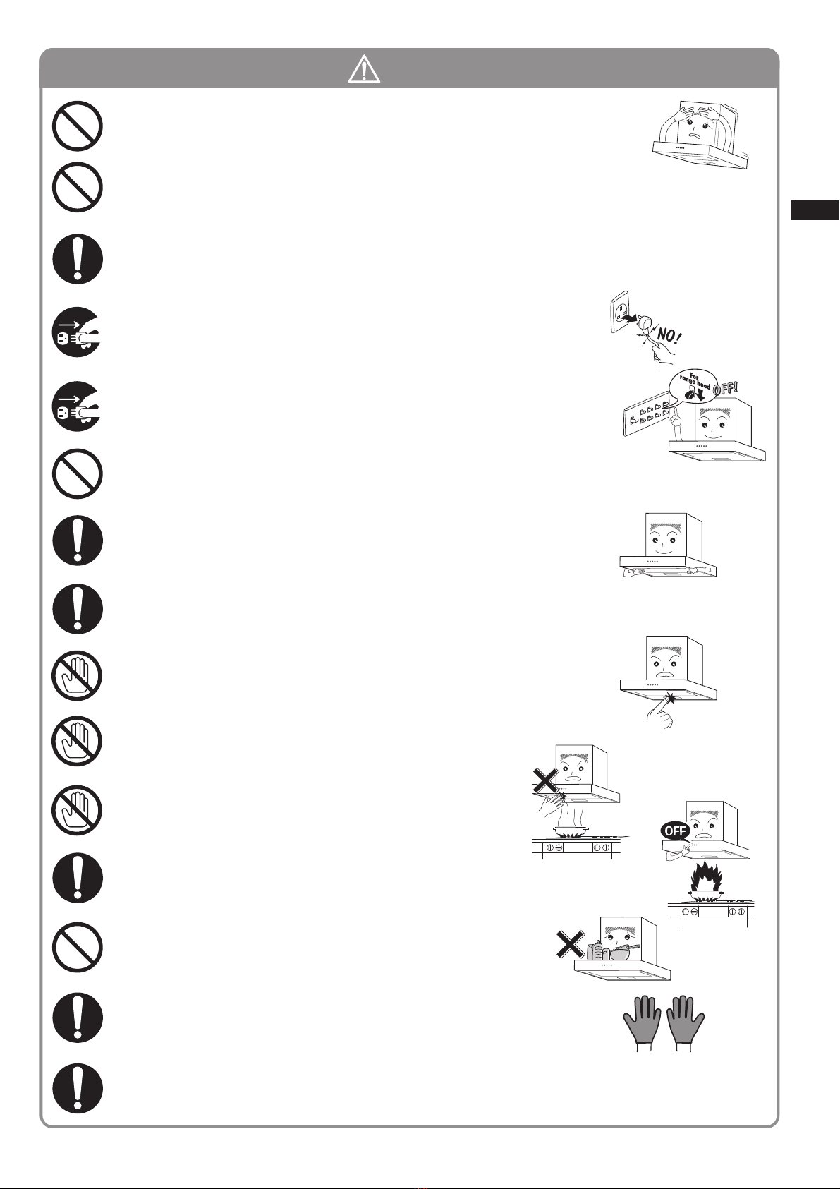
Be sure to disconnect the power plug from the
wall outlet, or switch off the breaker when care
and maintenance. Also, don’t handle the power
plug or breaker with wet hand.
Electric shock or injury may result in.
Disconnect
the plug
Breaker
Never attempt to disassemble, repair, or modify.
Entrust them to the qualified technician, otherwise fire,
electric shock, or abnormal performance may occur.
Don’t connect to the power voltage other than 220V/230V/240V AC.
Fire or electric shock may result in.
When passing a metal duct through the wall composed of metal lath,
wire lath, or metal board, be careful not to touch these parts electrically.
Fire or electric shock may result in if leakage current flows.
Disassembly,
repair, or
modification
prohibited
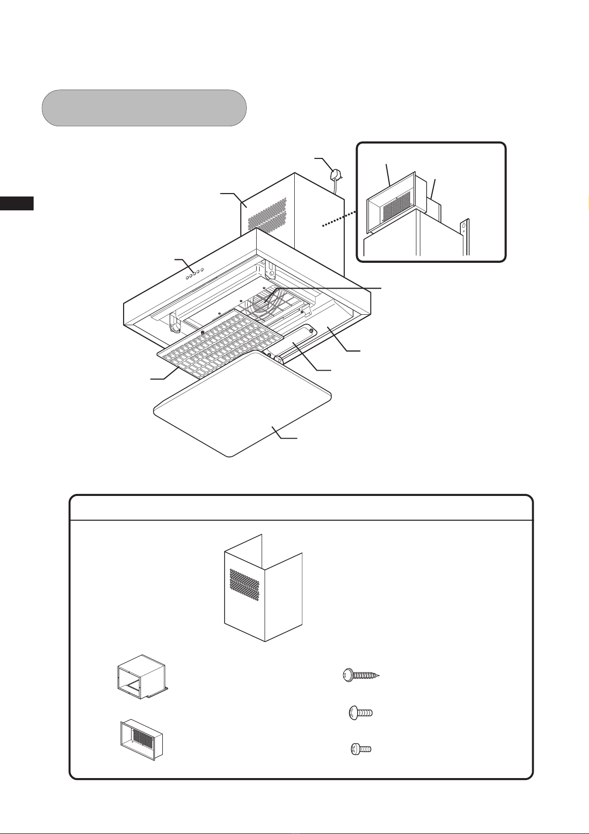
Mounting work should be done by 2 persons minimum.
The weight of the cooker hood is about 26kg.
Assembly
cautioned
Mounting
cautioned
Using
prohibited
Read the following safety instructions before mounting, and install the cooker hood properly and securely.
These instructions are for correct installation of the product to prevent any risk of hazards or damages inflicting on
you or others. The instructions are classified into 2 categories as "WARNING" and "CAUTION" depending on their
emergency and severity. Pay attention and strictly observe the instructions as they are critical for safety.
WARNING Alerts possible risk of death or heavy injury, if not observed.
CAUTION Alerts possible risk of injury or physical damage, if not observed.
WARNING
means prohibition. It indicates actions, if any, that mustn't be done.
(Left symbol: Disassembly prohibited)
means forcible execution. It indicates actions, if any, that must be done.
(Left symbol: Disconnect the plug from the wall outlet)
Example
Electric wiring must be made properly by the professional instaler or personnel.
Incorrect wiring may be cause of electric leakage or fire.
When dust accumulated on the blades of the power
plug or on their roots, wipe off well.
Fire may result in.
Don’t pour water on the electric parts.
Fire or electric shock may result in.
When there may be a gas leak in your gas hob,
don’t switch on or off the cooker hood.
Gas explosion may result in.
Choose a mounting location where sufficient air flow
is maintained.
CO poisoning may result if not ventilated adequately
while using a natural vent type stove, etc.
Wipe off
dust
Pouring
water
prohibited
Operation
prohibited
Air supply
cautioned
Assembly
cautioned
wet hand
Regulations concerning the discharge of air have to be fulfilled.
The air must not be discharged into a flue that is used for exhausting fumes
from appliances burning gas or other fuels.
Improper
discharge
prohibited
Observe
regulations