manuals.online logo
Brands
  1. Home
  2. •
  3. Brands
  4. •
  5. Fujitsu
  6. •
  7. Air Conditioner
  8. •
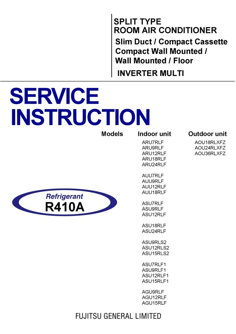
  9. Fujitsu ASU7RLF1 Reference manual

Fujitsu ASU7RLF1 Reference manual

Other manuals for ASU7RLF1

2

This manual suits for next models

20

Other Fujitsu Air Conditioner manuals

Fujitsu ASUG09LZBS User manual

Fujitsu

Fujitsu ASUG09LZBS User manual

Fujitsu ASYG09LTCB Service manual

Fujitsu

Fujitsu ASYG09LTCB Service manual

Fujitsu General ARXG45KHTB User manual

Fujitsu

Fujitsu General ARXG45KHTB User manual

Fujitsu AIRSTAGE UTB P Series User manual

Fujitsu

Fujitsu AIRSTAGE UTB P Series User manual

Fujitsu ABY14FBBJ User manual

Fujitsu

Fujitsu ABY14FBBJ User manual

Fujitsu D'EMPLOI User manual

Fujitsu

Fujitsu D'EMPLOI User manual

Fujitsu ASUG12LZAS User manual

Fujitsu

Fujitsu ASUG12LZAS User manual

Fujitsu UTY-XCSX User manual

Fujitsu

Fujitsu UTY-XCSX User manual

Fujitsu ABU18RULX Original operating manual

Fujitsu

Fujitsu ABU18RULX Original operating manual

Fujitsu AU G18LVLB Series Original operating manual

Fujitsu

Fujitsu AU G18LVLB Series Original operating manual

Fujitsu ASY14FSBCW User manual

Fujitsu

Fujitsu ASY14FSBCW User manual

Fujitsu ARTH18KMTAP User manual

Fujitsu

Fujitsu ARTH18KMTAP User manual

Fujitsu AS 18TF Series User manual

Fujitsu

Fujitsu AS 18TF Series User manual

Fujitsu ARUX12TLAV2 User manual

Fujitsu

Fujitsu ARUX12TLAV2 User manual

Fujitsu AIRSTAGE AUXS018GLEH User manual

Fujitsu

Fujitsu AIRSTAGE AUXS018GLEH User manual

Fujitsu GENERAL ASHG07KGTA Service manual

Fujitsu

Fujitsu GENERAL ASHG07KGTA Service manual

Fujitsu AUY35UIA-LV User manual

Fujitsu

Fujitsu AUY35UIA-LV User manual

Fujitsu RIDH07AVFJ User manual

Fujitsu

Fujitsu RIDH07AVFJ User manual

Fujitsu AS*12LEC Service manual

Fujitsu

Fujitsu AS*12LEC Service manual

Fujitsu AIRSTAGE ASHA18GATH User manual

Fujitsu

Fujitsu AIRSTAGE ASHA18GATH User manual

Fujitsu ASTA30LFC User manual

Fujitsu

Fujitsu ASTA30LFC User manual

Fujitsu ARY9LUAB User manual

Fujitsu

Fujitsu ARY9LUAB User manual

Fujitsu ASF30K-KM User manual

Fujitsu

Fujitsu ASF30K-KM User manual

Fujitsu Inverter Halcyon ASU24CL1 Service manual

Fujitsu

Fujitsu Inverter Halcyon ASU24CL1 Service manual

Popular Air Conditioner manuals by other brands

York HVHC 07-12DS Installation & owner's manual

York

York HVHC 07-12DS Installation & owner's manual

Carrier Fan Coil 42B Installation, operation and maintenance manual

Carrier

Carrier Fan Coil 42B Installation, operation and maintenance manual

intensity IDUFCI60KC-3 installation manual

intensity

intensity IDUFCI60KC-3 installation manual

Frigidaire FAC064K7A2 Factory parts catalog

Frigidaire

Frigidaire FAC064K7A2 Factory parts catalog

Sanyo KS2432 instruction manual

Sanyo

Sanyo KS2432 instruction manual

LG MultiV Series installation manual

LG

LG MultiV Series installation manual

CLIMAVENETA a-CHD U-2T 606+2209 OPERATING AND INSTALLATION Manual

CLIMAVENETA

CLIMAVENETA a-CHD U-2T 606+2209 OPERATING AND INSTALLATION Manual

Midea EWK06CW5 user manual

Midea

Midea EWK06CW5 user manual

Pioneer FAB Series installation manual

Pioneer

Pioneer FAB Series installation manual

SPT WA-1511S user manual

SPT

SPT WA-1511S user manual

Mitsubishi Electric Mr.Slim MSZ-A24NA operating instructions

Mitsubishi Electric

Mitsubishi Electric Mr.Slim MSZ-A24NA operating instructions

Mitsubishi Electric PUHZ-RP50VHA4 Service manual

Mitsubishi Electric

Mitsubishi Electric PUHZ-RP50VHA4 Service manual

Panasonic CS-S18HKQ Service manual

Panasonic

Panasonic CS-S18HKQ Service manual

Panasonic CS-E15NKE3 operating instructions

Panasonic

Panasonic CS-E15NKE3 operating instructions

Gree GWH18TC-K3DNA1B/I Service manual

Gree

Gree GWH18TC-K3DNA1B/I Service manual

Friedrich ZoneAire Compact P08SA owner's manual

Friedrich

Friedrich ZoneAire Compact P08SA owner's manual

Daikin R32 Split Series installation manual

Daikin

Daikin R32 Split Series installation manual

Daikin FFQ09Q2VJU Operation manual

Daikin

Daikin FFQ09Q2VJU Operation manual

manuals.online logo
manuals.online logoBrands
  • About & Mission
  • Contact us
  • Privacy Policy
  • Terms and Conditions

Copyright 2025 Manuals.Online. All Rights Reserved.

FUJITSU GENERAL AMERICA, INC
353 Route West. Fairfield, NJ 07004
Ph: 973-575-0381 Fx: 973-836-0449
Em: ServiceHVAC@fujitsugeneral.com
SERVICE BULLETIN
Number: 0030
Date: 9/25/14
TYPE: Field
PROBLEM Low Load Cooling / Heating Function Setting
SOLUTION Updated Firmware – Replacement Indoor Control Boards
MODEL: ASU7RLF1, ASU9RLF1, ASU12RLF1,
ASU9RL2, ASU12RL2, ASU9RLS2, ASU12RLS2,
ASU18RLF, ASU24RLF, AUU7RLF, AUU9RLF,
AUU12RLF, AUU18RLF, ARU7RLF, ARU9RLF,
ARU12RLF, ARU18RLF, ARU24RLF, AGU9RLF,
AGU12RLF, AGU15RLF
Production Serial Numbers:
Reference Table Below
Objective:
As a result of several case studies it has become apparent that homes with high levels of insulation require a different capacity control
algorithm in order to improve occupant comfort, and improve energy efficiency. This firmware update provides the contractor with the
ability to select between standard insulation and high insulation level home settings. The above mentioned models can be retrofitted
with a replacement board. Should you want the new firmware, reference the serial number list on the attached table, look for your model
and serial number to see if your unit already has the firmware update. If your unit is not on the list then the firmware is already installed
from factory and you can simply set the following function setting as needed. If your unit is on this list you will need to place an order for
a replacement board, which will be covered under our standard 5 year parts warranty, and conduct the following settings.
Room Temperature Sensor Control:
•Depending on the installed environment, correction of the room temperature sensor may be required.
•Select the appropriate control setting according to the installed environment.
•The temperature correction values show the difference from the standard setting “00” (manufacturer's recommended value).
Function Number Setting Value Setting Description
95 00 Standard insulation
◆
01 High insulation
Page 1 of 2
Model Serial Range Part Number Board Identification
ASU7RLF1 MWA00000 - MWA19379 K9709427354 K12JY-1402HSE-C1
ASU9RLF1 MXA00000 - MXA026182 K9709427330 K12JY-1402HSE-C1
ASU12RLF1 MYA000000 - MYA026820 K9709427347 K12JY-1401HSE-C1
ASU9RL2 EYA000000 - EYA007211 K9709170298 K11CN-1403HSE-C1
ASU12RL2 EYA000000 - EYA012671 K9709170304 K11CN-1404HSE-C1
ASU9RLS2 JQA000000 - JQA020146 K9708713410 K10CH-1401HSE-C1
ASU12RLS2 JRA000000 - JRA033554 K9708713427 K10CH-1402HSE-C1
ASU15RLS2 JSA000000 - JSA034491 K9708713434 K10CH-1403HSE-C1
ASU18RLF KSA000000 - KSA051177 K9708540368 K09DR-1403HSE-C1
ASU24RLF KTA000000 - KTA033603 K9708540375 K09DR-1404HSE-C1
AUU7RLF MVA000000 - MVA001421 K9709928011 K06AK-1400HSE-C1
AUU9RLF KUA000000 - KUA009021 K9709928028 K06AK-1401HSE-C1
AUU12RLF KVA000000 - KVA007667 K9709928035 K06AK-1402HSE-C1
AUU18RLF KWA000000 - KWA005975 K9709928042 K06AK-1403HSE-C1
ARU7RLF MUA000000 - MUA001442 K9709928059 K06AK-1404HSE-C1
ARU9RLF KYA000000 - KYA005911 K9709928066 K06AK-1405HSE-C1
ARU12RLF LNA000000 - LNA 007370 K9709928073 K06AK-1406HSE-C1
ARU18RLF LPA000000 - LPA007561 K9709928080 K06AK-1407HSE-C1
ARU24RLF LQA000000 - LQA003592 K9709928097 K06AK-1408HSE-C1
(
◆
… Factory Setting)
FUJITSU GENERAL AMERICA, INC
353 Route West. Fairfield, NJ 07004
Ph: 973-575-0381 Fx: 973-836-0449
Em: ServiceHVAC@fujitsugeneral.com
SERVICE BULLETIN
Number: 0030
Date: 9/25/14
TYPE: Field
Function Number Setting Value Setting Description
When select 95-00 When select 95-01
30
(For
Cooling
)
31
(For
Heating
)
00 *Standard Setting
◆
No Correction 0.0°F(0.0°C)
◆
01 No Correction 0.0°F(0.0°C) No Correction 0.0°F(0.0°C)
02 -1°F (-0.5°C)
More Cooling
Less Heating
03 -2°F (-1.0°C)
04 -3°F (-1.5°C)
05 -4°F (-2.0°C)
06 -5°F (-2.5°C)
07 -6°F (-3.0°C)
08 -7°F (-3.5°C)
09
-
8
°
F (
-
4.0
°
C)
Temperature Correction:
•Heat insulation condition (building insulation)
•Standard setting “00” allows system to rapidly respond to the cooling or heating load change when using room temperature sensor only.
•Heat insulation conditions differ according to the installed environment.
•Select “01” (High insulation) if the heat insulation structure of the building is high and does not require system to rapidly respond to cooling or heating load
changes.
•When “01” is selected, it prevents overheating (overcooling) at the start-up.
•When “01” is selected, all room temperature sensor and wire remote temp sensor settings will reset to factory setting.
•When “01” is selected, reset system (power off for two minutes then back on) and perform function settings 30, 31, 92, 93 to your desired temp control
level and reset power again.
•When “01” is selected, “standard setting “00” and no correction setting “01” are the same 0.0°F (0.0°C) Only when 95-01 is selected are these setting
values the same.
•The only function setting that will reset to factory settings when function 95-01 is selected are the temp correction settings 30,31, 92, 93.
•Confirm all function settings but do not re-enter function 95-00 or 95-01 as it will reset your temp correction settings.
•If you re-enter any of these two you must re-do all temp correction settings. (
◆
… Factory Setting)
Room Temperature Control for Wired Remote Controller Sensor
•Depending on the installed environment, correction of the wired remote temperature sensor may be required.
•Select the appropriate control setting according to the installed environment.
•Function 42-01 (unlocks thermo sensor) and function 48-01 (switches sensing from indoor unit to wired remote) need to be set for wired remote controller
sensor setting. You must ensure that the thermo sensor icon is displayed on the remote screen.
Function Number Setting Value Setting Description
92
(For Cooling)
93
(For Heating)
00 No correction 0.0°F(0.0°C)
◆
01 No correction 0.0°F(0.0°C)
02 -1°F (-0.5°C)
More Cooling / Less Heating
03 -2°F (-1.0°C)
04 -3°F (-1.5°C)
05 -4°F (-2.0°C)
06 -5°F (-2.5°C)
07 -6°F (-3.0°C)
08 -7°F (-3.5°C)
09 -8°F (-4.0°C)
10 +1°F (+0.5°C)
Less Cooling / More Heating
11 +2°F (+1.0°C)
12 +3°F (+1.5°C)
13 +4°F (+2.0°C)
14 +5°F (+2.5°C)
15 +6°F (+3.0°C)
16 +7°F (+3.5°C)
17 +8°F (+4.0°C)
Page 2 of 2
(For
Cooling
)
(For
Heating
)
09
-
8
°
F (
-
4.0
°
C)
10 +1°F (+0.5°C)
Less Cooling
More Heating
11 +2°F (+1.0°C)
12 +3°F (+1.5°C)
13 +4°F (+2.0°C)
14 +5°F (+2.5°C)
15 +6°F (+3.0°C)
16 +7°F (+3.5°C)
17 +8°F (+4.0°C)
* The standard setting temperature control changes depending on outside ambient temperature because it considers the outside heat load in relation with
outside ambient temperature which may require more cooling or more heating. Compared with function 95-01 correction 0.0°F(0.0°C), the room temperature
may possibly be higher in heating operation and lower in cooling operation if room heat load is lower than the capacity that can provide from system.
In case of slim duct type and floor/ceiling type models:
In floor console installations, select “01”
(
◆
… Factory Setting)
How to Enter Function Settings:
UTY-LNHUM / UTY-LRHUM AR-REC1U /AR-RED1U / AR-REG1U
Entering the Function Setting Mode:
Press the Fan (Control) button, Set Temp.(˄)and the Reset button
simultaneously then release the Reset button to enter the function
setting mode.
Selecting the Function Number and Setting Value
1. Press the Mode button first then press the Set Temp. (˄)(˅)
buttons to select the function number. (Press the Mode
button to switch between the left and right digits.)
2. Press the Fan button to proceed to setting the value. (Press
the Fan button again to return to the function number
selection.)
3. Press the Set Temp.(˄)(˅)buttons to select the setting.
(Press the Mode button to switch between the left and right
digits.)
4. Press the Timer Mode button and Start/Stop button, in the
order listed to confirm the settings.
5. Press the Reset button to cancel the function setting mode.
6. After completing the Function Setting, be sure to turn off
power to the outdoor disconnect for a minimum of one
minute and turn it on again.
Entering the Function Setting Mode:
Press the Powerful button, Set Temp.(˄)and Reset button
simultaneously then release the Reset button to enter the
function setting mode.
Selecting the Function Number and Setting Value
1. Press the Set Temp.(˄)(˅)buttons to select the function
number. (Press the Min. Heat button to switch between the
left and right digits.)
2. Press the Powerful button to proceed to setting the value.
(Press the Powerful button again to return to the function
number selection.)
3. Press the Set Temp.(˄)(˅)buttons to select the setting.
(Press the Min. Heat button to switch between the left and
right digits.)
4. Press the Mode button and then the Start/Stop button, in
the order listed to confirm the settings.
5. Press the Reset button to cancel the function setting mode.
6. After completing the Function Setting, be sure to turn off
power to the outdoor disconnect for a minimum of one
minute and turn it on again.
Disclaimer:
In order to perform some of these tests an electrical and/or refrigerant license is required. We strongly advise to check the Service manual for more detailed explanation. If you are not sure about these
recommendations please contact us at 866-952-8324.
UTY-RVNUM
Entering the Function Setting Mode:
1. Make sure the indoor unit is powered down and not running
otherwise you will be restricted from entering the Function
Settings menu.
2. From the monitor screen, press the Menu button twice.
3. Once at the submenu, press and hold the Screen Left and Screen
Right buttons for 5 seconds.
4. Select the Function Setting option from the list. From there you
will be in the Function Settings Menu and free to select function
number and setting values.
5. After completing the Function Setting, be sure to turn off power
to the outdoor disconnect for a minimum of one minute and turn
it on again.
Entering the Function Setting Mode:
1. Press the Set Temp.(˄)(˅)buttons and Fan button
simultaneously for more than 5 seconds to enter the
function setting mode.
2. Press the Set Back button to select the indoor unit number.
3. Press the Set Time buttons to select the function number.
4. Press the Set Temp. buttons (˄)(˅)to select the setting
value. The display flashes as shown to the right during
setting value selection.
5. Press the Timer Set button to confirm the setting. Press
the Set button for a few seconds until the setting value
stops flashing. If the setting value display changes or if “-
-” is displayed when the flashing stops, the setting value
has not been set correctly. (An invalid setting value may
have been selected for the indoor unit.)
6. Repeat steps 2 to 5 to perform additional settings. Press
the Set Temp. buttons (˄)(˅)and Fan button
simultaneously again for more than 5 seconds to cancel
the function setting mode. In addition, the function setting
mode will be automatically canceled after 1 minute if no
operation is performed.
7. After completing the Function Setting, be sure to turn off
power to the outdoor disconnect for a minimum of one
minute and turn it on again.
UTY-RNBYU /UTY-RNNUM
Entering the Function Setting Mode:
1. Press both the Temp. Up and Down buttons (˄)(˅)and FAN
together for more than 5 seconds simultaneously. Then, shift to
Function Setting Mode.
2. Press the Temp. Up or Temp. Down button (˄)(˅)and select
the indoor unit number. Then, press the Fan button.
Function Number & Setting Number Setting
3. “Function Number” display blinks. Then, display Number by
pressing the Temp. Up or Temp. Down button.
4. When the “Setting Number” blinks, press the Fan button to set
the Setting number by pressing the Temp. Up or Temp. Down
button (˄)(˅).
5. Fix the setting by pressing the power button. (Data is transferred
to the indoor unit).
6. After completing the Function Setting, be sure to turn off power
to the outdoor disconnect for a minimum of one minute and turn
it on again.
UTY-RSNUM
Appendix (1)