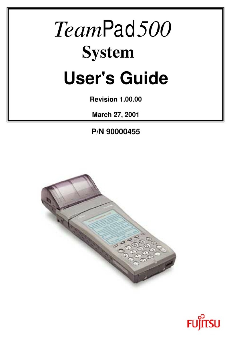
Fujitsu TeamPad 500 User manual

For Maintenance Purpose Only
TeamPad 500
Operations Guide
Rev 1.0
90000454

To Safely Use This Product
About this Manual:
This manual contains important information for safely using this product. Thoroughly read this manual
before using the product. In particular, thoroughly read until fully understanding the “Notes on Safety”
in this manual before using this product. Refer to this manual when necessary, so keep this manual in an
easy-to-refer to place.
FUJITSU makes every effort to prevent users and observers from being injured and to prevent property
from suffering from damage. To ensure no harm to you, observers, or the equipment itself, be sure to
use the product according to the instructions in this manual.
First Edition March 2001
The contents of this manual may be revised without prior notice.
All Rights Reserved, Copyright © FUJITSU KIDEN LIMITED 2000

-i-
FCC WARNING:
Changes of modifications not expressly approved by the party responsible for compliance could void the
user's authority to operate the equipment.
This equipment has been tested and found to comply with the limits for a Class B digital device, pursuant
to Part 15 of the FCC Rules. These limits are designed to provide reasonable protection against harmful
interference in a residential installation. This equipment generates, uses, and can radiate radio
frequency energy and, if not installed and used in accordance with the instruction, may cause harmful
interference to radio communications. However, there is no guarantee that interference will not occur
in a particular installation. If this equipment does cause harmful interference to radio or television
reception, which can be determined by turning the equipment off and on, the user is encouraged to try to
correct the interference by one or more of the following measures:
-Reorient of relocate the receiving antenna.
-Increase the separation between the equipment and receiver.
-Connect the equipment into an outlet on a circuit different from that to which the receiver is
connected.
-Consult the dealer or an experienced radio/TV technician for help.

-ii-
REVISION RECORD
REVISION DATE ISSUED DESCRIPTION OF CHANGE PAGE (S)
1.0 March 2001 Original issue
Document Code No.: 90000454
Date: March, 2001

-iii -
Contents
Part I HHCs
Chapter 1 Outline ............................................................................................................................................1-1
1.1 HHC Types and Options.......................................................................................................................1-1
1.2 Exterior Views ......................................................................................................................................1-1
1.3 Specifications .......................................................................................................................................1-4
Chapter 2 Operations ......................................................................................................................................2-1
2.1 Holding the HHC..................................................................................................................................2-2
2.2 Turning the HHC On and Off...............................................................................................................2-2
2.3 Adjusting LCD Contrast.......................................................................................................................2-2
2.4 Turning On the LCD Backlight ............................................................................................................2-2
2.5 Key Functions.......................................................................................................................................2-3
2.5.1 Key labels.......................................................................................................................................2-3
2.5.2 Functions of major keys...............................................................................................................2-4
2.5.3 Cover of roll paper (with a printer).............................................................................................2-5
2.5.3.1 Handling the cover of roll paper.......................................................................................2-5
2.5.3.2 Replacing the roll paper....................................................................................................2-6
2.5.4 Replacing the printer...................................................................................................................2-11
2.6 Handling the Battery...........................................................................................................................2-11
2.6.1 Recharging the battery ................................................................................................................2-11
2.6.2 Replacing the battery pack..........................................................................................................2-12
2.7 Lithium Back-up Batteries (auxiliary batteries) ..............................................................................2-15
2.8 RS-232CInterface..............................................................................................................................2-17
2.9 Memory Cards (Option).....................................................................................................................2-17
2.10 Cleaning.............................................................................................................................................2-18
2.11 Notes.................................................................................................................................................2-20
2.11.1 Installation.................................................................................................................................2-20

1-1
Chapter 1 Outline
This chapter provides general information about the TeamPad 500 Series hand-held computers
(HHCs), including their exterior views and specifications.
1.1 HHC Types and Options
In addition to being completely compatible with the industry-standard Windows-CE machines, the
TeamPad 500 Series HHCs will support options such as memory cards (those controlling modems
and LANs) and bar code scanners.
The HHCs run Windows-CE as an operating system. In addition, specialized application software is
available to meet specific and general needs.
The TeamPad 500 Series HHCs are grouped into the following eight types:
•FHT532A1:24-key, monochrome LCD, without a printer, without a SS radio antenna
•FHT532R1:24-key, monochrome LCD, without a printer, with a SS radio antenna
•FHT542A1:24-key, monochrome LCD, with a printer, without a SS radio antenna
•FHT542R1:24-key, monochrome LCD, with a printer, with a SS radio antenna
The HHCs are connectable to the following units:
•FHTLA551W:Communication interface unit
Unit for connecting HHC to a modem or main system. The main battery in HHC can be charged.
(RS-232C I/F:SD/RD/RS/CS
•FHTLA552W:Communication interface unit
Unit for connecting HHC to a modem or main system. The main battery in HHC can be charged.
(RS-232C I/F:SD/RD/CS/ER/DR/CS
FHTCH551 :Holder
In-vehicle unit for converting data from the HHC optical element into the RS-232C interface
(SD, RD only)
1.2 Exterior Views
The HHCs are powered from an internal lithium-ion battery pack (which is recharged the same time
the HHC is placed in the CIU/holder). They come with 32 MB of RAM installed (not including an
optional memory card). This generous amount of RAM, plus the CPU, allows the HHCs to be used as
personal computers.
RAM data is protected by internal lithium back-up batteries. Each HHC can communicate with a host
computer or another HHC by way of its RS-232C interface or PC card interface or IrDA interface.
HHCs connected to a printer (line / thermal) can print out data directly.
Connecting an optional scanner to a HHC will enables it to scan and record bar-code images.
Figure 1.2.1 shows FHT522A1 HHC with a printer.
Figure 1.2.2shows FHT522A1 HHC without a printer.

1-2
Figure 1.2.1 TeamPad 500 Series HHC with a printer

1-3
Figure 1.2.2 TeamPad 500 Series HHC without a printer

1-4
1.3 Specifications
This section summarizes the specifications of the TeamPad 500 Series HHCs.
Table 1.1 TeamPad 500 Series HHC specifications (1/2)
ITEM without Printer with Printer
Control CPU 64bit RISC CPU
Memory RAM: 32MB
ROM: 32MB
OS Windows-CE V2.12
Display Size 240 ×320 pixels
Character and line Alphanumeric: 21ch ×15 line (Standard font: 9 ×16 dot)
(Test font)
Graphic font: 21ch ×15 line (Standard font: 9 ×16 dot)
Character Alphanumeric
LCD Light LED Light
Controller QVGA(SED1376-EPSON)
Keyboard Tactile 24 keys
Pen, Touch panel Pen and touch panel
IrDA 1.1 I/F Max.4MbpsInterface
RS-232C I/F Max. 115.2 kbps
(SD/RD/RS/CS/ER/DR/VDD/SG/CD)
PCMCIA TYPE 2 ×1 slot (only FHT5**A1)
Printer Method N/A Line thermal (512 dot, 0.125
mm pitch)
Speed 24 L/s (1p, 8×16 pixels
"H"-12 char/line)
Character/line ANK: 32 char (12 ×24)
Character ANK/JIS level-1/-2
Paper 70 mm thermal paper
1P-roll, 2P-single
Others Semi-auto-load,
Detect printing position

1-5
Table 1.1 TeamPad 500 Series HHC specifications (2/2)
ITEM Without Printer with Printer
Power Main battery Lithium-ion battery pack (7.2 V/1200 mAh)
Back-up battery Lithium rechargeable batteries (3.0 V/90 mAh)
Operatingtime
*Note2
(with a new battery)
(At 3000 lines printed)
Storage time
(with a new battery)
(1) 10 days (25ºC, with full-charged Main battery)
(2) 10hours (25ºC, without Main battery)
Charging time Approximately 2.5 hours
Operatingtemperature/humidity -5ºC to +50ºC
Up to85%RH
-5ºC to +50ºC
Upto85%RH
Storage temperature/humidity -20ºC to +60ºC
Upto95%RH
Size Measurement 85 ×210 ×28.5 mm
Weight Approximately 420g (.93 lb) Approximately 470g (1.04lb)
Environment Splashing at 3-5mm/min Splashing at 3-5 mm (with
Printer cover)
5 ft. drop to concrete 4 ft. drop to concrete
ESD 15 kV
Miscellaneous RF: Lucent modem (SS) [PCMCIA Card]
Option :CIU(RS-232C:SD/RD/RS/CS/ER/DR/CD/RI/SG)
:Holder
:Pack Charger (A lithium-ion battery charger)
:Charger (It is used for charging TP500 direct)
Approvals FCC Part 15 class B
*Note2) Assumption of battery consumption
: Main CPU operating rate (10% Run, 90% Idle)
: light off
+20°C15h
0°C8h
+20°C15h
0°C6h
or below

2-1
Chapter 2 Operations
This chapter provides operating instructions for the TeamPad 500 Series hand-held computers
(HHCs).
Figure 2.1 shows the keyboard and display (LCD) of a HHC. The HHC is powered from the internal
lithium-ion battery pack.
Figure 2.1 HHC keyboard and display
Power Switch
RS232C connector
Optical connector
Keyboard
CFcard
LCD
Roll Paper Cover
FHT541 only

2-2
2.1 Holding the HHC
The HHCs are furnished with a hand strap on their back so you can hold them securely during use.
Hold the HHC as shown in Figure 2.1.1.
Figure 2.1.1 Holding the HHC
2.2 Turning On and Off the HHC Power
To turn on the HHC, press the [PWR] key. (Press time approximately 2 seconds)
To turn it off, press the [PWR] key.
2.3 Adjusting LCD Contrast
F8([SFT] + [F3])key: Increases contrast.
F9([SFT] + [F4])key: Decreases contrast.
To adjust the LCD contrast, press theabove keys until the desired contrast is attained.
2.4 Turning On and Off the LCD Backlight
F7([SFT] + [F2]): turn on and off
To turn on the LCD light (yellow), press the [SFT] + [F2]key. Press againto turn o ff the LCD light.
The auto-light off feature can be accessed and modified through the programming. To turn on the
LCD light again, press the [SFT]+ [F2] key again.
Charging terminals
Charging jack
Battery cover
Hand strap
PCMCIA slot
Reset Switch
Knob

2-3

2-4
2.5 Key Functions
As stated in Chapter 1, the HHC keyboard contains a set of24 keys. This section shows their key
labels and explains the functions of major keys.
2.5.1 Key Labels
Figure 2.5.1 shows the labels of those keys that are functional when the [SFT] key is pressed and
those that are functional when it is not pressed.
(1) Normal state (2) When the [SFT] key is pressed
* F6 key is operable only on HHCs equipped with a printer.
Figure 2.5.1 Key labels
F1 F2 F3 F4 F5
PWR 7 8 9 CLR
4 5 6 BKS
1 2 3
ENT
SFT 0 00 .
F6(*) F7 F8 F9 F10
-
SYS
SFT

2-5
2.5.2 Functions of major keys
The table below describes typical functions of major keys.
[Examples]
Key Function
F1 (Function 1) (Note)
F2 (Function 2) (Note)
F3 (Function 3) (Note)
F4 (Function 4) (Note)
F5 (Function 5) (Note)
F6(Function 6) Feeds paper (only on HHCs equipped with a printer).
F7 (Function7) Turns on or off the LCD-light.
F8(Function8) Increases contrast.
F9 (Function9) Decreases contrast.
F10(Function10) Displays the Screen Key-Board
SYS (SYStem) Starts tools, such as one for adjusting the buzzer volume,and
adjusting the Touch Panel.
PWR (PoWeR on/off)Turnson/offthe HHC.
CLR (CLeaR)(Note)
BKS (BacK Space) Erases the last character of the text on display.
ENTer Validates an entry.
SFT(ShiFT) Switches between alphabetic and numeric characters.
-Displays the current line.
Displays the previous line.
Displays the next line.
Moves the cursor to left (by one position).
Moves the cursor to right (by one position).
0to9 Enter numeric characters
Note:
These keys may depend in part on applications for their functions.

2-6
2.5.3 Roll paper cover (with a printer)
This section describes how to handle the roll paper cover and how to replace the roll paper.
2.5.3.1 Handling the roll paper cover
This section describes how to attach the roll paper cover and how to remove the roll paper cover.
−Attaching the roll paper cover
(1) Open the roll paper cover.
(2) As shown in the Figure 2.5.3.1, align the grooveA on the top of the HHC with the groove B on
the roll paper cover. Then, slide the roll paper cover in the direction of the arrow until it is
firmly in place.
(3) Close the printer cover.
−Removing the roll paper cover
Perform the attaching procedure in reverse order.
Figure 2.5.3.1 Roll paper cover
B
A

2-7
2.5.3.2 Replacing the roll paper
This section describes how to replace the roll paper.
(1) Slide the side lock in the direction of the arrow.
(2) Open the roll paper cover. (Figure 2.5.3.2 (a))
(3) Insert the roll paper into the opening. (Figure 2.5.3.2 (b))
(a)
(b)
Figure 2.5.3.2 Replacing the roll paper

2-7
2.5.4 Replacing the printer
This section describes how to replace the printer unit.
Notes: After the printer operates, wait a while. Then, replace the printer unit.
The motor or printer head may overheat and may cause burn.
The following describes how to remove and attach the printer unit.
−Removing the printer unit
(1) Open the printer unit. (Figure 2.5.4 (a))
(2) Use the screwdriver to remove the screw of the printer unit holder. (Figure 2.5.4 (b))
(a)
(b)
Figure 2.5.4.1 Removing the printer unit (1/3)

2-8
(4) Lift the printer unit to remove it from the cabinet. (Figure 2.5.4.1 (c))
(5) Disengage the connector latches and remove the flexible cable from connector.
Notes:
Carefully remove the cable. Otherwise, connector may break.
(6) The printer unit is removed.
(c)
Figure 2.5.4.1 Removing the printer unit
Connector

2-9
−Attaching the printer unit
Perform the removing procedure in reverse order.
(1) Firmly insert the cables that correspond to connector. (Figure 2.5.4.2 (a))
(2) Set the connector latchwith your finger toward the direction of arrow.
(3) Mount the printer unit in the HHC unit. (Figure 2.5.4.2 (b))
(4) Tighten two screwsto fix the printer unit. (Figure 2.5.4.2 (c))
(5) Close the printer cover.
(a)
Figure 2.5.4.2 Attaching the printer unit (1/2)
(b)
Table of contents
Other Fujitsu Handheld manuals

Fujitsu
Fujitsu Pocket Loox T810 User manual

Fujitsu
Fujitsu IPAD100-20 User manual

Fujitsu
Fujitsu 200 User manual

Fujitsu
Fujitsu TeamPad500 System User manual

Fujitsu
Fujitsu LOOX600 User manual

Fujitsu
Fujitsu TeamPad PBT7500-16 User manual

Fujitsu
Fujitsu 200 User manual

Fujitsu
Fujitsu Pocket LOOX 600 Product information sheet

Fujitsu
Fujitsu FOMA F884i Docomo User manual

Fujitsu
Fujitsu iPAD100 series User manual