Fujitsu ETERNUS AB Series Owner's manual

A3CA08733-A101-01
FUJITSU Storage ETERNUS AB/HB Series
Maintaining FUJITSU Storage ETERNUS AB6100
Hardware

|Contents|
Contents
Batteries.......................................................................................................... 4
Overview and requirements................................................................................................................... 4
Requirements for replacing a battery......................................................................................... 4
Replace battery...................................................................................................................................... 4
Place controller offline................................................................................................................4
Remove controller canister..........................................................................................................5
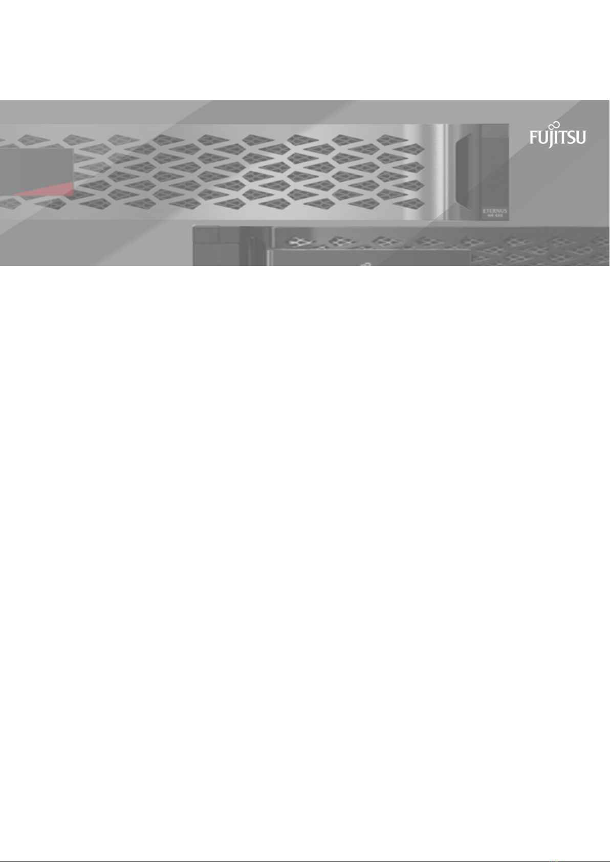
Remove failed battery.................................................................................................................6
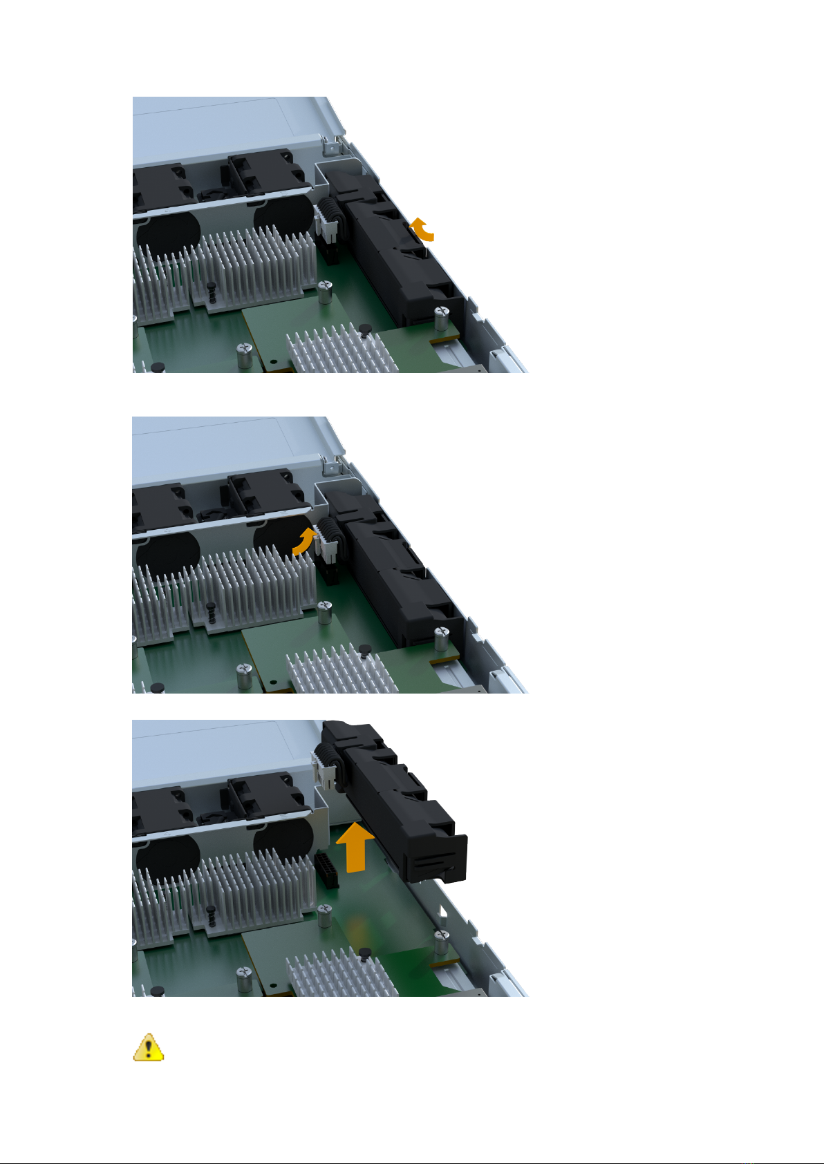
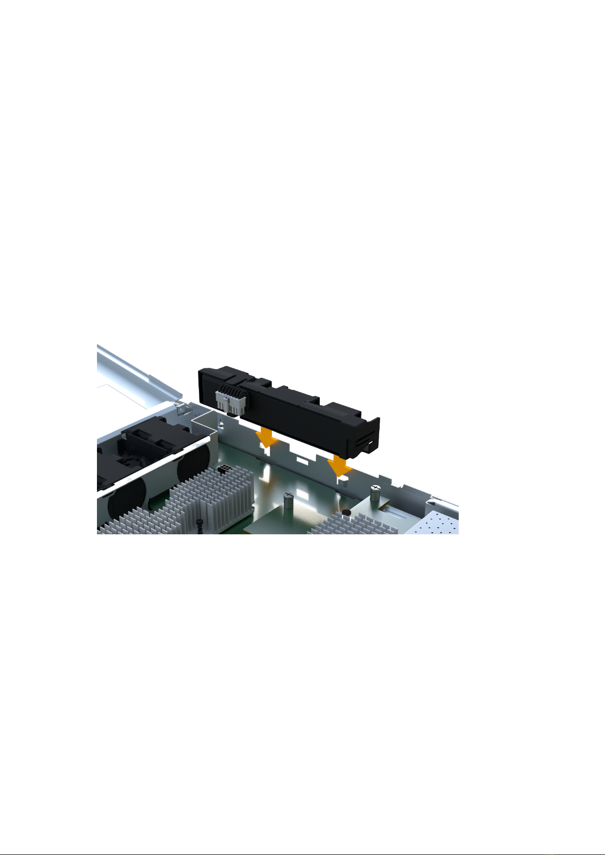
Install new battery......................................................................................................................8
Reinstall controller canister.........................................................................................................8
Complete battery replacement....................................................................................................9
Controllers..................................................................................................... 11
Overview and requirements................................................................................................................. 11
Requirements for replacing a controller....................................................................................11
Replace controller.................................................................................................................................11
Prepare to replace controller.....................................................................................................11
Remove failed controller...........................................................................................................12
Install new controller................................................................................................................ 19
Complete controller replacement..............................................................................................24
DIMMs............................................................................................................26
Overview and requirements................................................................................................................. 26
Requirements for replacing DIMMs...........................................................................................26
Replace DIMMs.....................................................................................................................................26
Determining if you need to replace DIMMs in a controller........................................................26
Place controller offline..............................................................................................................27
Remove controller canister........................................................................................................27
Remove DIMMs......................................................................................................................... 28
Install new DIMMs.................................................................................................................... 29
Reinstall controller canister.......................................................................................................30
Complete DIMMs replacement.................................................................................................. 31
Drives............................................................................................................. 32
Overview and requirements................................................................................................................. 32
Requirements for replacing drives............................................................................................ 32
Replace drive........................................................................................................................................33
Prepare to replace drive............................................................................................................33
Remove drive............................................................................................................................ 33
Install new drive....................................................................................................................... 34
Complete drive replacement..................................................................................................... 34
Fans................................................................................................................36
Overview and requirements................................................................................................................. 36
Requirements for replacing a fan............................................................................................. 36
Replace a fan....................................................................................................................................... 36
Place controller offline..............................................................................................................36
Remove controller canister........................................................................................................37
Remove failed fan.....................................................................................................................38
Install new fan..........................................................................................................................38
Reinstall controller canister.......................................................................................................39
Complete fan replacement........................................................................................................40
Host interface cards...................................................................................... 42
Overview and Requirements.................................................................................................................42
Add host interface cards.......................................................................................................................42
Place controller offline..............................................................................................................42
Remove controller canister........................................................................................................43
ii

|Contents|
Add the new host interface card...............................................................................................44
Reinstall the controller canister................................................................................................ 45
Complete adding host interface card........................................................................................ 46
Upgrade host interface card................................................................................................................. 47
Place controller offline..............................................................................................................47
Remove controller canister........................................................................................................48
Remove the host interface card................................................................................................ 49
Upgrade host interface card......................................................................................................51
Reinstall controller canister.......................................................................................................52
Complete the host interface card upgrade................................................................................53
Replace failed host interface card........................................................................................................ 54
Place the controller shelf offline...............................................................................................54
Remove controller canister........................................................................................................55
Remove the host interface card................................................................................................ 56
Replace host interface card.......................................................................................................58
Reinstall controller canister.......................................................................................................59
Complete host interface card replacement................................................................................60
Host port protocol conversion...................................................................... 61
Overview and requirements................................................................................................................. 61
Requirements for changing the host protocol...........................................................................61
Change host protocol........................................................................................................................... 61
Determine whether you have dual-protocol SFPs......................................................................61
Obtain the feature pack key..................................................................................................... 62
Stop host I/O............................................................................................................................. 64
Change the feature pack...........................................................................................................65
Complete host protocol conversion.......................................................................................................65
Complete NVMe over InfiniBand, NVMe over RoCE conversion, or NVMe over FC.......................65
Power Supplies..............................................................................................67
Overview and requirements................................................................................................................. 67
Requirements for replacing a power supply..............................................................................67
Replace a power supply....................................................................................................................... 67
Place controller offline..............................................................................................................67
Power down the controller........................................................................................................68
Remove failed power supply.....................................................................................................68
Install new power supply.......................................................................................................... 69
Complete power supply replacement........................................................................................ 70
Copyright............................................................................................................................72
Trademark.......................................................................................................................... 73
How to send comments about documentation and receive update notifications...........74
iii

|Batteries |
Batteries
A battery is included with a controller and preserves cached data if the AC power fails.
Overview and requirements
Before you replace a battery, you need to be aware of certain requirements and considerations.
Requirements for replacing a battery
If you plan to replace a failed battery, keep the following requirements in mind.
Recovery Guru alerts
If the Recovery Guru in SANtricity System Manager reports one of following statuses, you must replace the
affected battery:
• Battery Failed
• Battery Replacement Required
From SANtricity System Manager, review the details in the Recovery Guru to confirm that there is an issue with
a battery and to ensure no other items must be addressed first.
Requirements for replacing a battery
If you plan to replace a battery, keep the following requirements in mind.
• You must have installed SANtricity System Manager on a management station, so you can use the storage
array's command line interface (CLI).
If this software has not yet been installed, follow the instructions in the Linux express configuration,
Windows express configuration, or VMware express configuration to download and install it.
• You must have a replacement battery.
• You have an ESD wristband, or you have taken other antistatic precautions.
• You must use labels to identify each cable that is connected to the controller canister.
This section describes how to replace a battery in the following controller shelves:
• AB6100 controller shelf
Replace battery
Each controller canister includes a battery that preserves cached data if the AC power fails. If the Recovery
Guru in SANtricity System Manager reports either a Battery Failed status or a Battery Replacement Required
status, you must replace the affected battery.
Place controller offline
You must place the affected controller offline so you can safely remove the failed battery. You must back up
the configuration and collect support data first. Then, you can take the affected controller offline.
Before you begin
• Make sure that no volumes are in use or that you have a multipath driver installed on all hosts using these
volumes.
Procedure
1. From SANtricity System Manager, review the details in the Recovery Guru to confirm that there is an issue
with a battery and to ensure no other items must be addressed first.
4

|Batteries |
2. From the Details area of the Recovery Guru, determine which battery to replace.
3. Back up the storage array's configuration database.
If a problem occurs when you remove a controller, you can use the saved file to restore your configuration.
a) In System Manager, navigate to the support page.
b) Select the Support Center tab.
c) Select the Diagnostics tab.
d) Select Collect Support Data.
4. If the controller is not already offline, take it offline now using SANtricity System Manager.
•a. Select Hardware.
b. If the graphic shows the drives, select Show back of shelf to show the controllers.
c. Select the controller that you want to place offline.
d. From the context menu, select Place offline, and confirm that you want to perform the operation.
Note: If you are accessing SANtricity System Manager using the controller you are attempting to take
offline, a SANtricity System Manager Unavailable message is displayed. Select Connect to an alternate
network connection to automatically access SANtricity System Manager using the other controller.
5. Wait for SANtricity System Manager to update the controller's status to offline.
Attention: Do not begin any other operations until after the status has been updated.
What to do next
Go to Remove controller canister.
Remove controller canister
You remove the controller canister so you can replace the failed battery with a new one. Disconnect all the
cables then you can slide the controller out of the controller shelf.
Before you begin
• You must use labels to identify each cable that is connected to the controller canister.
• You have an ESD wristband, or you have taken other antistatic precautions.
• You have prepared a flat, static free work area.
Procedure
1. Put on an ESD wristband or take other antistatic precautions.
2. Label each cable that is attached to the controller canister.
3. Disconnect all the cables from the controller canister.
Attention: To prevent degraded performance, do not twist, fold, pinch, or step on the cables.
4. Confirm that the Cache Active LED on the back of the controller is off.
5. Squeeze the handles on either side of the controller, and pull back until it releases from the shelf.
5

|Batteries |
6. Using two hands and the handles, slide the controller canister out of the shelf. When the front of the
controller is free of the enclosure, use two hands to pull it out completely.
Attention: Always use two hands to support the weight of a controller canister.
7. Place the controller canister on a flat, static-free surface.
What to do next
Go to Remove failed battery.
Remove failed battery
You must remove the failed battery so you can install the new one. Remove the battery by squeezing the tab
and disconnecting the connector housing. Then, you can pull the battery out of the controller.
Procedure
1. Remove the controller canister's cover by unscrewing the single thumbscrew and lifting the lid open.
2. Locate the black 'press' tab on the side of the controller.
6

|Batteries |
3. Unlatch the battery by pressing the tab and squeezing the battery casing.
4. Gently squeeze the connector housing the battery wiring. Pull up, disconnecting the battery from the
board.
5. Lift the battery out of the controller and place on a flat, static-free surface.
6. Follow the appropriate procedures for your location to recycle or dispose of the failed battery.
Warning: To comply with International Air Transport Association (IATA) regulations, never ship a
lithium battery by air unless it is installed within the controller shelf.
7

|Batteries |
What to do next
Go to Install new battery.
Install new battery
You must install a new battery when the old one has failed. Align the new battery with the side of the
controller and then plug the connector into the board.
Before you begin
• You have removed the failed battery from the controller canister.
• You have the replacement battery.
• You have an ESD wristband, or you have taken other antistatic precautions.
Procedure
1. Unpack the new battery, and set it on a flat, static-free surface.
Important: To comply with IATA safely regulations, replacement batteries are shipped with a state of
charge (SoC) of 30 percent or less. When you reapply power, keep in mind that write caching does not
resume until the replacement battery is fully charged and it has completed its initial learn cycle.
2. Insert the battery into the controller by lining up the battery casing with the metal latches on the side of
the controller.
The battery clicks into place.
3. Plug the battery connector back into the board.
What to do next
Go to Reinstall controller canister
Reinstall controller canister
After you install the new battery, you reinstall the controller into the controller shelf. Close the cover and use
the handles to slide the controller into the controller shelf.
Procedure
1. Lower the cover on the controller canister and secure the thumbscrew.
2. While squeezing the controller handles, gently slide the controller canister all the way into the controller
shelf.
Note: The controller audibly clicks when correctly installed into the shelf.
8

|Batteries |
What to do next
Go to Complete battery replacement.
Complete battery replacement
You complete a battery replacement by placing the controller online to confirm the new battery is working
correctly. Then, you can collect support data and resume operations.
Procedure
1. Place controller online.
a) In System Manager, navigate to the hardware page.
b) Select Show back of controller.
c) Select the controller with the replaced battery.
d) Select Place online from the drop down list.
2. As the controller boots, check the controller LEDs.
When communication with the other controller is reestablished:
• The amber Attention LED remains on.
• The Host Link LEDs might be on, blinking, or off, depending on the host interface.
3. When the controller is back online, confirm that its status is Optimal and check the controller shelf’s
Attention LEDs.
If the status is not Optimal or if any of the Attention LEDs are on, confirm that all cables are correctly
seated and the controller canister is installed correctly. If necessary, remove and reinstall the controller
canister.
Note: If you cannot resolve the problem, contact technical support.
4. Click Support > Upgrade Center to ensure that the latest version of SANtricity OS is installed.
As needed, install the latest version.
5. Verify that all volumes have been returned to the preferred owner.
a) Select Storage > Volumes. If current owner and preferred owner are not listed select All volumes >
Columns. Select current owner and preferred owner then recheck to verify that volumes are distributed
to their perferred owners.
b) If volumes are all owned by preferred owner continue to Step 6.
c) If none of the volumes are returned, you must manually return the volumes. Go to Storage > Volumes >
More > Redistribute volumes.
d) If only some of the volumes are returned to their preferred owners after auto-distribution or manual
distribution you must check the recovery guru for host connectivity issues.
e) If there is no recovery guru present or if following the recovery guru steps the volumes are still not
returned to their preferred owners contact support.
9

|Batteries |
6. Collect support data for your storage array using SANtricity System Manager.
a. Select Support > Support Center > Diagnostics.
b. Select Collect Support Data.
c. Click Collect.
The file is saved in the Downloads folder for your browser with the name support-data.7z.
Results
Your battery replacement is complete. You can resume normal operations.
10

Controllers
A controller consists of a board, firmware, and software. It controls the drives and implements the System
Manager functions. This section describes how to replace a single controller or both controllers in your AB6100
controller shelf.
Overview and requirements
Before you replace a controller, you need to be aware of certain requirements and considerations.
Requirements for replacing a controller
If you plan to replace a controller, keep the following requirements in mind.
Requirements for replacing a failed controller
• You must have a replacement controller canister with the same part number as the controller canister you
are replacing.
• You have an ESD wristband, or you have taken other antistatic precautions.
• You must use labels to identify each cable that is connected to the controller canister.
• You must have a #1 Phillips screwdriver.
• You must have installed SANtricity System Manager on a management station, so you can use the storage
array's command line interface (CLI).
If this software has not yet been installed, follow the instructions in the Linux express configuration,
Windows express configuration, or VMware express configuration to download and install it.
You can replace a controller canister while your storage array is powered on and performing host I/O
operations, as long as the following conditions are true:
• The second controller canister in the shelf has Optimal status.
• The OK to remove field in the Details area of the Recovery Guru in SANtricity System Manager displays Yes,
indicating that it is safe to remove this component.
This section describes how to replace a controller canister in the following controller shelves:
• AB6100 controller shelf
Replace controller
This section describes the steps to replace a single controller in your AB6100 controller shelf.
Before you begin
When you replace a failed controller canister, you must remove the battery, power supply, DIMMs, fans, and
HIC, if one is installed, from the original controller canister, and install them in the replacement controller
canister.
You can determine if you have a failed controller canister in two ways:
• The Recovery Guru in SANtricity System Manager directs you to replace the controller canister.
• The amber Attention LED on the controller canister is on, indicating that the controller has a fault.
Prepare to replace controller
When a controller canister fails, you must replace it. You prepare to replace a controller canister by verifying
that the replacement controller canister has the correct FRU part number, backing up the configuration, and
collecting support data.
11

|Controllers|
Procedure
1. Unpack the new controller canister, and set it on a flat, static-free surface.
Save the packing materials to use when shipping the failed controller canister.
2. Locate the MAC address and FRU part number labels on the back of the controller canister.
3. From SANtricity System Manager, locate the replacement part number for the controller canister you are
replacing.
When a controller has a fault and needs to be replaced, the replacement part number is displayed in the
Details area of the Recovery Guru. If you need to find this number manually, follow these steps:
a) Select Hardware.
b) Locate the controller shelf, which is marked with the controller icon .
c) Click the controller icon.
d) Select the controller, and click Next.
e) On the Base tab, make a note of the Replacement Part Number for the controller.
4. Confirm that the replacement part number for the failed controller is the same as the FRU part number for
the replacement controller.
Attention: Possible loss of data access – If the two part numbers are not the same, do not
attempt this procedure. In addition, if the failed controller canister includes a host interface card
(HIC), you must install that HIC into the new controller canister. The presence of mismatched
controllers or HICs causes the new controller to lock down when you bring it online.
5. Back up the storage array's configuration database.
If a problem occurs when you remove a controller, you can use the saved file to restore your configuration.
a) In System Manager, navigate to the support page.
b) Select the Support Center tab.
c) Select Diagnostics tab.
d) Select the Collect Support Data.
6. If the controller is not already offline, take it offline now using SANtricity System Manager.
•a. Select Hardware.
b. If the graphic shows the drives, select Show back of shelf to show the controllers.
c. Select the controller that you want to place offline.
d. From the context menu, select Place offline, and confirm that you want to perform the operation.
Note: If you are accessing SANtricity System Manager using the controller you are attempting to take
offline, a SANtricity System Manager Unavailable message is displayed. Select Connect to an alternate
network connection to automatically access SANtricity System Manager using the other controller.
7. Wait for SANtricity System Manager to update the controller's status to offline.
Attention: Do not begin any other operations until after the status has been updated.
8. Select Recheck from the Recovery Guru, and confirm that the OK to remove field in the Details area
displays Yes, indicating that it is safe to remove this component.
What to do next
Go to Remove failed controller.
Remove failed controller
You remove a controller canister to replace the failed canister with a new one. You remove the failed controller
canister by removing the controller from the controller shelf and removing the battery, host interface card,
power supply, DIMMs, and fans.
Remove controller canister
You remove the failed controller canister so you can replace it with a new one. Disconnect all the cables then
you can slide the controller out of the controller shelf.
12

|Controllers|
Before you begin
• You must use labels to identify each cable that is connected to the controller canister.
• You have an ESD wristband, or you have taken other antistatic precautions.
• You have prepared a flat, static free work area.
Procedure
1. Put on an ESD wristband or take other antistatic precautions.
2. Label each cable that is attached to the controller canister.
3. Disconnect all the cables from the controller canister.
Attention: To prevent degraded performance, do not twist, fold, pinch, or step on the cables.
4. If the controller canister has a HIC that uses SFP+ transceivers, remove the SFPs.
Because you must remove the HIC from the failed controller canister, you must remove any SFPs from the
HIC ports. When you reconnect the cables, you can move those SFPs to the new controller canister.
5. Confirm that the Cache Active LED on the back of the controller is off.
6. Squeeze the handles on either side of the controller, and pull back until it releases from the shelf.
7. Using two hands and the handles, slide the controller canister out of the shelf. When the front of the
controller is free of the enclosure, use two hands to pull it out completely.
Attention: Always use two hands to support the weight of a controller canister.
13

|Controllers|
8. Place the controller canister on a flat, static-free surface.
What to do next
Go to Remove battery on page 14.
Remove battery
You remove the battery from the failed controller canister so you can install it in the new controller canister.
Remove the battery by squeezing the tab and disconnecting the connector housing. Then, you can lift the
battery out of the controller.
Procedure
1. Remove the controller canister's cover by unscrewing the single thumbscrew and lifting the lid open.
2. Locate the black 'press' tab on the side of the controller.
3. Unlatch the battery by pressing the tab and squeezing the battery casing.
4. Gently squeeze the connector housing the battery wiring. Pull up, disconnecting the battery from the
board.
14

|Controllers|
5. Lift the battery out of the controller and place on a flat, static-free surface.
What to do next
Go to Remove host interface card on page 15.
Remove host interface card
If the controller canister includes a host interface card (HIC), you must remove the HIC from the original
controller canister, so you can reuse it in the new controller canister. To remove the HIC you must first remove
the faceplate, then loosen the single thumbscrew on the HIC and lift it from the controller.
Before you begin
• You must have a #1 Phillips screwdriver.
Procedure
1. Using a Phillips screwdriver, remove the two screws that attach the HIC faceplate to the controller canister.
2. Remove the HIC faceplate.
3. Using your fingers or a Phillips screwdriver, loosen the single thumbscrew that secure the HIC to the
controller card.
15

|Controllers|
Note: The HIC comes with three screw locations on the top, but is secured with only one.
4. Carefully detach the HIC from the controller card by lifting the card up and out of the controller.
Attention: Be careful not to scratch or bump the components on the bottom of the HIC or on the
top of the controller card.
5. Place the HIC on a flat, static-free surface.
What to do next
Go to Remove power supply.
Remove power supply
Remove the power supply so you can install it in the new controller. When you remove a power supply, you
disconnect the power cord, and slide the part out of the shelf.
Before you begin
• You have an ESD wristband, or you have taken other antistatic precautions.
Procedure
1. Disconnect the power cables:
a) Open the power cord retainer, and then unplug the power cord from the power supply.
b) Unplug the power cord from the power source.
2. Locate the tab to the right of the power supply and press it towards the power supply unit.
16

|Controllers|
3. Locate the handle on the front of the power supply.
4. Use the handle to slide the power supply straight out of the system.
Attention: When removing a power supply, always use two hands to support its weight.
What to do next
Go to Remove DIMMs.
Remove DIMMs
Remove the DIMMs so you can install them in the new controller. To remove the DIMMs you push apart the
ejector tabs and gently lift the DIMM out by it's edges.
Before you begin
• You have an ESD wristband, or you have taken other antistatic precautions.
Procedure
1. Locate the DIMMs on your controller.
2. Note the orientation of the DIMM in the socket so that you can insert the replacement DIMM in the proper
orientation.
Note: A notch at the bottom of the DIMM helps you align the DIMM during installation.
3. Slowly push apart on the two DIMM ejector tabs on either side of the DIMM to eject the DIMM from its slot,
and then slide it out of the slot.
17

|Controllers|
Note: Carefully hold the DIMM by the edges to avoid pressure on the components on the DIMM circuit
board.
What to do next
Go to Remove fans
Remove fans
Remove the fans so you can install them in the new controller. You remove the fans by lifting them from the
controller.
Before you begin
• You have an ESD wristband, or you have taken other antistatic precautions.
Procedure
1. Gently lift the fan from the controller.
18

|Controllers|
2. Repeat until all fans are removed.
What to do next
Go to Install new controller.
Install new controller
You install a new controller canister to replace the failed one. You install the new controller canister after
installing the battery, host interface card, power supply, DIMMs, and fans from the original controller.
Install battery
You must install the battery into the replacement controller canister. Align the new battery with the side of
the controller and then plug the connector into the board.
Before you begin
• You have the battery from the original controller canister, or a new battery that you ordered.
• You have the replacement controller canister.
• You have an ESD wristband, or you have taken other antistatic precautions.
Procedure
1. Insert the battery into the controller by lining up the battery casing with the metal latches on the side of
the controller.
The battery clicks into place.
19

|Controllers|
2. Plug the battery connector back into the board.
What to do next
Go to Install host interface card.
Install host interface card
If you removed a HIC from the original controller canister, you must install that HIC in the new controller
canister. Install the HIC by gently lowering the card into place and hand tightening the single thumbscrew.
Before you begin
• You must have a replacement controller canister with the same part number as the controller canister you
are replacing.
• You must have a #1 Phillips screwdriver.
• You have an ESD wristband, or you have taken other antistatic precautions.
Procedure
1. Using a #1 Phillips screwdriver, remove the two screws that attach the blank faceplate to the replacement
controller canister, and remove the faceplate.
2. Align the single thumbscrew on the HIC with the corresponding hole on the controller, and align the
connector on the bottom of the HIC with the HIC interface connector on the controller card.
Be careful not to scratch or bump the components on the bottom of the HIC or on the top of the controller
card.
3. Carefully lower the HIC into place, and seat the HIC connector by pressing gently on the HIC.
Attention: Possible equipment damage – Be very careful not to pinch the gold ribbon connector
for the controller LEDs between the HIC and the thumbscrew.
4. Hand-tighten the HIC thumbscrew.
Do not use a screwdriver, or you might over tighten the screw.
20
Other manuals for ETERNUS AB Series
2
This manual suits for next models
2
Table of contents
Other Fujitsu Network Hardware manuals

Fujitsu
Fujitsu BS2000 SE Series User manual

Fujitsu
Fujitsu PRIMERGY 4Gbit/s FC I/O Modules User manual

Fujitsu
Fujitsu MB15F74UL User manual

Fujitsu
Fujitsu F2MC-16FX QFP-100P User manual

Fujitsu
Fujitsu MB15E07SL User manual

Fujitsu
Fujitsu anywAiR User manual

Fujitsu
Fujitsu Primergy CX250 S2 User manual

Fujitsu
Fujitsu MB88121 SERIES User manual

Fujitsu
Fujitsu FLASHWAVE 7500 User manual