PARTNo.9378782051
STEP 2
Selecting the Function Number and Setting Value
①Press the SET TEMP. ( ) ( ) buttons to select the func-
tion number.
(Press the MODE button to switch between the left and
right digits.)
② PresstheFANbuttontoproceedtosettingthevalue.
(PresstheFANbuttonagaintoreturntothefunctionnum-
ber selection.)
③Press the SET TEMP. ( ) ( ) buttons to select the set-
ting value.
(Press the MODE button to switch between the left and
right digits.)
④ PresstheTIMERMODEbutton,andSTART/STOPbutton,
intheorderlistedtoconrmthesettings.
⑤Press the RESET button to cancel the function setting
mode.
⑥ AftercompletingtheFUNCTIONSETTING,besuretoturn
off the power and turn it on again.
Function number
Setting value
CAUTION
Afterturningoffthepower,wait30secondsormorebefore
turning on it again.
The FUNCTION SETTING doesn’t become effective if it
doesn’tdoso.
Filter sign
The indoor unit has a sign to inform the user that it is time to
cleanthelter.Selectthetimesettingfortheltersigndisplay
interval in the table below according to the amount of dust
ordebrisintheroom.Ifyoudonotwishtheltersigntobe
displayed,selectthesettingvaluefor“Noindication”.
(◆... Factory setting)
Setting description Function
number Setting value
Standard(2,500hours)
11
00
Longinterval(4,400hours)
01
Shortinterval(1,250hours)
02
◆
No indication
03
CHECK ITEMS
(1) Isoperationofeachbuttonontheremotecontroller
normal?
(2) Doeseachlamplightnormally?
(3) Isthedrainnormal?
(4) Isthereanyerrornoiseandvibrationduringoperation?
• Donotoperatetheairconditionerintherunningstatefora
long time.
• Testrunning
When the air conditioner is run by pressing the remote
controllerTESTRUNbutton,theOPERATIONandTIMER
lampsashslowlyatthesametime.
[OPERATION METHOD]
• Fortheoperationmethod,refertotheoperatingmanual.
• The outdoor unit may not operate depending on the room
temperature. In this case, press the TEST RUN button on
the remote controller while the air conditioner is running.
(Point the transmitter section of the remote controller toward
the air conditioner and press the TEST RUN button with the
tipofaball-pointpen,etc.)
Transmitter section
TEST RUN button
•
To end test operation, press the remote controller START/
STOP button.
(When the air conditioner is run by pressing the TEST RUN
button,theOPERATIONindicator lampandTIMERindica-
torlampwillsimultaneouslyashslowly.)
[ERROR CONTENTS]
Error display Wired
remote
controller
Error code
Description
OPERATION
lamp
(green)
TIMER
lamp
(orange)
ECONOMY
lamp
(green)
●(1) ●(1) ◊ Serial communication
error
●(1) ●(2) ◊ Wired remote controller
communication error
●(1) ●(5) ◊ Checkrununnished
●(2) ●(1) ◊
R.C. address or
Refrigerant circuit address
setting error
[Simultaneous Multi]
●(2) ●(2) ◊ Indoorunitcapacityerror
●(2) ●(3) ◊ Combination error
●(2) ●(4) ◊
•ConnectionR.C.address
error (indoor secondary
unit)
[Simultaneous Multi]
•ConnectionR.C.address
error
(indoor unit or branch unit)
[Flexible Multi]
●(2) ●(7) ◊
Primaryunit,secondary
unit setup error
[Simultaneous Multi]
●(3) ●(1) ◊ Power supply interruption
error
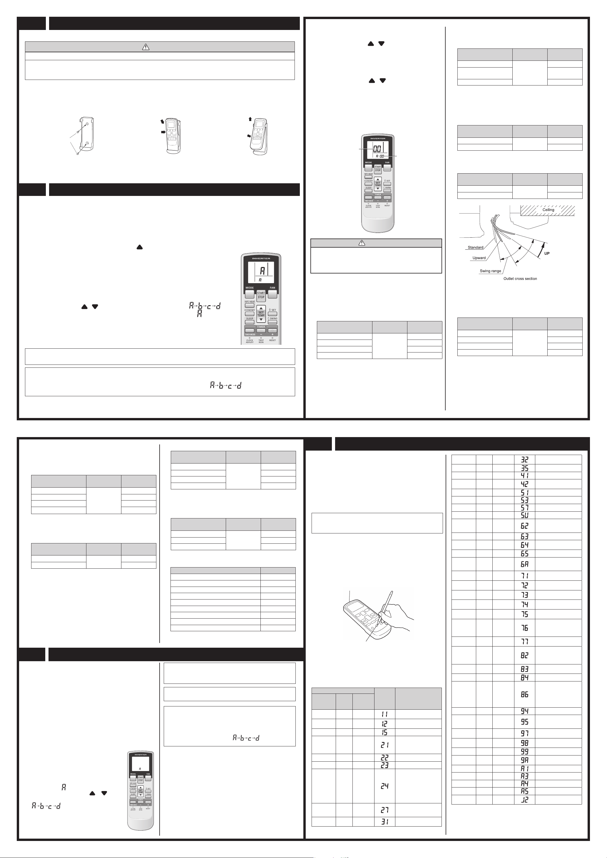
8 TEST RUN
The air conditioner signal code is set toA prior to ship-
ment. Contact your retailer to change the signal code.
The remote controller resets to signal codeA when the
batteriesintheremotecontrollerarereplaced.Ifyouusea
signalcodeotherthansignalcodeA,resetthesignalcode
after replacing the batteries.
Ifyoudonotknowtheairconditionersignalcodesetting,
try each of the signal codes ( ) until you nd
the code which operates the air conditioner.
When two or more air conditioners are installed in a room and
the remote controller is operating an air conditioner other than
theoneyouwishtoset,changethesignalcodeoftheremote
controller to operate only the air conditioner you wish to set (four
selections possible).
When two or more air conditioners are installed in a room,
please contact your retailer to set the individual air conditioner
signal codes.
• Conrmthesettingoftheremotecontrollersignalcodeand
the printed circuit board setting.
If these are not conrmed, the remote controller cannot be
used to operate for the air conditioner.
Selecting the Remote Controller Signal Code
Use the following steps to select the signal code of the remote
controller. (Note that the air conditioner cannot
receive a signal code if the air conditioner has
not been set for the signal code.)
① Press the START/STOP button until only
the clock is displayed on the remote con-
troller display.
② PresstheMODEbuttonforatleast five
seconds to display the current signal code
(initially set to ).
③Press the SET TEMP. ( ) ( ) but-
ton to change the signal code between
.
Match the code on the display to the air
conditioner signal code.
④ PresstheMODEbuttonagaintoreturnto
the clock display. The signal code will be
changed.
7 SELECTING THE REMOTE CONTROLLER SIGNAL CODE
6 FUNCTION SETTING
• Thisprocedurechangestothefunctionsettingsusedtocontroltheindoorunitaccordingtotheinstallationconditions.Incorrect
settings can cause the indoor unit malfunction.
• After the power is turned on, perform the “FUNCTION SETTING” according to the installation conditions using the remote
controller.
• Thesettingsmaybeselectedbetweenthefollowingtwo:FunctionNumberorSettingValue.
• Settingswillnotbechangedifinvalidnumbersorsettingvaluesareselected.
Entering the Function Setting Mode
• While pressing the FAN button and SETTEMP. ( ) simultaneously, press the RESET button to enter the function setting
mode.
STEP 1
Setting the Remote Controller Signal Code
Use the following steps to select the signal code of the remote controller. (Note that the air con-
ditioner cannot receive a signal code if the air conditioner has not been set for the signal code.)
The signal codes that are set through this process are applicable only to the signals in the
FUNCTIONSETTING.Fordetailsonhowtosetthesignalcodesthroughthenormalprocess,
refertoSELECTINGTHEREMOTECONTROLLERSIGNALCODE.
①Press the SET TEMP. ( ) ( ) button to change the signal code between .
Match the code on the display to the air conditioner signal code. (initially set to )
(Ifthe signal codedoes not needto be selected, press theMODE button andproceed to
STEP 2.)
② PresstheTIMERMODEbuttonandcheckthattheindoorunitcanreceivesignalsatthedis-
played signal code.
③ PresstheMODEbuttontoacceptthesignalcode,andproceedtoSTEP2.
TheairconditionersignalcodeissettoApriortoshipment.
Contact your retailer to change the signal code.
Theremotecontrollerresets tosignalcodeAwhenthe batteriesintheremote controller arereplaced.Ifyou useasignal
codeotherthansignalcodeA,resetthesignalcodeafterreplacingthebatteries.
Ifyoudonotknowtheairconditionersignalcodesetting,tryeachofthesignalcodes( )untilyoundthecode
which operates the air conditioner.
Heating room temperature correction
Dependingontheinstalledenvironment,theroomtemperature
sensor may require a correction.
The settings may be changed as shown in the table below.
(◆... Factory setting)
Setting description Function
number Setting value
◆Standard
31
00
Lower control 01
Slightly warmer control 02
Warmer control 03
Auto restart
Enable or disable automatic system restart after a power
outage.
(◆... Factory setting)
Setting description Function
number Setting value
◆Yes 40 00
No 01
*Autorestartisanemergencyfunctionsuchasforpower
failureetc.Donotstartandstoptheindoorunitbythis
function in normal operation. Be sure to operate by the
controlunit,orexternalinputdevice.
Wireless remote controller signal code
ChangetheindoorunitSignalCode,dependingonthewireless
remote controllers.
Ifnobuttonsarepressedwithin30secondsafterthesignal
codeisdisplayed,thesystemreturnstotheoriginalclock
display.Inthiscase,startagainfromstep1.
●(3) ●(2) ◊ IndoorunitPCBmodel
information error
●(3) ●(5) ◊ Manual auto switch error
●(4) ●(1) ◊ Inletairtemp.sensorerror
●(4) ●(2) ◊ IndoorunitHeatEx.
Middle temp. sensor error
●(5) ●(1) ◊ Indoorunitfanmotorerror
●(5) ●(3) ◊ Drainpumperror
●(5) ●(7) ◊ Dampererror
●(5) ●(15) ◊ Indooruniterror
●(6) ●(2) ◊
Outdoor unit main PCB
model information error or
communication error
●(6) ●(3) ◊ Invertererror
●(6) ●(4) ◊ Activeltererror,PFC
circuit error
●(6) ●(5) ◊ Trip terminal L error
●(6) ●(10) ◊
DisplayPCB
microcomputers
communication error
●(7) ●(1) ◊ Dischargetemp.sensor
error
●(7) ●(2) ◊ Compressor temp. sensor
error
●(7) ●(3) ◊ Outdoor unit Heat Ex.
liquid temp. sensor error
●(7) ●(4) ◊ Outdoor temp. sensor
error
●(7) ●(5) ◊ SuctionGastemp.sensor
error
●(7) ●(6) ◊
•2-wayvalvetemp.
sensor error
•3-wayvalvetemp.
sensor error
●(7) ●(7) ◊ Heat sink temp. sensor
error
●(8) ●(2) ◊
•Sub-coolHeatEx.gas
inlet temp. sensor error
•Sub-coolHeatEx.gas
outlet temp. sensor error
●(8) ●(3) ◊ Liquid pipe temp. sensor
error
●(8) ●(4) ◊ Current sensor error
●(8) ●(6) ◊
•Dischargepressure
sensor error
•Suctionpressuresensor
error
•Highpressureswitch
error
●(9) ●(4) ◊ Trip detection
●(9) ●(5) ◊
Compressor rotor position
detection error (permanent
stop)
●(9) ●(7) ◊ Outdoor unit fan motor 1
error
●(9) ●(8) ◊ Outdoor unit fan motor 2
error
●(9) ●(9) ◊ 4-way valve error
●(9) ●(10) ◊ Coil (expansion valve )
error
●(10) ●(1) ◊ Dischargetemp.error
●(10) ●(3) ◊ Compressor temp. error
●(10) ●(4) ◊ High pressure error
●(10) ●(5) ◊ Low pressure error
●(13) ●(2) ◊ Branch boxes error
[Flexible Multi]
Displaymode●:0.5sON/0.5sOFF
◊:0.1sON/0.1sOFF
():Numberofashing
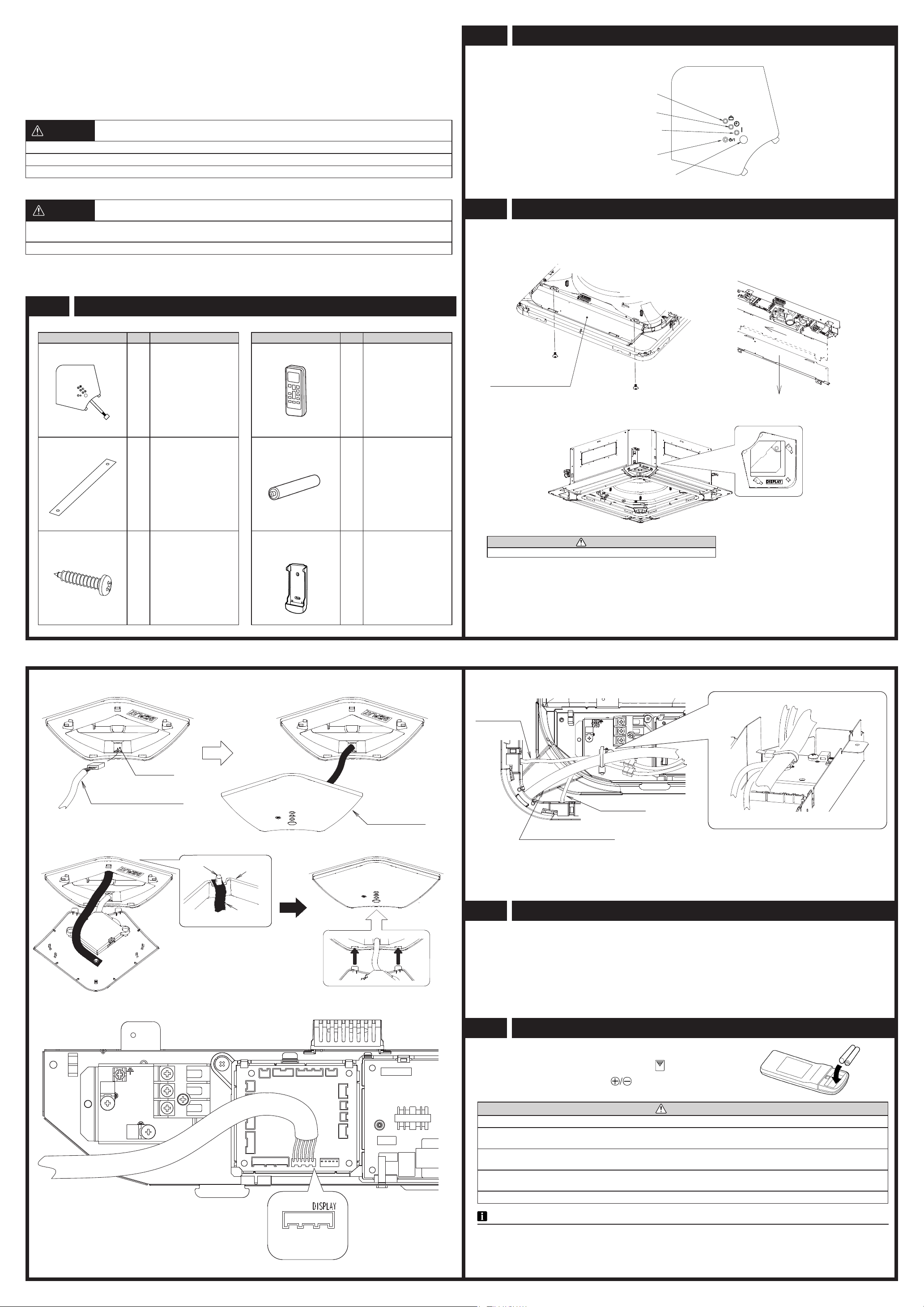
5 REMOTE CONTROLLER SETTING
2. REMOTE CONTROLLER HOLDER INSTALLATION
CAUTION
①Checkthattheindoorunitcorrectlyreceivesthesignalfromtheremotecontroller,theninstalltheremotecontrollerholder.
② Selecttheremotecontrollerholderselectionsitebypayingcarefulattentiontothefollowing:
Avoidplacesindirectsunlight.
Selectaplacethatwillnotbeaffectedbytheheatfromastove,etc.
• Installtheremotecontrollerwithadistanceof7mbetweentheremotecontrollerandthesignalreceiverasthecriteria.How-
ever,wheninstallingtheremotecontroller,checkthatitoperatespositively.
• Installtheremotecontrollerholdertoawall,pillar,etc.withthetappingscrew
①Mount the Holder. ②Set the remote controller. ③To remove the remote controller
(when use at hand).
Screws
Insert
Press in
Slide up
Pull out
Ceiling height
Select the setting values in the table below according to the
height of the ceiling.
(◆... Factory setting)
Setting description Function
number Setting value
◆Standard (3.2m)
20
00
High ceiling (4.2m)
(30model:3.6m) 01
Lowceiling(2.7m) 02
Theceilingheightvaluesareforthe4-wayoutlet.Donot
change this setting in the 3-way outlet mode.
Outlet directions
Select the setting values in the table below for using a 3-way
outlet.
(◆... Factory setting)
Setting description Function
number Setting value
◆4-way 22 00
3-way 01
Vertical direction adjusting scope
Topreventfromdraft,werecommendusing“upwardmode”.
(◆... Factory setting)
Setting description Function
number Setting value
◆Standard 23 00
Upward 01
Cooling room temperature correction
Dependingontheinstalledenvironment,theroomtempera-
ture sensor may require a correction.
The settings may be selected as shown in the table below.
(◆... Factory setting)
Setting description Function
number Setting value
◆Standard
30
00
Slightly lower control 01
Lower control 02
Warmer control 03
(◆.. Factory setting)
Setting description Function
number Setting value
◆A
44
00
B01
C02
D 03
External input control
“Operation/Stop”modeor“Forcedstop”modecanbe
selected.
(◆.. Factory setting)
Setting description Function
number Setting value
◆Operation/Stopmode
46
00
(Setting forbidden) 01
Forced stop mode 02
Setting record
•Recordanychangestothesettingsinthefollowingtable.
Setting Setting value
(1) Filter sign
(2) Ceiling height
(3) Outlet directions
(4)Verticaldirectionadjustingscope
(5)Coolerroomtemperaturecorrection
(6)Heaterroomtemperaturecorrection
(7)Autorestart
(8)Wirelessremotecontrollersignalcode
(9)Externalinputcontrol
AftercompletingtheFUNCTIONSETTING,besuretoturnoff
the power and turn it on again.
UTY-LRHYA2_0521.indd 2 2012/05/21 14:35:07