Fukuda FRE-203XT User manual

1
FRE-203XT
INSTRUCTIONS
from Laser Levels Online www.laser-level.co.uk Tel: 08000 869 769
Thank you for purchasing the FRE-203XT TRUE GRADE Rotary laser level kit.
These Instructions are intended to explain the quick basics to operating this
equipment. We also include with this kit a useful data sheet: “Gradient
Conversion Chart” to convert gradients to percentage grade.
If you need any more help/advice or the instrument requires calibration or
repair, then please contact our Service Dept on tel. 01246 260 007.
We would be pleased to help.
Power source:
This laser level has a special battery pack located in the base. Removal &
refitting is via a central screw - its finger tight, so no tools are required.
The battery contains 4pc x "sealed for life" Ni-MH type C, 4000mAh, 1.2V
cells. Please note that this battery pack can be charged either in or outside of
the laser.
The UK mains Charger (supplied) will charge most batteries in around 7 hours
to give around 20hrs of continuous use. It takes 4 to 5 charge/discharge
cycles for the battery pack to reach its maximum capacity.
Mains Charger:
The general procedure to adopt is use the laser during the day & charge-up
overnight. You cannot damage the laser by "over-charging" the batteries.
Plug the charger into a UK mains supply & the red LED flashes every 1 sec.
Connect to the front mounted socket on the laser (or direct to the battery
pack) & this LED should be ON continuously:
ie. Red LED = charging; Green LED = sufficient charge to operate the laser.
Even though the Green LED is ON, we recommend a full 6-8 hour charge.

2
The FRE-203XT can be operated with the charger connected to the mains
supply, if required, as long as site conditions permit.
On receipt of your new laser, we suggest charging the batteries fully for 6 to 8
hours.
A spare Battery Holder is also included in the kit, to be used as a back-up
power source. Its fitted with four type C, 1.5V Alkaline batteries which can be
used instead of the rechargeable battery or in an emergency; but NEVER
attempt to recharge them, otherwise serious damage will occur.
Positioning the Laser:
Mount the FRE-203XT on a generally level, firm surface or 5/8” threaded
tripod.
To operate correctly, this surface must be within +/-5 deg of true horizontal.
The laser is waterproof, so it can be used Indoors or Outdoors.
Controls:
Power ON/OFF is via the green button. The LCD screen illuminates; laser
takes 15 to 20 seconds to auto level & then the head rotates at 600rpm &
projects a visible red laser beam. The rotational speed is shown on the display
together with the battery charge level.
The yellow speed control button (just above the green button), when pressed,
stops the red dot then increases the head's rotational speed in 4 steps up to a
maximum speed of 600rpm.
For Interior work we suggest using slower speeds, where the laser beam is
easier to see by eye; but for Exterior Groundworks – run the FRE-203XT @ its
maximum speed of 600rpm, which gives the best working range when used
with the supplied FRD400R Laser Detector.
SCAN function - for Interior work:
The second button up on the right of the keypad is the Scan function. The
User can set a static dot, or 10, 45, 90, 180 degree lines as required & use
the two buttons above to move the "laser line" position around the room.
AS THIS LASER AUTO LEVELS BOTH HORIZONTALLY & VERTICALLY,
all the control settings described above operate in either mode.
Grading:
This is a TRUE DUAL GRADE laser level. This means that the FRE-203XT can
be switched to "Manual" (red button "G" to over-ride the level sensors) and

3
then it is very easy for the User to set a grade (incline/slope) in the X axis
only, Y axis only or both together.
The max. settable slope range is +/- 10.00% ie. 1:10
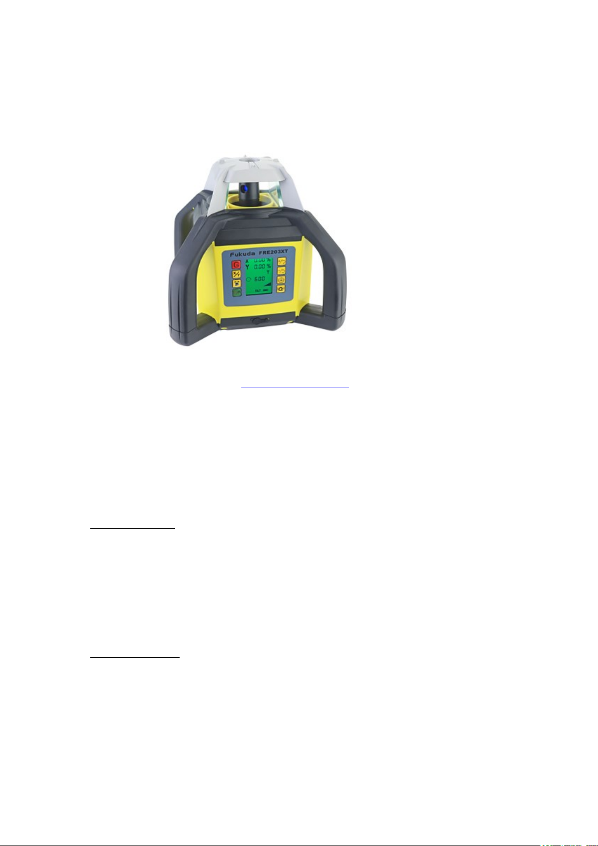
For X & Y alignment, please see the embossed markings on the TOP of the
laser body, where an arrow points in the direction of the axis being set.
Setting a single axis slope - This sets a grade in the X axis.
Procedure – switch ON; the FRE-203XT then auto levels. Press the red "G"
button on the Remote Control or laser's keypad & the "X" axis flashes on the
screen. Using the + or - buttons, set the % gradient value required.
The same buttons can be found on the Remote Control. Press the X/Y button
TWICE and the laser will adjust to this angle of slope, then rotate.
To return to Auto level, switch the laser OFF & ON again via the green button,
to reset the % values to zero. The Laser will wait to find true level, then
automatically restart, self levelled.
Setting Y axis slope - This sets a grade in the Y axis.
Procedure – switch ON; the FRE-203XT then auto levels. Press the red "G"
button on the Remote Control or laser's keypad & the "X" illuminates on the
screen.
Press the X/Y button ONCE only to scroll down to a flashing "Y". Using the +
or - buttons, set the % gradient value required.
The same buttons can be found on the Remote Control. Press X/Y button
ONCE again and the laser will adjust to this angle of slope, then rotate.
To return to Auto level, switch the laser OFF & ON again via the green button,
to reset the % values to zero. The Laser will wait to find true level, then
automatically restart, self levelled.
Setting both X & Y axis slope (dual grade) -
Proceed as above, but enter values for both X% & Y%
MANUAL Grading:
The USER has the option of operating the FRE-203XT in Manual grading
mode, as follows:
1. Mount the laser on a firm surface, switched OFF.
2. Observe the symbols on the green power button. Normal operation is a
single press - for TRUE grade use. The "Hand" symbol denotes MANUAL
grading.
3. Press and hold the green power "Hand" button for 3-5 secs. A "Hand"
symbol is shown on the display & the laser rotates. To switch MANUAL
operation OFF - a single press of the green button is required.
4. With the "Hand" symbol ON, press X/Y button once – “X” is shown on the
display. (Also note the X & Y direction markings on the laser's top black
cover.)
5. Press either the + or - buttons to tilt (grade) the spinning beam, manually,
in the “X” axis.
6. Press the X/Y button again, if you require grading in the “Y” axis as
well. The FRE-203XT can single or dual grade, as required.
7. Expect to grade to at least 1m over a distance of 10m ie. 1 in 10 or 10%.
8. To revert back to normal operation, press the green button again. The
“Hand” symbol goes off.

4
9. Please note, in normal TRUE grade operation, the USER can change to
MANUAL, again by simply pressing and holding the green button for 3-5 secs.
Automatic Drift System (ADS) / often called a Bump sensor:
Operated via the bottom, right-hand button, showing a "picture of a tilted
instrument". nb. its not an option found on the Remote Control.
Once the FRE-203XT is ON and rotating in the auto (self) levelled mode, the
automatic drift system can be activated. Press the button & TILT will be
displayed on the screen. ADS is now active.
If the Laser is knocked or caught by a gust of wind for example, the laser
head will stop rotating and an audible alarm sound to warn the User of the
problem.
Check all is OK, press the ADS button again & the laser will reset back to
AUTO level.
IMPORTANT NOTE: The ADS function cannot be set when Grading.
RADIO Remote Control
& Laser Detector:
Radio Remote Control...
Fit the supplied 2pc x AAA alkaline batteries, taking care with correct polarity.
Switch ON. The LCD shows rotational speed, auto level & battery life.
The Remote’s keypad can set the following functions:
1. Rotating speed in increments: slow for Indoors, fast (max) for Outdoors.
2. Scan angles & position around the room.
3. Auto / Manual (grade) setting via the red "G" button.
4. X/Y button to set required grade axis, then +/- button to adjust the %
value.
Advice: It is often better and more convenient to use the Remote Control
rather than the instrument's keypad, because then, you do not disturb the
laser's sensitive mechanism.
FRD400R Detector...
Fit the supplied 9V battery, polarity marked. Power-up via the ON/OFF button.
The middle button switches the sounder ON or OFF, & volume - if required.
The right hand button sets the red pick-up window’s resolution: coarse setting
(+/-2mm) or fine setting (+/-1mm).
A rear LCD simply repeats the main front display.
Note, the set-level case markings & notches.
You can use the detector with or without its staff mounting bracket.

5
Detector Procedure – face red window towards the rotating laser & "find"
the laser beam via the pick-up window.
If the sun is low in the sky & shining into the red window, shield it with a
cupped hand to prevent false readings. Positioning the FRE-203XT itself in full
sun is no problem, but the detector window can in some instances, be
affected by direct bright sunlight or reflections. So please take extra care!
SAFETY PRECAUTIONS:
Comply with class 2 laser operating safety procedures.
Display a Laser Safety Notice in the work area.
General Advice:
This is an accurate measuring device - so to give good service, look after it!
Prevent the FRE-203XT from receiving severe knocks, bangs or vibration.
Store the laser & its accessories in the supplied carry case.
If wet, dry before storing. Keep in its storage case, OPEN and preferably at
room temperature to prevent condensation forming internally.
It is advisable to remove all batteries before long term storage.
There are NO User Serviceable Parts.
(This would void the warranty)
Aftersales Support:
We offer a full Back-up service including repairs, calibration & usage advice.
Accessories for the various Trades are also available on request.
eg. Tripods, staffs, wall brackets & magnetic machine detectors etc.
Please contact us:
Laser Levels Online, Unit 35 Bridge Business Centre,
Beresford Way, CHESTERFIELD, S41 9FG. England.
Tel: 01246 269777 / Fax: 01246 260007
Laser Levels Online is an internet trading division of P. R Engineering Ltd

6
attached User Data sheets...............
How to set 90 degree SQUARING with a Rotary Laser Level
The following description in this guide, explains the general principles of setting-out
90 degree squaring when using a rotary laser level. It speeds up the classic 3x4x5
triangle method, giving better accuracy and alignment over much longer distances.
This information is intended to be read in conjunction with your laser level’s
Instruction Manual.
Equipment:
You need a rotary laser level which is designed to set “squaring”. It will have an extra
dot beam out of the top of the rotating prism & can be either a red or green beam
laser.
In addition, you will require a matching laser detector (receiver), a target plate and
preferably a remote control. You do not need a tripod nor staff.
(Without a remote control; having another person to assist you, is useful.)
Site Conditions:
There are many different worksite scenarios. As an example, we are assuming that
you have laid a concrete pad or completed your strip foundations (footings) and are
ready to set out in one corner, 90 degree (squaring) for brickwork, blocks or timber
framing, over a datum *mark*.
Procedure:
Place the laser in “lay-down” over your corner datum *mark*, on the concrete surface
& switch ON. Wait for it to auto (self) level, then change to MANUAL. As this
procedure is using “alignment” rather than “levelling” it is more convenient to use the
laser in its Manual mode. See your laser’s User Instructions - if necessary.
Next, remove the bracket from your laser detector. Switch the detector ON and lay it
on its SIDE over a distant mark along one side of the concrete slab or strip footing.
The pick-up window must be facing the rotating beam of the laser level. Using the
remote control, direct the spinning beam to receive a continuous audible tone on the
detector. This has aligned the laser beam exactly on the distant mark.
Next, observe the laser dot projecting from the rotating prism. This is now parallel
with the concrete slab or footings along the other axis. Laser prisms are optically cut
to split one laser beam - to accurately set 90 degrees. ie. Rotating beam in one axis
and laser dot in the other, setting squaring.
The laser dot cannot be picked up with your detector. You need a target plate.
Our recommendation is to use a small piece, say 300mm long white contiplas board,
6- 9 ins wide or similar. Using a black marker pen, draw a vertical line down the
middle of the board. The white surface is an ideal target to “pick-up” the red (or
green) dot at distance, even in bright sunlight. Hold the end face of the target board
down onto the concrete footings, align the dot onto the black line and mark the
concrete accordingly at appropriate intervals. This has set 90 degree squaring.

7
User Tips:
Do not mount the laser level in “lay-down” on a surveying tripod. It must be
positioned directly onto the concrete surface. If mounted on a tripod, it can potentially
introduce an error or inaccuracy to the 90 degree squaring procedure.
Dot axis alignment:
Depending on your make/model of laser level, most have a light house cover over the
prism with glass windows. When setting the laser dot axis, the depth of this cover
(usually around 20-40mm) prevents you from running your line back to the datum
*mark*. So simply mark two positions say 100mm & 1m away from the laser level &
strike a line back under the laser’s cover to the datum *mark* to give the intersection
of both axis.
Fukuda FRE-203X laser level models with Squaring facility:
Applicable models are:
FRE-203XR
FRE-203XG
FRE-203XT
If you have any further questions or need more advice, then please contact our
Technical Team on 08000 869 769.
Laser Levels Online / www.laser-level.co.uk
Other manuals for FRE-203XT
1
Table of contents
Other Fukuda Measuring Instrument manuals