FULL MOON OPTICS OMEGA Series User manual

1
OMEGA Series
O-40
O-55
LONG RANGE THERMAL
CLIP-ON SYSTEMS
OPERATION MANUAL
Version 11.0.30
IMPORTANT: Please read this manual in its
entirety PRIOR to using this device!

2
WARNING:NEVER
POINT THIS DEVICE
DIRECTLY AT THE SUN OR
ANY FIRE / HEAT SOURCE
WITH TEMPERATURE OF
OVER 500C/930F! DOING SO
WILL PERMANENTLY
DAMAGE THE THERMAL SENSOR AND WILL
VOID ANY WARRANTY CLAIMS! SEE PAGE-16
FOR MORE DETAILS AND FOR VERY
IMPORTANT CARE WARNINGS!
THERMAL IMAGING:
Let’s try to understand how this device works and what it can
and cannot do:
1. Your thermal device works on the principle of
detecting infrared radiation, also known as energy.
Instead of operating in a visible light spectrum of 400-
700nm (such as regular binoculars or scopes), thermal
imagers detect waves as high as 17,000nm or 17µm,
which are beyond our capability to observe with naked
eye. The infrared signal is received by the thermal device
and is then converted into an electrical signal by the
thermal sensor (called microbolometer), located inside the
unit and that electrical signal is then displayed on the
micro display located near the ocular (eyepiece).
2. Your device operates with batteries. Unlike a daylight
scope, where you see the image due to light traveling
through the glass and the prisms, the thermal imaging
device works by projecting the image onto a screen.
While the thermal sensor is the crucial component of any
thermal device, the image display quality is also very
important to have the best possible image clarity and
widest field of view. Since the image is projected on the
screen, it has certain limited resolution…so please do not
expect your device to provide the same crystal clear and
full-color image as you would see through your daylight
scope. The main advantage of this thermal device is that it
detects heat signatures in the conditions where seeing
your target is virtually impossible with your naked eye.

3
OPERATION:
OMEGA-40 / OMEGA-55 Thermal Clip-On
13
2
1
9
3
4
5
6
8
7
12
11
10

4
Glossary:
1 –Objective Lens
2 –Objective Lens Protective Cover
3 –Distance Focusing Knob
4 –Video Recording (REC) Button
5 –Table display Button
6 –Image Invert Button
7 –USER Programmable Button
8 –Super Controller / Menu Access
9 –Battery compartment Cover
10 –Micro USB Connection
11 –Eyepiece Assembly Wheel
12 –External Power Connection
13 –Accessory Rail
14 –POWER ON / Standby / OFF Button
15 –Power LED Indicator Light
16 –Eyepiece Lens
INSTALLING THE BATTERIES:
Your thermal device operates on commonly available 3V Lithium
batteries, CR123-type. You need 2 batteries to operate the device.
Rechargeable batteries are OK, but their peak voltage cannot
exceed 4.2V each.
To install the batteries, unscrew the battery compartment cover (9)
until it pops open and install the batteries according to the diagram.
Once the batteries are inside, replace and tighten the cover.
TURNING THE UNIT ON AND OFF:
Your thermal device has a push Power button (14). To turn the unit
ON, first remove the objective lens cover and push the Power Button
(14) for a little over one second. Look through the eyepiece –the
unit will become operational within approximately 4-5 seconds. To
turn the unit OFF push the same button for approximately 2
seconds. Please note that you can enter Standby mode where the
14
15
16
9

5
unit remains on, but the image display is turned off by pressing the
Power Button just momentarily. The red LED power indicator (15)
will remain lit during the standby mode. Always replace the
objective lens cover after the unit is turned off and is no longer is in
use.
FOCUSING THE UNIT:
To obtain the sharp image, you must rotate the Distance Focusing
Knob (3) in either direction, until the image is at its best. You may
have to repeat the process again, until the image is sharp and clear.
SUPER CONTROLLER FUNCTIONS:
Your thermal device comes with a unique Super Controller (8), which
allows for nearly instant image adjustment to the best possible
brightness and clarity without having to enter the menu settings. This
feature is extremely useful when atmospheric conditions change
rapidly, especially during high humidity and/or rapid temperature
changes.
The super controller has the following sequence when short-pressed:
1. IMAGE GAIN (GAIN)
2. DISPLAY BRIGHTNESS (BRGT)
3. SENSITIVITY (SENS)
4. IMAGE DETAIL ENHANCEMENT (IDE)
To adjust the IMAGE GAIN, rotate the Super Controller either
clockwise or counterclockwise while viewing the image –you will
see word GAIN and either positive or negative number appear on
the bottom left corner of the image display. There are 10 negative
and 10 positive Gain levels and a Zero level. Lowering the Image
Gain will allow for better facial and detail recognition. Increasing
the Image Gain will allow for better target detection and
recognition of surroundings, such as houses/buildings, trees and
bushes and so on, allowing you to better see the target
surroundings and to better orient in the terrain.
To adjust the Display Brightness level short-press the
Super Controller once and letters BRGT will appear in the display
–you can now rotate the same switch and Display Brightness will
change. There are 30 levels of display brightness. During
nighttime use, brightness level is optimal between 10 and 20,
depending on the ambient conditions. Keep in mind that higher
brightness levels drain the batteries faster.
To adjust the Thermal Sensitivity (Sensor’s Brightness
Output) short-press the GAIN switch twice and letters SENS will
appear in the display –you can now rotate the same switch and
Sensitivity will change. There are 40 levels of sensitivity (min
sensitivity is 40 and max is 80)

6
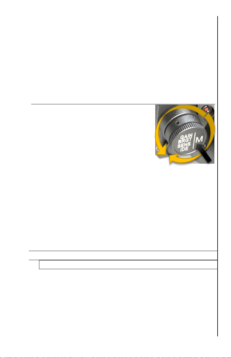
To activate the Image Detail Enhancement (IDE) short-
press the GAIN switch three times and letters IDE will appear in
the display –you can now rotate the same switch and image
details will be enhanced. There are 7 levels of enhancement and
a Zero level. Each IDE level incrementally increases the level of
the detail, similar to the TV resolution upscaling, allowing user to
greatly enhance the image resolution and level of image detail.
This feature is especially useful during high humidity, where
normally level of image detail is poor. It is also useful when
observing object at long distances and when utilizing Zoom
function.
DEVICE MENU NAVIGATION –IMPORTANT!
1. When long-pressed, the Super
Controller activates the main menu
(M).
2. On Once Menu is activated, rotating
controller will highlight each menu
chapter from top to bottom.
3. Once the particular menu chapter is
highlighted in green color, the
selection can be initiated by short-
pressing the Super Controller, after which the menu chapter
will highlight in red color. Now rotate the Super Controller in
either direction to select desired setting. Confirm the setting by
short-pressing the Super Controller, which will change the
highlight from red back to green color. Now the chapter is out
of the selection mode and next menu chapter can be selected
by rotating the Super Controller.
4. Exit back to the main menu by either short-pressing or long-
pressing the Super Controller (depends on the menu function)
5. Main menu can then be turned off by long-pressing the Super
Controller again, or, alternatively the menu automatically turns
off after 15 seconds of inactivity.
Main Menu Selections (from top to bottom):
1. User Profile
There are 3 Custom User Profiles, which can be saved and
deployed when necessary. Each user profile covers variety of
settings, such as Color Palette, type of reticle, color of reticle,
sensor gain and sensitivity, display brightness, Image Detail
Enhancement and other settings. We recommend finding best
settings for a particular terrain or weather conditions and then
saving it as a User Profile, so that next time you are in a
same/similar terrain or weather pattern, you can quickly
activate the settings without having to adjust them all
individually. There are 3 customized User Profiles and 3

7
factory pre-set profiles (Woods, Mountains & City).
Customized profile settings are automatically saved once
adjustments are made and in order to start a new profile enter
the main menu and switch the User Profile from 1 to 2 or 3,
then perform new adjustments according to your preference.
2. Color Palette
This setting allows user to select the image Color Palette.
Please refer to page-12 IMAGE POLARITY INVERSION /
COLOR PALETTES for more information
3. Palette on button “USER”
This menu setting allows you to select which color palette will
turn on when USER button is pressed (this menu option is
only shown when USER button is actually programmed to
switch color palette (see USER Button Function on page-10
for more information))
4. Thermal Image Gain
See page-6 for GAIN adjustment. NOTE: this function is
available via Super Controller and is normally adjusted without
getting into Menu.
5. Display Brightness
See page-6 for BRGT adjustment. NOTE: this function is
available via Super Controller and is normally adjusted without
getting into Menu.
6. Thermal Sensitivity
See page-6 for SENS adjustment. NOTE: this function is
available via Super Controller and is normally adjusted without
getting into Menu.
7. Image Detail Enhancement (IDE)
See page-6 for IDE adjustment. NOTE: this function is
available via Super Controller and is normally adjusted without
getting into Menu.
8. Image Polarity Inversion
See page-13 for IMAGE POLARITY INVERSION. NOTE: this
function is available via INVERT Button (14) and is normally
done without getting into Menu.
9. Super Contrast Display Mode
This setting allows user to enter the Super Contrast mode,
which is helpful during extremely humid weather conditions,
where targets will appear “washed out” against the
background, as well as during the situations where target heat
is waning. This is especially useful during search and rescue
operations where quick location of the heat source may be
very important, as well as when tracking wounded or expired
game. Please note that Super Contrast Mode is only seen on
the scope’ image display, therefore, if you are recording video

8
in the Super Contrast Mode, during video recording playback
only normal mode will be visible. Super Contrast Mode can be
utilized with any of the 10 color palettes.
10. USB Transfer Mode
This setting allows you to transfer the video recorded data
through USB connection to your computer or tablet. Enter this
selection by short-pressing the Super Controller. Please note
that this mode disables most of the scope functions in order to
allow the most reliable USB connection. See more details on
page-17
11. Video Recording Mode (Video Start Mode)
This setting allows you to select how soon video recording
starts. There are two options:
1. Normal start –the video recording module is completely
off until you press REC button (11), then the module
starts, taking approximately 15-20sec between pressing
the REC button and actual start of video recording. This
mode allows you to save the batteries when video
recording is not desired, such as simple terrain orientation.
2. Quick start –the video recording module starts as soon
as you power the scope and enters the standby mode.
When REC button is pressed, video recording starts within
5 seconds during the first recording and within 3 seconds
thereafter. This mode allows you to start recording almost
instantly and is useful when frequent shots are taken
during hunt, or any time when video recording is
frequently used. Please note during this mode additional
battery power is used.
12. Date and Time Stamp Position
This setting allows user to select the on-screen position of the
date and time during video recording. Four positions are
available: Right Down –Left Down –Right Up –Left Up in
addition OFF position is available, which removes date/Time
Stamp from video recordings.
13. Auto Bad Pixel Correction
This function allows the scope computer to automatically
correct any bad pixel. Please refer to the IMPORTANT bad
pixel correction instructions on page-17.
14. Manual Bad Pixel Correction
This function allows the user to correct any bad pixel that may
appear during the use of the device, without having to return
the scope to the factory. Please see page-17 for IMPORTANT
bad pixel correction instructions
15. “USER” Button Function
This unique function allows user to select which function the
User Button (12) can control instantly. You may choose to

9
assign a number of functions to this button, for example
changing the User Profiles, or type of aiming mark (reticle) or
changing the color of the reticle, or assigning a Super Contrast
Mode, or instantly changing the color palette. You may assign
the function to this button at any time and there are no limits to
the number of times the user can re-assign this function.
16. Status Bar Position
This setting allows user to select where on screen the status
bar is displayed. Two positions are available: Up and Down
17. Status Bar Delay Time, s
This setting allows user to select whether the status bar can
remain visible constantly, or will be turned off after a short
delay. Delay time is available between 2 and 7 seconds (in 1
second increments), as well as OFF position, which allows the
status bar to remain visible constantly. NOTE: scope is
shipped with status bar hide time in OFF position.
18. Menu Position
This setting allows user to select on screen display menu
position. 3 settings are available: Up / Center / Down
19. OSD Transparency
This setting allows user to select the transparency of the On
Screen Display Menu, as well as reticle and status bar
transparency. 5 levels of transparency are available along with
Zero transparency. Each higher level of transparency makes
menu more transparent when activated. Higher levels of
transparency prevent developing burn marks, common
with OLED displays, when used over a long period of
time. We recommend setting transparency level on 3 or
higher to maximize the longevity of the OLED display.
20. Auto Power OFF, minutes
This setting allows the scope to automatically power down
after a certain time of inactivity. Default setting is OFF,
meaning the scope will continue to work until manually shut
down, however you can choose an option when the scope will
power down by itself if you have not pressed any button
between 10 minutes and 60 minutes (in 10 minute
increments). This feature is automatically disabled when
active video-recording is in process.
21. Position Profile
This setting allows user to save up to 5 paired daylight scopes
when using device as a clip-on. Profile is saved automatically,
so when pairing to a different riflescope, you must switch
profile from 1 to 2 (from 2 to 3 and so on) in order to keep the
previous profile settings. Short press of Super Controller (8) to
highlight the function and rotate the controller to choose profile
number. Once finished, exit the menu.

10
22. Image Position Correction
This setting allows user to adjust the thermal image up/down
and left/right in the clip-on mode, in order for the thermal
display to be positioned in the center of the daylight scope.
Short press of Super Controller (8) changes between vertical
and horizontal adjustments and rotating the Super Controller
adjusts the position. Once finished, exit the menu and settings
are automatically saved.
23. Table Position Correction
This setting allows user to adjust the Table menu position in
relation to the image viewed through the daylight scope,
allowing the table to be positioned either in the center of the
view, or away in any of the corners, as you prefer. Short press
of Super Controller (8) changes between vertical and
horizontal adjustments and rotating the Super Controller
adjusts the position. Once finished, exit the menu and settings
are automatically saved.
24. Restore Position Settings
This setting allows user to reset the image and table positions
to the factory settings.
25. Date Set
This setting allows user to set the date, as it would appear on
the video recording stamp. The date appears in YYYY-MM-DD
sequence. Rotate the Super Controller to change the year,
then switch to month by short-pressing the Super Controller
and repeat the same for day. Once day is adjusted, short-
pressing the Controller returns to the main menu.
26. Time Set
This setting allows the user to set the time, as it would appear
on the video recording stamp. Switch between HH:MM:SS by
short-pressing the Super Controller and adjust the time by
rotating the Super Controller. Please note the time is
displayed in military units, so 1pm = 13:00, 6pm = 18:00,
11pm = 23:00 and so on.
27. Clear Video Record Storage
This selection allows you to format the memory card and
erase all video recordings from the card without connecting
device to the computer. To protect from accidental erase,
once this feature is selected, the device will ask you to confirm
this selection within 5 seconds by short-pressing the Menu
button, otherwise the function will not activate.
28. Language
This setting allows user to select menu language. 4 languages
are available: ENGLISH –GERMAN –SPANISH –RUSSIAN
29. Software Version

11
This selection displays the current software version and
cannot be edited. This information may become useful if
customer support is required.
30. Settings Reset
This selection allows user to reset all settings to factory levels.
We do not recommend using this function, unless you feel that
the scope is not functioning as it should. If this happens and
you need to reset the settings to factory levels and after the
reset you have any troubles navigating the menu, please e-
2721 with any questions you may have.
IMAGE POLARITY INVERSION / COLOR PALETTES:
It is possible to change the way the heat signatures are displayed –
the default image is “WHITE HOT” meaning the heat signatures will
appear in white or light color with most of the background appearing in
black or dark color. You may switch (invert) this setting by pressing
the INVERT Button (6) once and then heat signatures will appear in
dark color “BLACK HOT” on otherwise light color background. In
addition, the unit also has options of 10 color palettes, each with invert
option, which highlight heat signatures in various colors. To change
between the Color Palettes, long-press the Super Controller (8) to
enter main menu, then rotate Super Controller until word “Palette” is
highlighted. Then short-press Super Controller to select this function
and then rotate the Super Controller to switch between various Color
Palettes. There are 9 color palettes + default black & white mode. You
should try each color setting to see which one renders images best
during various atmospheric conditions and humidity levels, as well as
for the particular task at hand. Once finished selecting the color
palette, short-press the Super Controller to return to the main menu
and then long-press the same Controller to exit the menu. Your color
and invert setting is automatically saved and will appear next time you
turn on the device.
USB & EXTERNAL POWER SUPPLY:
It is possible to connect an optional external 5V power supply to the device
through the micro-USB connector (10) in order to operate it for a longer
periods of time. The external power supply could be a common battery
power pack, used to charge and operate your cell-phone and can be
purchased on Amazon, or at local electronics retailer. Please make sure
only 5V power supply is used and output power on the utilized USB port
should be at least 2A. To connect an external power supply, remove the
safety cap by unscrewing it counter-clockwise and either connect the
micro-USB cable directly into the input, or (IF SUPPLIED WITH FACTORY
USB ADAPTER CAP AND CABLE) screw in the USB adapter cap and
then connect the micro-USB side of the factory cable into the factory USB
adapter and then connect the normal USB side of the factory cable into the

12
USB output of your power supply. Once the external power supply is no
longer needed, remove the factory cable and also remove the USB adapter
and replace the metal safety cap before you take the unit to the field. Store
the factory USB adapter and factory USB cable together in the carry case.
VIDEO RECORDING:
Please see page-8 for video recording start options (Normal Mode
and Quick Mode)
To start video recording, press REC button (4) once. Depending on the
chosen recording mode the actual recording will start anywhere between 3
and 15 seconds from the moment the REC button is pressed. Once the
counter starts the actual recording begins.
To stop recording press REC button again once. Words “REC Saving” will
appear momentarily in the display –this is your indication that video
recording has been successful and is saving on your scope’internal hard
drive.
Should you encounter any error during recording, message ERR will
appear with a number next to it (example ERR-74). If this happens it may
be due to recoil issue or possibly batteries discharge. In the case of any
ERR message press REC button once and it will exit the ERR mode and
then you can re-start recording by pressing REC button again. If ERR
message keeps re-appearing, please call us at 478-954-2721 or e-mail us
at FullMoonOptics@gmail.com.
BAD PIXEL CORRECTION:
IMPORTANT: DURING ANY BAD PIXEL CORRECTION PROCESS YOU
MUST KEEP THE LENS COVER ON AT ALL TIMES AND WE RECOMMEND
PLACING A DARK TAPE OVER THE PINHOLE IN THE LENS COVER. THIS IS
NECESSARY FOR A COMPLETELY UNIFORM DARK SCREEN DURING THE
PROCEDURE.
Your device comes with a unique feature allowing you to manually correct
any bad pixels that may develop during the course of time. To do that,
press and hold Super Controller (8) to enter the main menu. Then rotate
the Super Controller counter-clockwise until “Bad Pixel Correction” is
highlighted. Then short-press the Super Controller to enter the pixel
correction mode. The white crosshairs with flashing dot in the center will
be displayed. Now you can rotate the Super Controller to direct the
flashing dot to the bad pixel (to change between horizontal movement and
vertical movement short-press the Super Controller. Once the flashing dot
is over the bad pixel, press Table button (5) and bad pixel will be
corrected. You may need to press Table button more than once. Should
you have a bad spot larger than one pixel, you must work each pixel one
at a time, starting from outside pixels and then moving to the inside pixels.
After all bad pixels are corrected, long-press the Super Controller until it

13
enters Main Menu. NOTE: if you do not perform this function, bad pixel
corrections will not be saved and you will have to perform the corrections
again next time you start the scope. NOTE: latest models come with
Automatic Bad Pixel Correction function, which does the process
automatically.
USB TRANSFER MODE: Please read carefully!
1. Power the scope.
2. Enter the main menu and select “USB Transfer Mode” (see also page-
8) –USB Transfer Mode turns OFF all other functions of the
scope –it should only be used during actual data transfer.
3. Remove the Micro-USB Connector cover (10).
4. Connect the micro-USB side of the cable to the Connector output. We
recommend using short length USB cable and if possible a
USB3.0 cable for faster and more reliable operation. Take care
during the connection to eliminate possibility of breaking the connector
points. Do not use excessive force when plugging the micro-USB
connector and never try to rock the connector from side to side during
connection –this may break the connector points and render the USB
connection inoperable. NOTE: broken USB connector is not covered
under warranty.
4a. IF SUPPLIED WITH FACTORY USB ADAPTER CAP AND
CABLE use the factory USB adapter cap and the factory cable for this
task.
5. Connect the USB side of the cable to your computer.
6. Once the pop-up window appears, select “Open Files”
7. Transfer any video files you may have.
8. When finished you may keep the files recorded on the scope, or you
may delete them from the scope storage to make space for new
recordings.
9. Always follow the safe connection exit by asking to eject the USB
drive.
10. Turn off device to exit USB Transfer mode
MOUNTING THE DEVICE ONTO A WEAPON AND ALIGNING
THE IMAGE WITH DAYLIGHT SCOPE RETICLE:
Zeroing a thermal clip-on in front of a day optic requires more care and
effort than zeroing a day optic or most light amplification clip-ons (for
example: PVS22/30). Properly done it gives capabilities impossible to
duplicate with day only or light enhanced optical shooting systems.
STEP 1: Shoot a three or five round group with your day scope only
at 100 meters/yards, unless you are absolutely certain of your day
optic zero, in which case you can skip this step. Mark these hits for
later reference.

14
STEP 2: Mount a zeroed rifle as securely as possible in some sort of
rest (the Lead Sled is recommended) and align the crosshairs on a 25
meter/yard (m/y) target. Shoot a round at the 25m/y target. Nudge or
adjust the rifle back to pointing at the aim point. Normally a rifle zeroed
for 200 m/y will shoot an inch or perhaps 1.5” below the point of aim.
Mark the shot with a Magic Marker.
Before mounting the Omega clip-on set the following:
Select Clip-on mode
Select ‘Position Profile’ and set to 1 of 5 positions. (Allows
pairing with up to 5 different rifles/daylight scopes).
Set focus, gain, brightness, sensitivity and Image Detail
Enhancement (IDE) for the clearest target image at 25m/y.
Now (without moving the rifle), it is time to install the Omega clip-on.
If, during installation, you think you may have ‘bumped’ the rifle,
remove the Omega clip-on and confirm or reset daylight optic
alignment with the aim point.)
STEP 3: To mount onto a weapon, you must have a Picatinny Rail on
your gun that is long enough to accept the clip-on in front of your
daylight scope. Attach the included short mount with the two screws
onto the baseplate of the clip-on. Use a little drop of Loctite Blue to
secure the screws if you plan to use the device on one weapon either
permanently or for a very long time. Align the front and rear mounting
plates of the scope mount with the rails, so that clip-on mounting
indents are inside the rails and slightly tighten the screws. NOTE: you
must position your clip-on at such distance where the rubber eyecup
shade is either immediately next to, or actually touching the front lens
barrel of your daylight scope. This is necessary to keep any possible
Point Of Impact shift to a minimum. Ideal distance between the front
lens of your daylight scope and the back lens of your thermal clip-on is
15mm. Once the ideal position is obtained, if you intent on keeping this
clip-on permanently on the gun, we recommend using Loctite blue to
secure the clip-on mounting screws in place.
If mounted correctly, the device should be positioned similar to as
shown below. Note the Rubber eyecup shade alignment with the
daylight scope. It is OK to squeeze the eyecup slightly in order to
make a contact with the daytime scope frame.

15
STEP 4: Attach a small thermal target to the aim point. Be prepared to
freshen (replace) cold targets if they fade. Use the ‘IMAGE POSITION
CORRECTION’ menu to move the crosshairs to the thermal target,
without moving the rifle. Fire a second round. Use ‘IMAGE POSITION
CORRECTION’ menu to make both vertical and horizontal
adjustments to move your 2nd shot toward the 1st shot. To adjust the
bullet strike to the right, rotate the Controller knob clockwise while in
the horizontal part of the menu. To move the bullet strike lower, rotate
the Controller knob clockwise while in the vertical part of the menu.
These adjustments are consistent with the way mechanical turrets
work in the daylight riflescopes. There is no fixed value for the clicks
for a particular setup (it is an electronical algorithm). Make
adjustments, then fire another shot. Based on how far the bullet impact
moved, you can calculate the approximate value of the clicks. Please
keep in mind that the value of the vertical plane clicks may differ
significantly from the value of the horizontal plane clicks.
Mark or make note of your 3rd shot and make additional adjustments
as required.
STEP 5: When your 25m/y bullet strike overlays where your ‘daylight
scope only’ setup shoots, move target to 100 m/y. It is no longer
necessary to use the Lead Sled or bench rest.
Reset focus, gain, brightness, sensitivity and Image detail
Enhancement for the clearest target image at 100m/y.
Fix a new thermal target and shoot a 3 to 5 round group. Make
adjustments as necessary using the ‘IMAGE POSITION
CORRECTION’ menu and shoot an additional group. Repeat as
necessary. You are zeroed when the groups overlay those fired
initially in Step 1 with the ‘day only’ optic.
STEP 6: Set the TABLE POSITION CORRECTION for a quick
reference to proper zero where the crosshair section of the table is
aligned with your daylight scope reticle.
Your Omega clip-on is now zeroed to your particular rifle/optic in the
clip on mode. It is a good idea to write down which rifle/optic is set to
which ‘Position Profile.’ Noting your final ‘IMAGE POSITION
CORRECTION’ settings (for example: -7 horizontal / +43 vertical) may
make starting from scratch easier if you need to go back to ‘square
one’ for any reason.

16
WARNINGS:
1. NEVER point this device
directly at the sun or any heat
source over 500 degrees
Celsius (930 degrees
Fahrenheit) even if the device
is not turned on! Doing so will
permanently damage the
sensor with random light glare
(similar to pictured here). Such damage is not covered by the
warranty and will void any warranty claims. Always have the
protective cover on the scope when transporting it during
daylight, particularly during sunny days! Always transport
your scope during sunny day pointed downwards, especially
when mounted on the weapon.
2. NEVER try to disassemble the unit by yourself or by anyone who
is not our authorized technician. Doing so may result in injury and
will void any warranty claims
3. NEVER leave the batteries inside the unit for a long period of time
during extremely hot temperatures –the batteries may overheat,
which may render the unit inoperable and will void the warranty
4. NEVER submerse the unit into water or use during heavy rain.
TECHNICAL SPECIFICATIONS:
Imaging Sensor______ Hybrid Resolution 17µm with Image Enhancement
Frame Rate ____________________________ 50 Hz Shutter-free / NUC-free
Spectral Response _______________________________________ 8-14µm
Image Display ______________________________ 1,024x768 Micro-OLED
Number Of Color Palettes ______________________________________ 10
Eyepiece _________________________________________________30mm
Focusing Distance___________________________________ 3m (4yds) - ∞
Objective Lens Aperture______________________________40mm (55mm)
Field Of View_________________________________9.3° x 7.0° (7.5° x 5.6°)
Detection range (human)____________________________2,000m (2,800m)
Video Recording Resolution ______________________________ 1024x768
Video File Type _____________________________________________ .AVI
Memory _______________________________________________ SSD 8GB
Maximum impact load _______________________________________ 600g
Power Supply_________________________ 2 x CR123 Lithium / or 5V USB
Working time ___________________________ 3.5-4.5hrs (CR123 batteries)
Working Temperature Range__________________-15C / +50C /// 5F / 122F
Weight (riflescope mode)________________________________570g (600g)
FULL MOON OPTICS
136 Sewell Rd., Elko, GA 31025 (USA)
Tel: +1-478-954-2721 / +1-478-239-0099
E-mail: FullMoonOptics@gmail.com Web: www.fullmoonoptics.com © 2020
This manual suits for next models
2
Table of contents
Other FULL MOON OPTICS Monocular manuals