Fumex ASE 130 User manual
MANUAL
A18W35_MASE 130_F_EN
© Fumex AB, 2017
2
With provision for changes
CONTENTS
1 Idenficaon
1.1 Manufacturer
1.2 Product name
1.3 Year of manufacture
1.4 Area of use
2 Technical specificaon
2.1 Design
2.2 Funcon
2.3 Technical data
2.4 Security
2.4.1 Acvaon
2.4.2 Hazards
3 Preparaon for use
3.1 Transport and storage
3.2 Installaon and assembly
3.2.1 Assembly
3.2.2 Hose selecon
4 Operang instrucons
4.1 Installaon and startup
4.1.1 Before startup
4.1.2 Assembly and operaon
5 Troubleshoong
5.1 Troubleshoong guide
6 Care instrucons
6.1 Acvaon
6.2 Maintenance
6.2.1 Checklist maintenance
7 Details diagram
8 Accessories
PAGE
3
3
3
3
3
3
3
3
4
4
4
4
5
5
5
5
6
6
6
6
6
6
6
6
6
7
7
7
8
Hereaer, the following symbols will refer to:
Safety instrucons (applicable to people or
productry) that must always be adhered to. Risk
of fatality or risk of personal injury or damage to
property are present.
Instrucons that will provide you with important
informaon for an opmally funconing hose reel.

3
1
4
3
2
5
1 Idenficaon
1.1 Manufacturer
Fumex AB
Verkstadsvägen 2
931 61 Skelleeå, Sweden
Tel: +46 (0)910-36180
Email: inf[email protected]
1.2 Product name
ASE 130
1.3 Year of manufacture
2018
1.4 Area of use
Fumex ASE is a hose reel intended for evacuaon of exhaust
gases and prevents obtrusive hoses lying on the floor. The
hose reel takes up lile space and can be mounted on the
ceiling or wall.
Explosive gases must not be removed!
To preserve the validity of the product warranty, it is
forbidden to modify or re-engineer the product during the
warranty period without first obtaining prior approval from
Fumex. This is also applicable to any spare parts used which
do not comply with the manufacturer's specificaons.
Damage that is not due to normal use of the product will
result in:
- the warranty being voided.
2 Technical specificaon
2.1 Design
Exhaust hose reel ASE, see Fig. 1.
ASE consists of brackets (1), beams (2),
duct connecon (3), retractor reel device (4) and hose (5).
2.2 Funcon
The exhaust hose reel is designed for use as a sucon device
for vehicle exhausts.
Contaminated air is sucked into the hose by a separate fan
which is connected to the duct connecon. The hose reel ASE
works with a ratchet. This means pulling out the hose to the
desired locked posion and then when you pull the hose again
it releases the lock.
In the locked posion the spring package is in
full force.
Fig. 1

4
13
200
600
o
o
535
25
1412
1374
520
563
965
1510
200
430
o
Fig. 2
2.4 Safety
2.4.1 Acvaon
The product is safe to use. It is designed in such a way that
hazardous parts only occupy restricted areas. Even so, if the
product is not used correctly or as intended, it may be hazar-
dous to the user or cause damage to the product. The user
should therefore be informed and trained to handle the
product’s safety features.
To minimize work-related accidents and injuries during use,
risk reducon has been carried out as follows:
- built-in safety in the design.
- technical protecon such as barriers, etc.
- informaon for use such as user instrucons and labels, etc.
The product/system may only be used in perfect
technical condion and in accordance with the
user instrucons. Faults that may reduce safety
must be eliminated immediately!
In addion to the user instrucons, naonal and
local safety and accident prevenon regulaons
must be followed when operang the product.
2.4.2 Hazards
Note that moving parts in the system always pose
a risk (e.g. cung, clamping or gripping points).
Hose reel ASE 130
Weight*:......................................... 57 kg
Material cross member: ................. Anodised Aluminium
Material other metal: ..................... Steel
Material inlet bearing:.................... Plasc
Material outer bearing: .................. Plasc
Colour bracket (Grey): .................... NCS S8502-B
Colour end caps (Blue): .................. NCS S7020-R90B
Max. liing power: ......................... 30,5 kg
Max. rolled-up hose (Ø200 mm): ... 11 m
Temperature limits
Operang temperature: ................. +5 to +650 °C**
Ambient temperature: ................... +5 to +50 °C
Transport and storage temp:.......... -20 to +50 °C
* Excluding hose.
** Temperature resistance depends on the hose selecon.
For other temperatures, contact Fumex
2.3 Technical data
5
1
(h)
ASE 130 8 33 9
ASE 130 8 41 11
ASE 130 8 49 12
(h)
6 5
7
3
4
2
Fig. 4
Fig. 5
Fig. 3
3 Preparaon for use
3.1 Transport and storage
Protect the hose reel from rain, snow aggressive
atmospheres and other damaging circuimstances.
3.2 Installaon and assembly
3.2.1 Assembly
Assembly may only be carried out under consideraon of
these assembly instrucons and applicable regulaons.
1. Remove all the packaging from the product and leave it
assembled on the pallet.
Item 2-6 does not apply if the reel has been
ordered complete with hose.
When assembling the hose, ensure that the reel
is blocked correctly. Risk of personal injury.
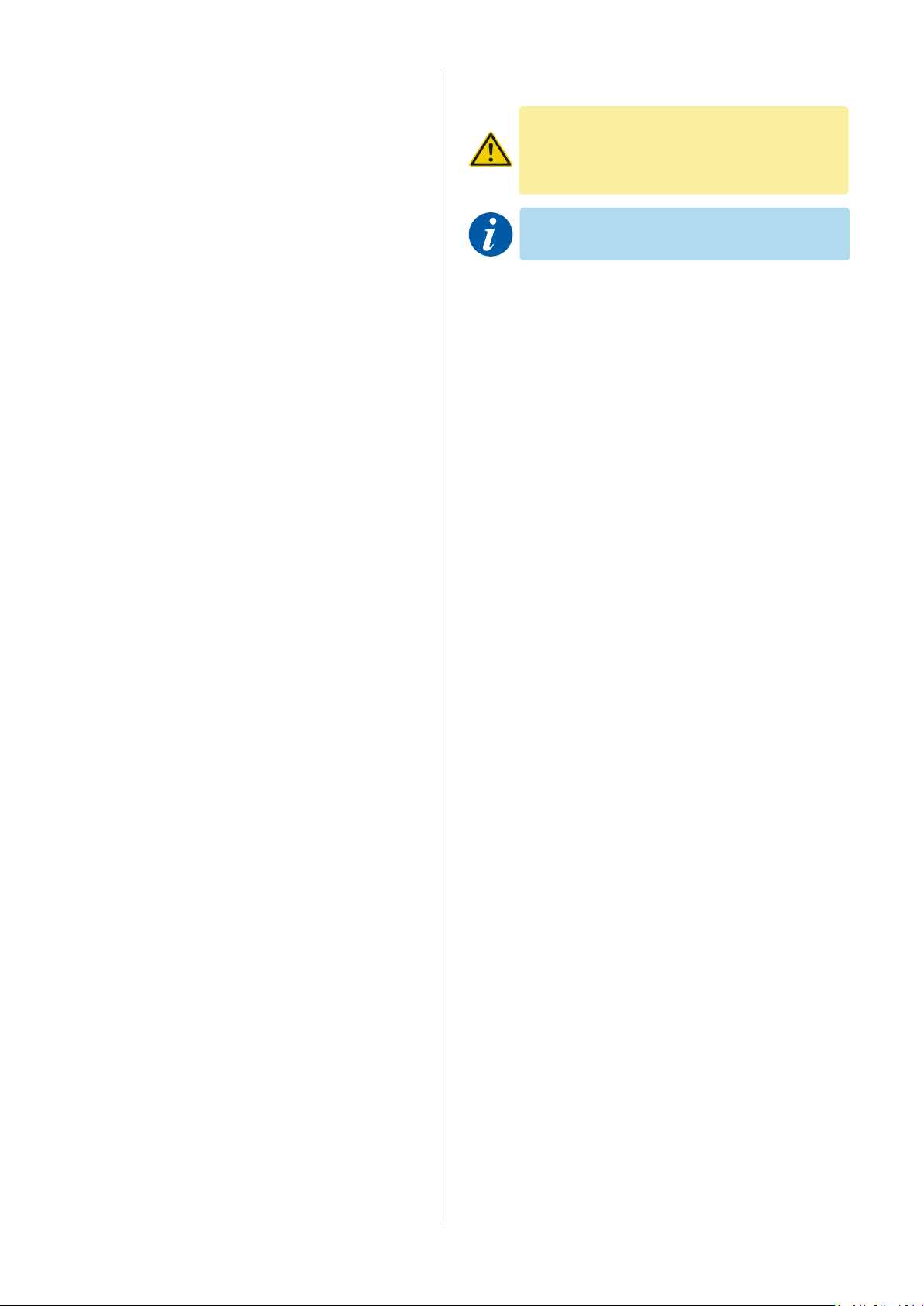
2. Secure the pallet and pre-load the hose reel according
to the table. Turn the drum in the direcon indicated by
the arrow (1, Fig. 3).
3. Remove the hose clamp (2) and rubber sheet (3).
4. Install the hose (5) on the sucon tube (4) using hose
clamps (6).
5. Secure the hose by first placing the rubber cloth (3) around
the hose. Then pull the hose clip (2) through the holes
and around the rubber sheet to lock securely (Fig. 4).
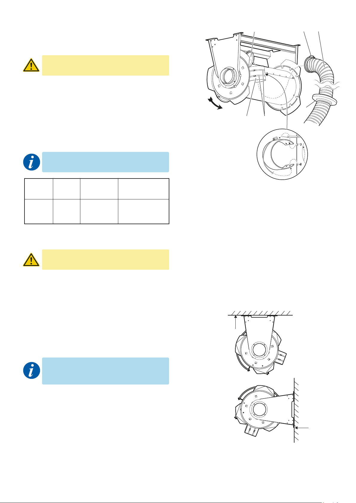
The hose stop should, when in the retracted
posion, rest against the drum and fit between
the end cap and the adjacent hose. Risk of wear.
6. Install the hose stop (7, Fig. 3) in the desired posion.
Release the latch and wind the hose unl it stops against
the hose stop.Check that the hose stop is working and
assembled correctly.
7. Remove the roller from the pallet and install it onto the
ceiling or wall using correctly dimensioned fastening
elements.
Dim. Hose length Bias
Product (mm) (m) (turns)*
* The calculaons only apply when using Fumex original AGX hose,
Fumex 3.2 kg nozzle and an installaon height of 6 metres.
8. Check the roller and the venlaon ducts properly, so
that foreign objects are not present. Remove any such
objects immediately.
9. Seal and install the venlaon ducts directly to the
duct connecon on the roller, or use a hose ASL 200
between the duct and roller (see Accessories).
10. Check that the gaskets and connecons on the roller
and venlaon duct are ght.
11. Install the nozzle.
12. The hose winding reel is ready for use.
Maximum mounng height
- 6 m (h, Fig. 5).

6
Problem
1. The hose does not stop
in the correct posion.
2. Leakage sound in bearing.
Possible cause
Hose stop.
The negave pressure in
the system is too high.
Bearing worn out.
Acons
Adjust the posion of hose stop.
Lower the negave pressure (max. 2500 Pa).
Change bearing.
6 Care Instrucons
6.1 Acvaon
Disrupons caused by lack of or faulty
maintenance may result in high costs for the
product.
The checklist for maintenance is designed for normal use of
the product. The recommended intervals are approximate
and refer to the me aer the first startup. Depending on
the changing operang condions between the different
systems, the intervals for recommended maintenance may
differ. The user should therefore determine their own
maintenance intervals.
Please remember that only original spare parts
may be used.
When replacing damaged fasteners, only those of idencal
quality (strength, material) and type may be used.
3.2.2 Hose selecon
Select the appropriate hose length, see table.
If using your own hose, use accessory AES 200,
a hose stop that meets the safety requirements
for the product.
For informaon relang to AES see 8 Accessories.
Max. rolled-up hose Ø200 mm is 11 metres.
4 Operang instrucons
4.1 Installaon and startup
4.1.1 Before startup
Before startup the device, read the instrucons
provided in chapter 2.4 Safety.
4.1.2 Assembly and operaon
Any faults must be recfied before
operaonal startup.
1. Check that any electrical connecons are correctly
performed.
5 Troubleshoong
5.1 Troubleshoong guide

7
12
1
65
3
2
9
10
4
7
8
11
13
14
15
16
17181920
21
22
23
22
24
Device
Hose reel
Interval
Daily
Every three
months
Every six
months
Item
1.1
1.2
1.3
1.4
1.5
Inspecon module
Hose
Hose connecons
Hose reel
Duct system
Hose reel
Maintenance instrucons
Check that the hose is intact. Replace if necessary.
Check the fastening on hose connecons.
Look for leaks, damage and wear.
Check the dust build-up and clean if necessary.
Clean the roller externally with a damp cloth.
Date
6.3 Maintenance
6.3.1 Checklist maintenance
7 Details diagram
1. Sha extension
2. Spring pile
3. Spacing sleeve
4. Bracket
5. Bearing retainer
6. Guide bearing
7. Locking mechanism
8. Slide bearings
9. Beam
10. Bracket
11. Connecon
12. Ratchet disc
13. End cap
14. Drum
15. Guard
16. Steering hose
17. Bracket
18. Sucon tube
19. Threaded rod
20. Hose clamp**
21. End cap
22. Hose clamp**
23. Protecve cloth**
24. Hose*
* Accessories AGX hose
** Accessories AES 200

ASES 200 ASE 865
AES 200
ASL 200
phone +46 910-361 80 │ fax +46 910-130 22 │ www.fumex.com │ inf[email protected]
8 Accessories
ASES 200 ASE 865
AES 200
ASL 200
Automac mechanical damper.Switches to control the fan/electric dampers.
• 2 x Hose clamps
• 1 x Hose, AGX 200, length ≈ 0,2 m
• 1 x Hose stop
• 1 x Hose clamp for installing the hose
• 2 x Hose clamp for installing the hose stop
Table of contents
Other Fumex Tools manuals


