Functional Fenestration AGB Unitop 1455-3 User manual

FFI Tech Dept. v 09.11.06 Measurements in Millimeters. 1” = 25.4mm 1 of 11
AGB Unitop
®
Model 1455-3 Door Lock
Installation Guide
Unitop® Model 1455-3 Door Lock
3-Point Locking Hardware
All article descriptions and technical specifications herein correspond to the time of publication.
FFI reserves the right to make modifications.
FFI cannot assume liability for errors caused in printing or otherwise.

FFI Tech Dept. v 09.11.06 Measurements in Millimeters. 1” = 25.4mm 2 of 11
AGB Unitop
®
Model 1455-3 Door Lock
Installation Guide
Table of Contents
1.0 Basic Information
1.1 Technical data
2.0 General Description
2.1 Technical characteristics
3.0 Door Preparation
3.1 Lock stile milling
3.2 Lockbox mortise
4.0 Lock Cutting & Mounting
4.1 Lock cutting using standard handle height
4.2 Lock cutting using lowered handle height
4.3 Lock handing
4.4 Lock mounting
5.0 Strikes & Keeps
5.1 Thimble keeps
5.2 Latch and deadbolt strike
6.0 Handle Trim & Profile Cylinder
6.1 Handle trim
6.2 Profile cylinder
7.0 Operation & Maintenance
7.1 Operation
7.2 Warranty
7.3 Maintenance

FFI Tech Dept. v 09.11.06 Measurements in Millimeters. 1” = 25.4mm 3 of 11
AGB Unitop
®
Model 1455-3 Door Lock
Installation Guide
1.0 Basic Information
Congratulations on your purchase of this innovative product from AGB. Unitop® is a registered
trademark of Alban Giacomo spa (AGB). The Unitop door lock complies with EU standards.
The Unitop model 1455-3 door lock can be assembled and installed by experienced personnel
without difficulty by using this installation guide. This shall be verified in the case of complaints.
Arbitrary modifications and changes to the Unitop lock or its accessories are not permitted.
Installation of products that are not original AGB products and the use of parts that have not been
approved by AGB may negatively affect the given design characteristics of the locking device. All
repairs must be conducted by authorized specialists and with original spare parts. The
manufacturer will not accept liability for damages caused by failure to observe these instructions.
This will also void warranty claims in any form.
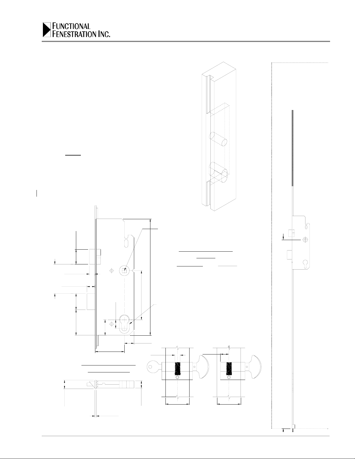
1.1 Technical Data
Type: Lift Lever Operation.
Door Height: min=1800mm; max. =3658mm
Faceplate: width=16 mm; thickness=2.5mm; length=1920 mm + upper shootbolt & extensions.
Lockbox Backsets: 35, 40, 45, 50, & 55mm.
Lockbox Depth: backset + 18mm.
Spindle Size: 8mm square.
Spindle Centers: 92mm.
Handle Height: set at 1050mm (standard); may be lowered to a minimum 948mm.
Shoot-bolt Throw: 15mm
Material: steel.
Finishes: yellow bichromate & silver zinc.
2.0 General Description
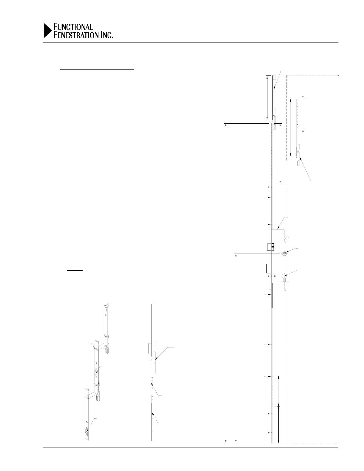
The Unitop Model 1455-3 is a multiple locking device (door lock) for swinging doors. This door
lock is designed for the securing of the “active” (primary) door in a swinging double-door
(“French”) system. This door lock ensures that the active door is securely locked by means of a
central latch & deadbolt that inserts into the inactive door along with two vertical “shoot-bolts”, one
that secures the top of the door to the head jamb and one that secures the bottom of the door to
the sill. A reverse mechanism, contained in the lock case, allows the upper and lower drive rods
to move in opposite directions. The reverse gearbox commonly installed at the end of one rod is
thus eliminated. The locking is more secure and the mechanism is simpler and more practical.
The lock is not handed and is easily reversed with a screwdriver. Its self-adjusting spring latch is
inclined and rounded on both sides. This shape guarantees a perfect closing of the door. An
upward motion of a lever style handle only engages the deadbolt and shoot-bolts.They are
disengaged by downward motion of the handle. The handle may be locked from movement by the
use of a manually activated European lock cylinder (optional).
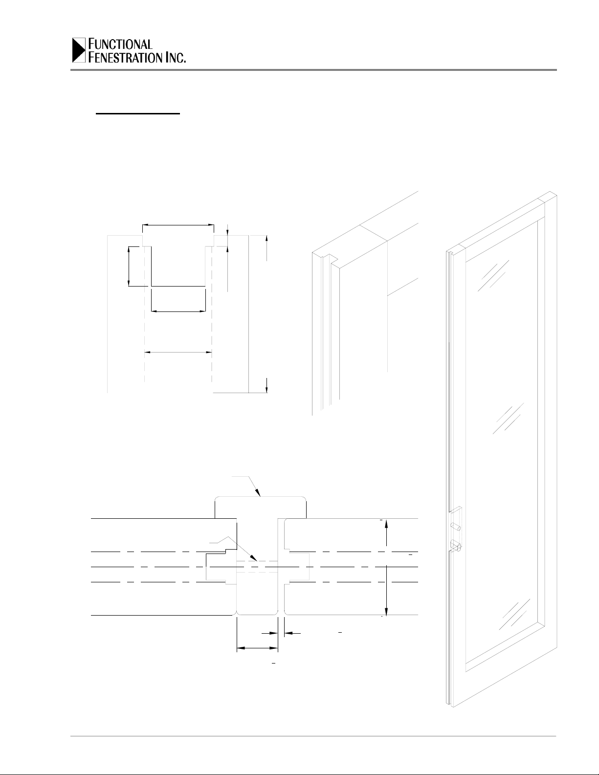
The Unitop lock is suitable for all types of door materials. The door lock-stile must be milled or
equipped with a “Euro” hardware groove for mounting of the locking hardware. The door head
jamb and sill must be able to accept a “thimble” type keep for receiving of the shoot-bolts. The
Unitop model 1455 lock may be installed in private homes, public and commercial buildings.

FFI Tech Dept. v 09.11.06 Measurements in Millimeters. 1” = 25.4mm 4 of 11
AGB Unitop
®
Model 1455-3 Door Lock
Installation Guide
2.1 Technical Characteristics

FFI Tech Dept. v 09.11.06 Measurements in Millimeters. 1” = 25.4mm 5 of 11
AGB Unitop
®
Model 1455-3 Door Lock
Installation Guide
3.0 Door Preparation
3.1 Lock Stile Milling
Refer to the figures below and mill the hardware groove in the lock-stile. A special cutter is
available for the hardware groove from Functional Fenestration, Inc. for shaper machines.
Lock Stile with
hardware groove.
Hardware
Groove
&
Lockbox
Mortice
in
Lock
Stile
Inactive
L
C
3 mm (1
8")
19 mm (3
4")
Minimum
Profile Cylinder
Screw Hole
Inside
Active
44.4 mm (13
4")
Applied "T" Astragal Outside
12.3mm
Lockbox Mortise Depth
Backset + 20mm
15.8mm
Lockbox
Mortise
Width
16.2mm
Hardware
Groove
9mm
2.5mm

FFI Tech Dept. v 09.11.06 Measurements in Millimeters. 1” = 25.4mm 6 of 11
AGB Unitop
®
Model 1455-3 Door Lock
Installation Guide
VARIABLE HANDLE HEIGHT 948-1050 mm (37-5/16" - 41-5/16")
Door Bottom
27mm
19mm
Lever bore
218mm
LOCKBOX MORTISE
DEPTH
16mm
Locking Cylinder
Detail
44.5mm (1-3/4")
18mm
LOCKBOX MORTISE
WIDTH=15.8mm
Backset
16mm
2.5mm
Full
Cylinder
44.5mm (1-3/4")
15mm
Inside
10mm
FFI
C
L
16mm
15mm
55.5mm
48mm 30mm
29mm
12.5mm
92mm
BACKSET
35
40
45
50
55
19mm
Cylinder
Bore
Inside
Half
Cylinder
L
C
DEPTH
55
60
65
70
75
3.3 Lockbox Mortise
Determine the handle height to be used. The
Unitop Model 1455-3 lock comes with a
standard handle height of 1050 mm (41.34”).
Using this handle height will mean that no
cutting will need to be done on the lock
bottom. You may attain a handle height as
low as 748 mm (37.32”). See section 3.4.
Refer to the figures and mortise for lock box,
handle spindle, trim and profile cylinder
(optional).
Note: If a handle is not needed on the
exterior side make sure not to drill thru
for the spindle. If a full locking cylinder is
used drill thru. If a half locking cylinder is
used do not drill thru. If no locking
cylinder is used do not drill for it. Take
this into consideration for trim also.

FFI Tech Dept. v 09.11.06 Measurements in Millimeters. 1” = 25.4mm 7 of 11
AGB Unitop
®
Model 1455-3 Door Lock
Installation Guide
4.0 Lock Cutting & Mounting
4.1 Lock Cutting Using Standard Handle Height
Refer to the figures on this page. When using the
standard handle height of 1050 mm no cutting below
the lockbox is necessary.
Make sure the 1455-3 lock, extensions and top
terminal shoot-bolt are in the open position (see note
below). Position the 1455-3 lock in the door lock-stile.
The bottom of the lock should be flush with the bottom
door edge. Position the top terminal shoot-bolt so that
it is flush with the top edge of the door. Position any
extension(s) between 1455-3 lock and top terminal
shoot-bolt. Mark the faceplates of extension(s) and/or
lock where they touch so that when connected the top
terminal shoot-bolt it will be flush with the door top
edge. Connections are made by mating saw-toothed
coupler with saw-toothed drive rod. Using a vise and
hacksaw, cut the 1455-3 lock to length (both faceplate
and saw-tooth drive rod).
The sliding cover on the faceplate plate will hide any
minor gap or cutting imperfection.
Remove lock, any extensions and top terminal shoot-
bolt from door lock stile.
Note: The top terminal shoot-bolt and extensions
should come in a “locked open” position. This is
to help in the cutting process. When all hardware
is fitted and mounted a simple movement of the
handle lever will “unlock” these pieces.
1458 Lock in
Open Position
Extension in
Open Position
Faceplate and
Drive Rod
Cutting
Bottom or Top
Terminal
Shootbolt in
Open Position
Faceplate and
Drive Rod
Cutting
Saw-toothed coupler &
saw-toothed drive rod
connection.
Drive
Rod
Coupler
Sliding
Cover Plate
1920 mm
CUT to 300 mm
400 & 600 mm
STANDARD HANDLE HEIGHT 1050 mm (41-5/16")
Door Bottom Edge
Screw
45 mm
120 mm CUT - 102 mm
Screw
291.5 mm
Screw
593.5 mm
Screw
721.5 mm
Standard European
profile cylinder
8 mm
Square spindle
Screw
894 mm
P.C. Screw
939 mm
Backset
Screw
1431 mm
Screw
1182 mm
Unitop Model
1455 Lock
Screw
1559 mm
Extension
180 mm
CUT to 200 mm
Door Top Edge
Top Terminal
Shootbolt

FFI Tech Dept. v 09.11.06 Measurements in Millimeters. 1” = 25.4mm 8 of 11
AGB Unitop
®
Model 1455-3 Door Lock
Installation Guide
4.2 Lock Cutting using Lowered Handle Height
Refer to the figures on this and the preceding page.
When lowering the handle height cutting below the
lockbox is necessary with the addition of a bottom
shoot-bolt terminal. The lowest the handle may be
located is 748 mm (37-5/46”) from the door bottom
edge.
Make sure the 1455-3 lock, extensions, top and
bottom terminal shoot-bolts are in the open position
(see note below). Position the 1455-3 lock in the door
lock-stile. Because the handle height is being lowered
the bottom of the lock will not be flush with the bottom
door edge. Position the bottom terminal shoot-bolt
flush with door bottom edge. Mark the 1455-3 lock
faceplate where it touches the bottom terminal shoot-
bolt faceplate so that when connected the lower
terminal shoot-bolt will be flush with the door bottom
edge. Connections are made by mating saw-toothed
coupler with saw-toothed drive rod. Using a vise and
hacksaw, cut the 1455-3 lock to length (both faceplate
and saw-tooth drive rod).
Position the top terminal shoot-bolt so that it is flush
with the top edge of the door. Position any
extension(s) between 1455-3 lock and top terminal
shoot-bolt. Mark the faceplates of extension(s) and/or
lock where they touch so that when connected the top
terminal shoot-bolt it will be flush with the door top
edge. Connections are made by mating saw-toothed
coupler with saw-toothed drive rod. Using a vise and
hacksaw, cut the 1455-3 lock to length (both faceplate
and saw-tooth drive rod).
The sliding cover on the faceplate plate will hide any
minor gap or cutting imperfection.
Remove lock, any extensions and top & bottom
terminal shoot-bolts.
Note: The top terminal shoot-bolt and extensions
should come in a “locked open” position. This is to
help in the cutting process. When all hardware is
fitted and mounted a simple movement of the
handle lever will “unlock” these pieces.
CUT to 300 mm
1920 mm
400 & 600 mm
LOWERED HANDLE HEIGHT MIN. 748mm (37-5/16")
Door Bottom Edge
120 mm
120 mm
Screw
45 mm
Bottom
Terminal
Shoot-bolt
(used to lower
handle height)
Screw
593.5 mm
CUT - 102 mm
Screw
291.5 mm
Screw
721.5 mm
Standard European
profile cylinder
8 mm
Square spindle
P.C. Screw
939 mm
Screw
894 mm
Backset
Screw
1182 mm
Screw
1431 mm
Screw
1559 mm
Unitop Model
1455 Lock
Extension
Door Top Edge
180 mm
CUT to 200 mm
Top Terminal
Shootbolt

FFI Tech Dept. v 09.11.06 Measurements in Millimeters. 1” = 25.4mm 9 of 11
AGB Unitop
®
Model 1455-3 Door Lock
Installation Guide
4.3 Lock Handing
The Unitop model 1455-3 lock has a reversible
self-adjusting spring latch. Before installing
lock in door lock-stile make sure you have the
correct handing. To change the handing insert
a Phillips screwdriver as shown in figure and
push in so that latch is moved out of lock body
and then twist.
4.4 Lock Mounting
Re-insert 1455-3 lock assembly in door lock-
stile making sure the top and bottom of
assembly is flush with door edges. Make sure
sliding cover plates are moved to cover
faceplate joints. Use 3.5 x 30 mm flathead
wood screws to secure lock assembly in door
lock-stile edge. Do not over tighten screws.
Insert lever handle and operate to make sure
shoot-bolts extend and the lock is operating
smoothly.
5.0 Strikes & Keeps
5.1 Thimble Keeps
After door has been properly hung in frame,
close door completely, lift up lever handle to
extend shoot-bolts enough to mark position of
shoot-bolt thimble keep. Open door. Use the
appropriate drill diameter (the thimble keeps
should have a snug press fit) and drill in head
and sill for each thimble keep. Insert thimble
keeps. Close door and check to make sure
shoot-bolts engage into thimble keeps properly.
Adjust accordingly.
5.2 Latch and Deadbolt Strike
After the active door has been properly hung in
the frame. Open the active door and fully engage
locks. Carefully close the active door until the
deadbolt touches inactive door astragal (watch
the shoot-bolts). Approximate the location of the
latch and deadbolt strike and mark as required.
Mount strike to astragal. Install trim.
10.5
13.0
A20026.01.06 D00301.10.01
Inside
Active
Faceplate
Cover
Plate
44.4 mm (13
4")
Outside
2-1/4"1-3/4"

FFI Tech Dept. v 09.11.06 Measurements in Millimeters. 1” = 25.4mm 10 of 11
AGB Unitop
®
Model 1455-3 Door Lock
Installation Guide
Unlocking
1. Turn profile cylinder knob or key
until it stops to unlock.
(approximately 1-3/4 turns).
2. Push the lever down 45° to retract
the top and bottom shoot-bolts,
deadbolt and latch.
Note: In the unlocked position the handle can be
moved up or down. Lifting the handle up
engages the "shoot-bolts". Pushing the
handle down will retract the latch.
12
Locking
1. Lift the lever handle 45° to engage
the top and bottom shoot-bolts and
throw deadbolt.
2. Turn the profile cylinder knob
or key until it stops to lock.
(approximately 1-3/4 turns).
Note: In the locked position the handle can
be lifted up but not lowered down.
This effectively locks the door.
2
1
6.0 Operation & Maintenance
6.1 Operation
6.2 Warranty
Each of the Alban Giacomo spa (AGB) products is expressly warranted for a period of one
(1) year from the date of original purchase under normal installation and use, against defects
in material and workmanship.
Not covered by the warranty: damage arising from improper use, modification, fitting or
storage or normal wear or defects that have negligible effect on the value or operation of the
product. The warranty becomes void if repairs are undertaken by unauthorized persons.
Normal environmental corrosion is not covered by warranty.
AGB’s liability for any defective product is limited to the repair or replacement of said product
at our option, and shall not include damages of any kind, whether incidental, consequential or
otherwise. Any claim must be made according the above paragraphs and the goods must be
returned freight free.

FFI Tech Dept. v 09.11.06 Measurements in Millimeters. 1” = 25.4mm 11 of 11
AGB Unitop
®
Model 1455-3 Door Lock
Installation Guide
6.3 Maintenance
Table of contents